Downloaded 172 times


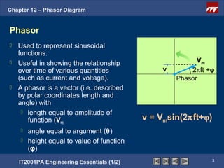
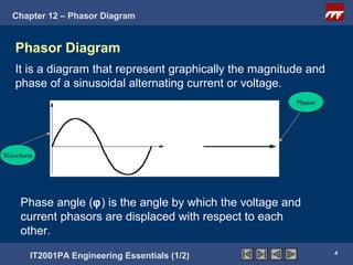
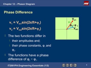
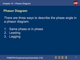
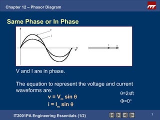
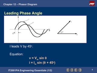
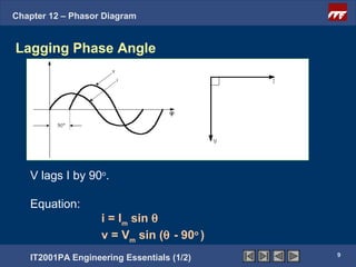

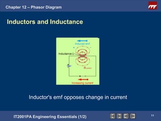
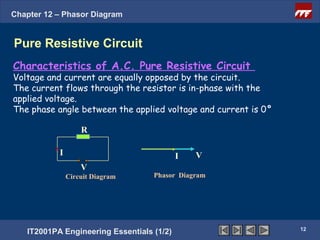
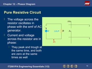


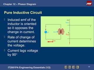


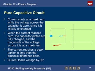
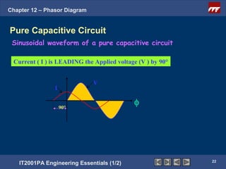
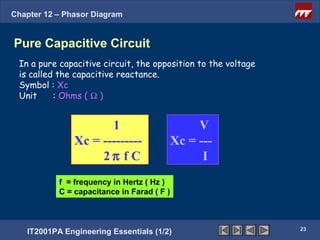


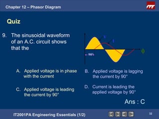
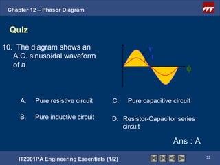


This document discusses phasor diagrams and their use in analyzing AC circuits. It begins by defining phasors and explaining that phasor diagrams represent the magnitude and phase of sinusoidal voltages and currents. The document then examines phasor diagrams for pure resistive, inductive, and capacitive circuits. In a pure resistive circuit, the current and voltage are in phase. In a pure inductive circuit, the current lags the voltage by 90 degrees. In a pure capacitive circuit, the current leads the voltage by 90 degrees. Characteristics of each type of circuit are provided along with examples of phasor diagrams.


![AC_CIRCUITS[1].pptx](https://cdn.slidesharecdn.com/ss_thumbnails/accircuits1-230813170350-dc7f310b-thumbnail.jpg?width=640&height=640&fit=bounds)