The document defines key concepts in AC circuits including:
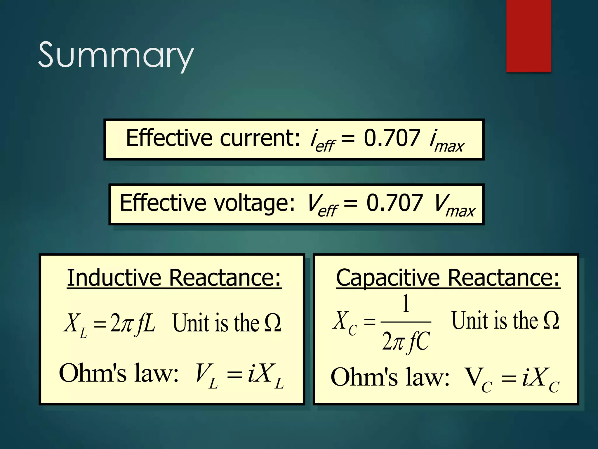
- Effective current and voltage as 0.707 times peak values
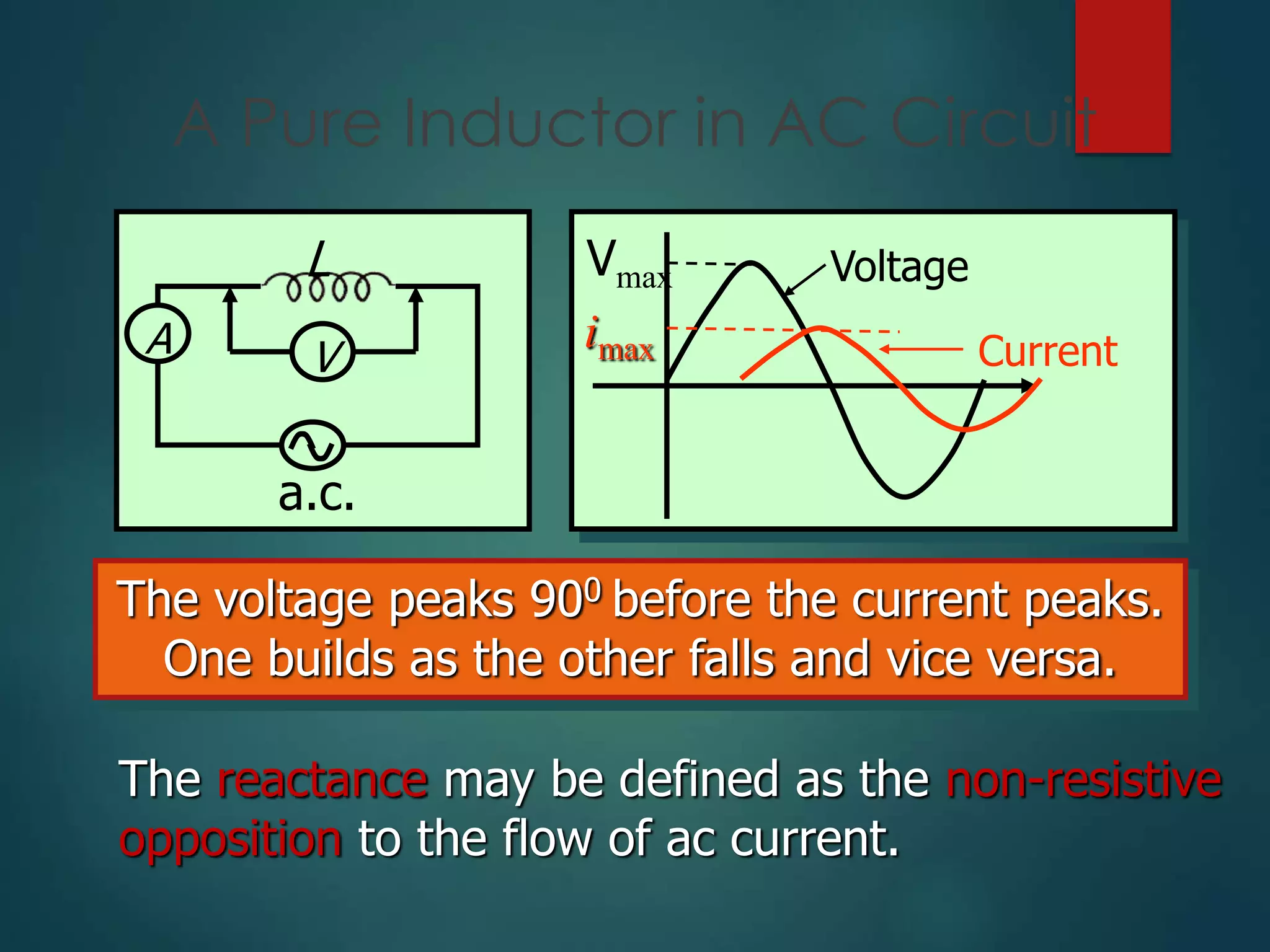
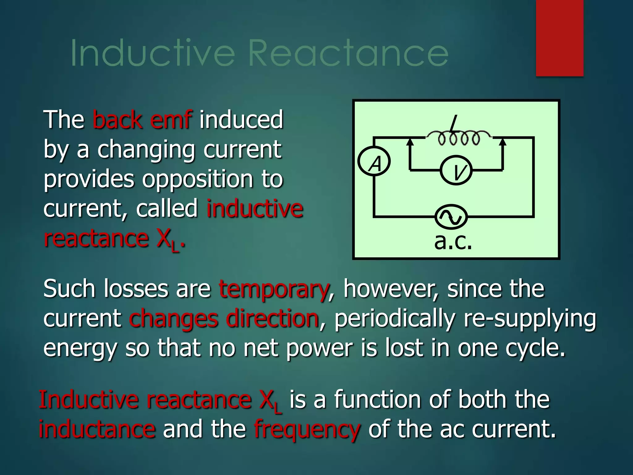
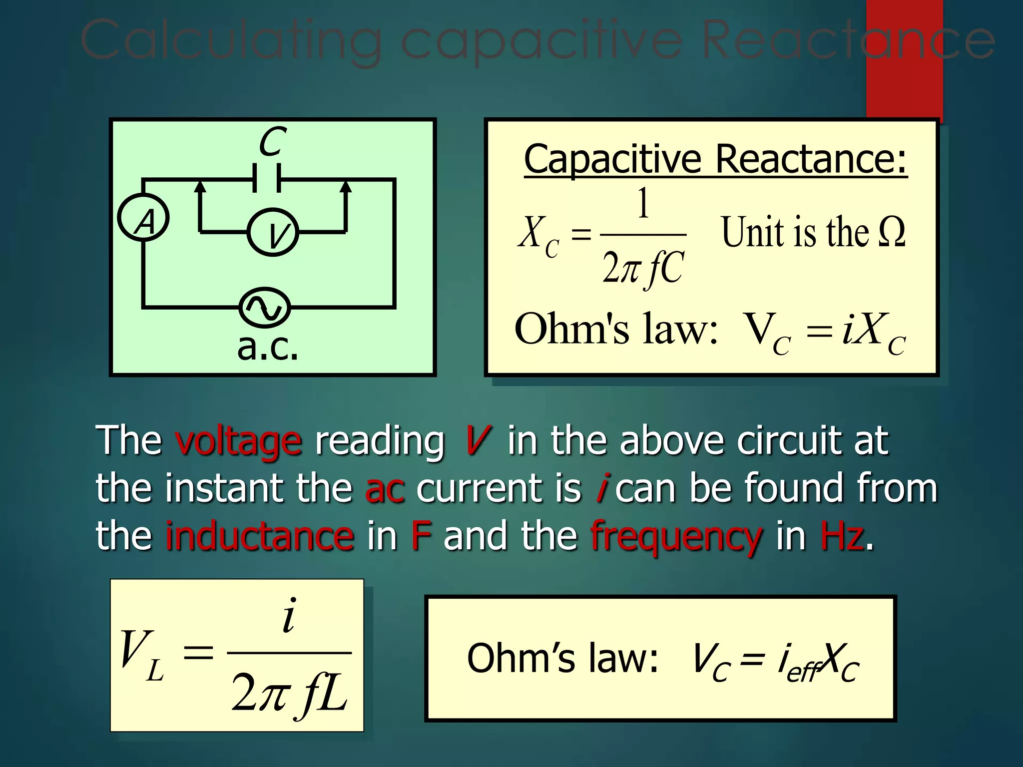
- Inductive and capacitive reactance defined as functions of inductance/capacitance and frequency
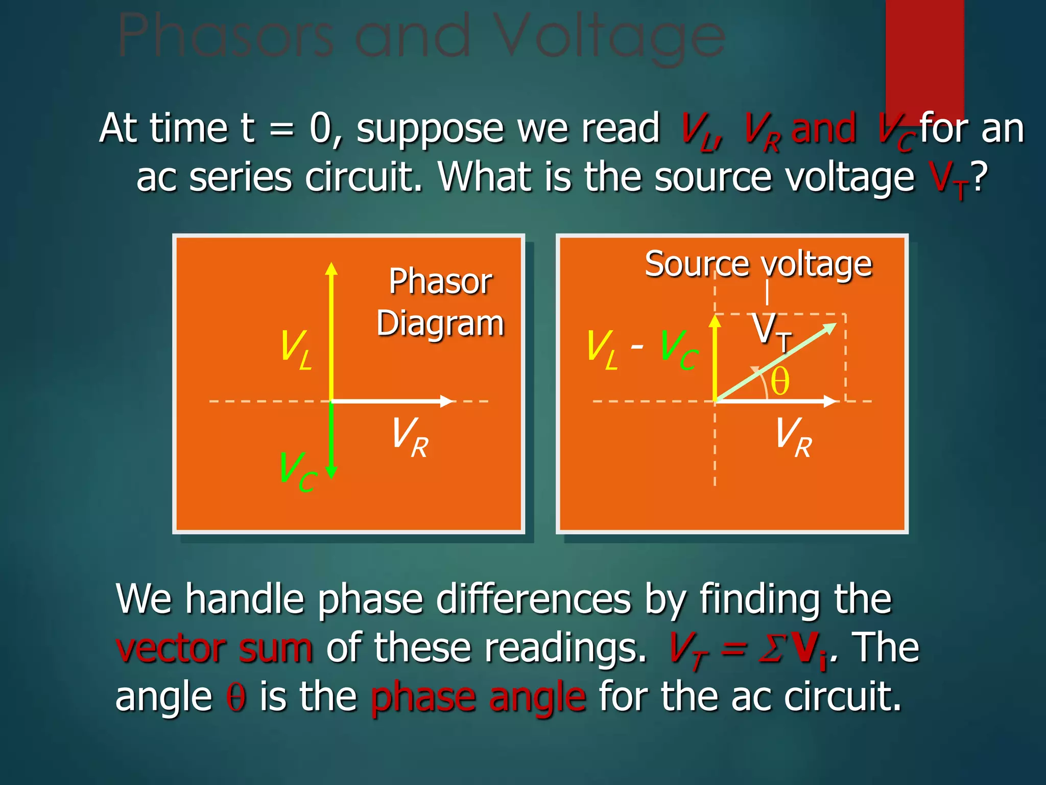
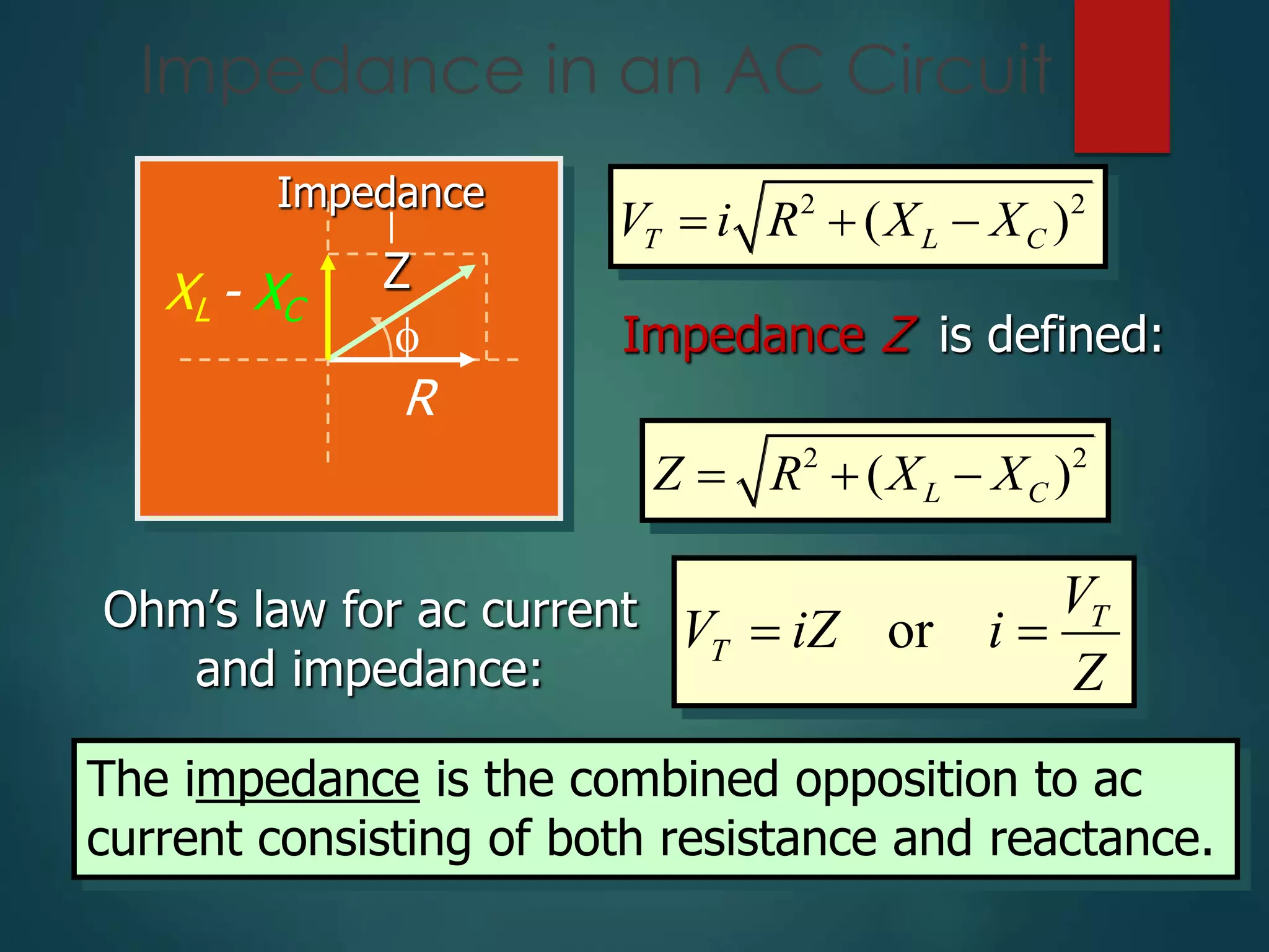
- Impedance in an AC circuit calculated as the vector sum of resistance and reactance
- Resonant frequency occurs when inductive and capacitive reactance values are equal
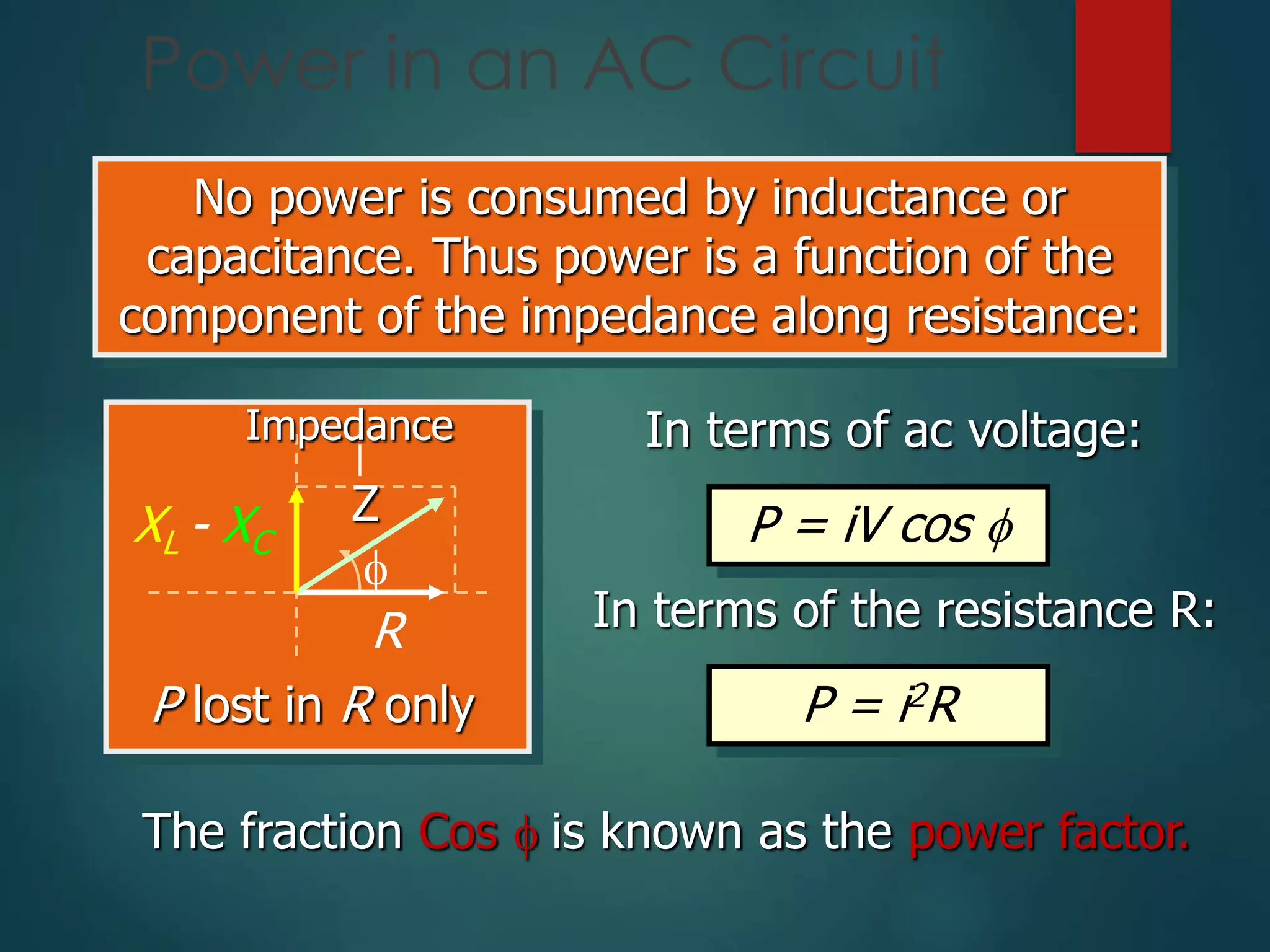
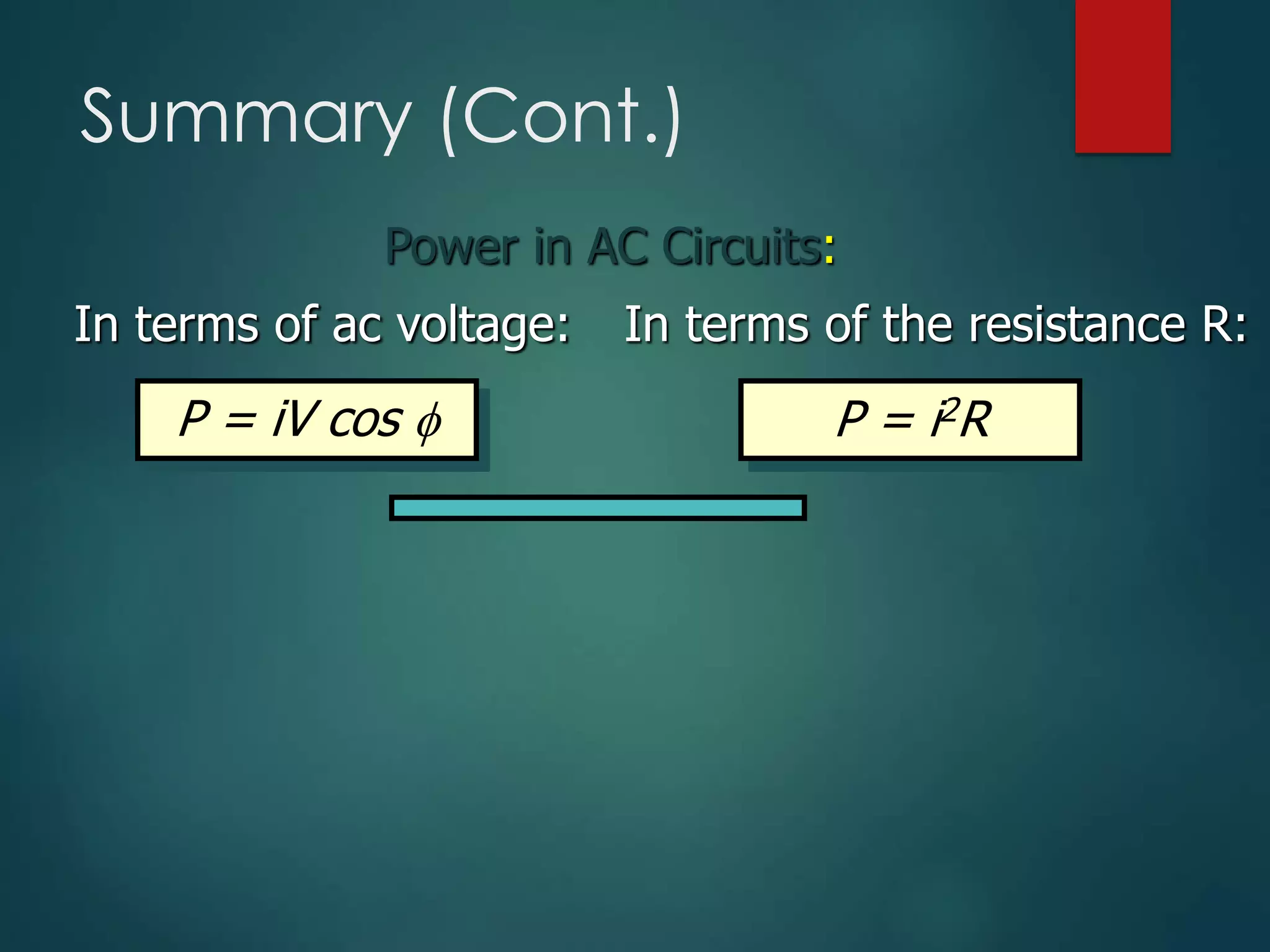
- Power in an AC circuit depends on the resistance component and is calculated using current, voltage, and power factor