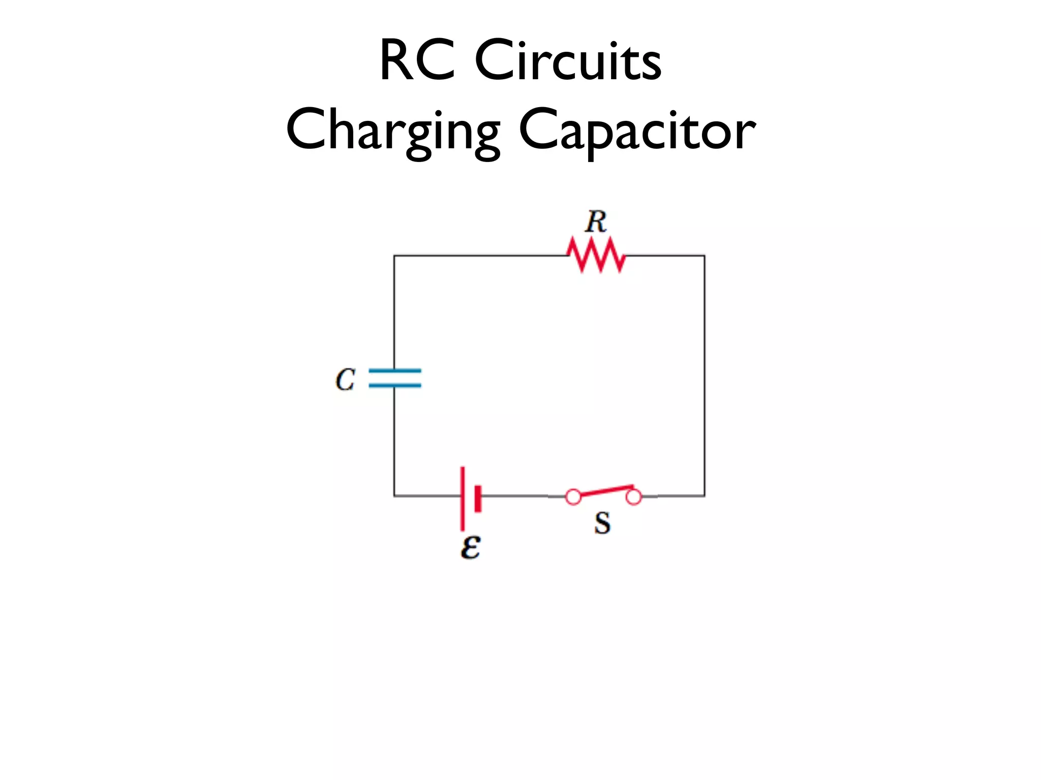
RC Circuits
Charging Capacitor
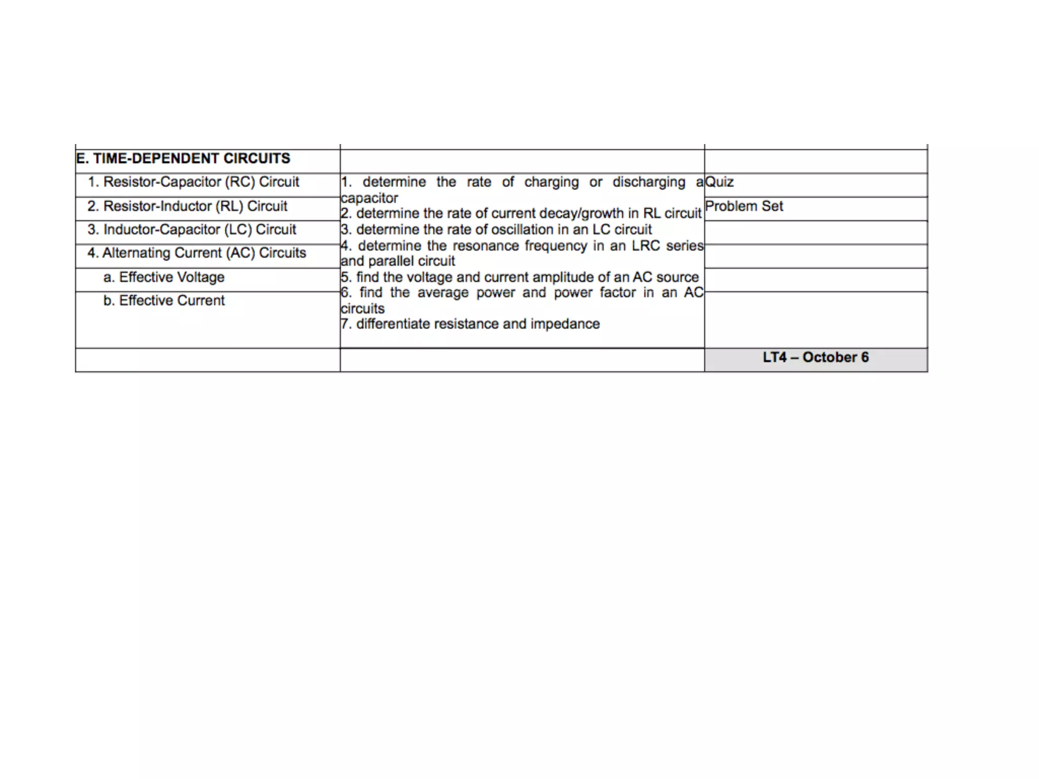
The capacitor is neutral
No current flows through the circuit
3.
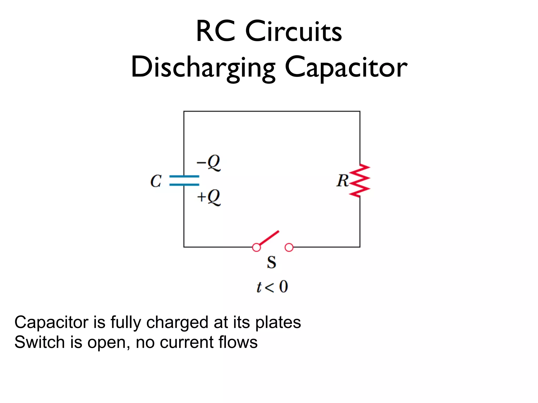
RC Circuits
Charging Capacitor
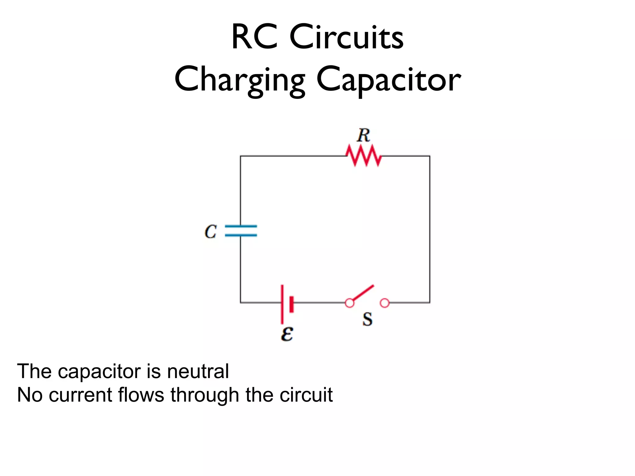
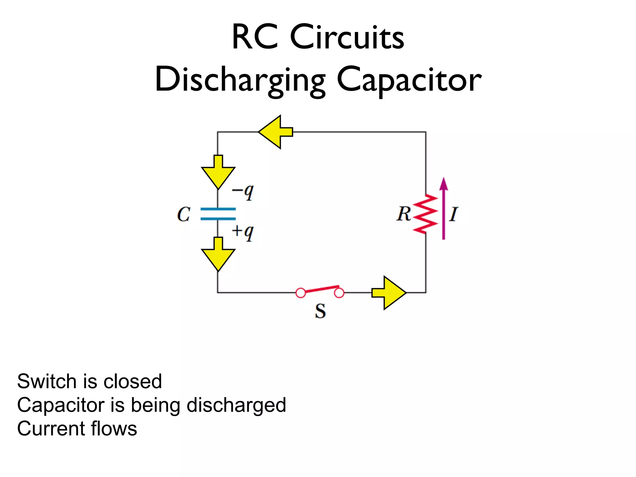
The switch is closed
Maximum current flows
4.
RC Circuits
Charging Capacitor
+q
-q
+q
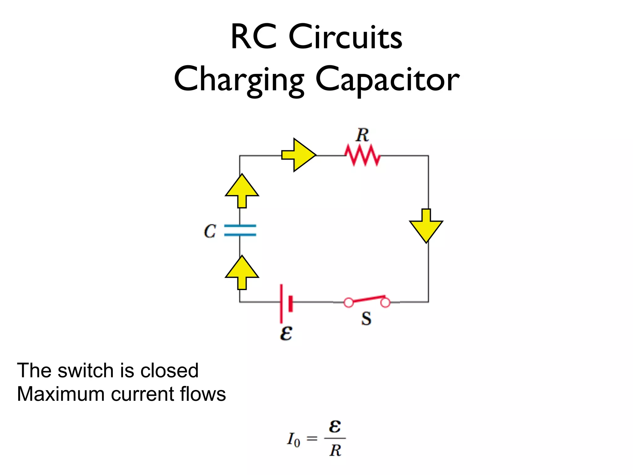
+q goes to lower part of capacitor
+q is repelled from upper part of capacitor leaving a -q charge
As the lower plate increases in + charge, current decreases due to
repulsion
5.
RC Circuits
Charging Capacitor
+q
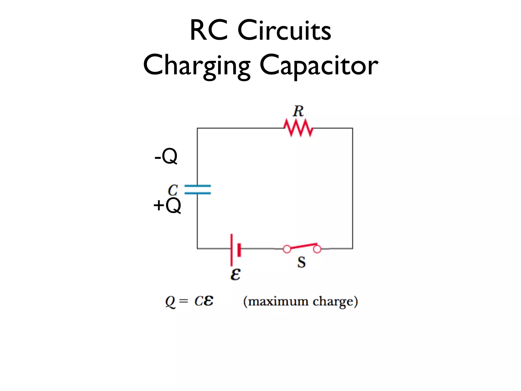
-Q
+Q
+q
+q
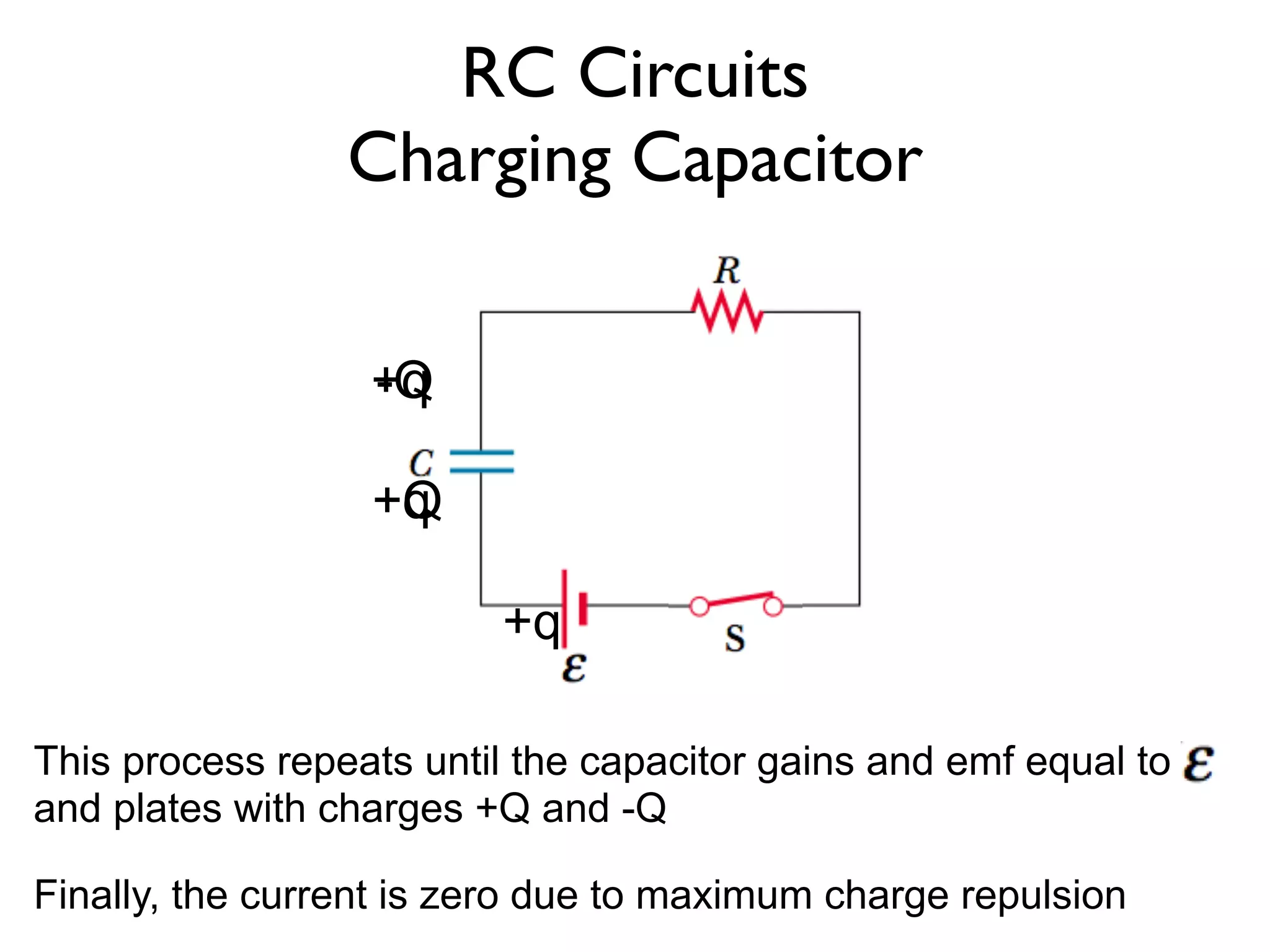
This process repeats until the capacitor gains and emf equal to
and plates with charges +Q and -Q
Finally, the current is zero due to maximum charge repulsion
RC Circuits
Charging Capacitor
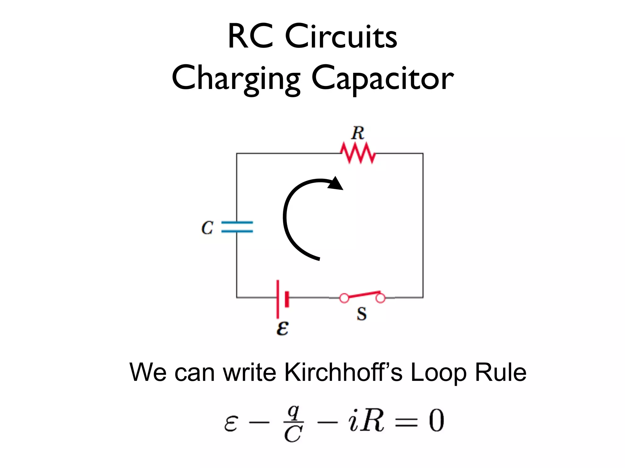
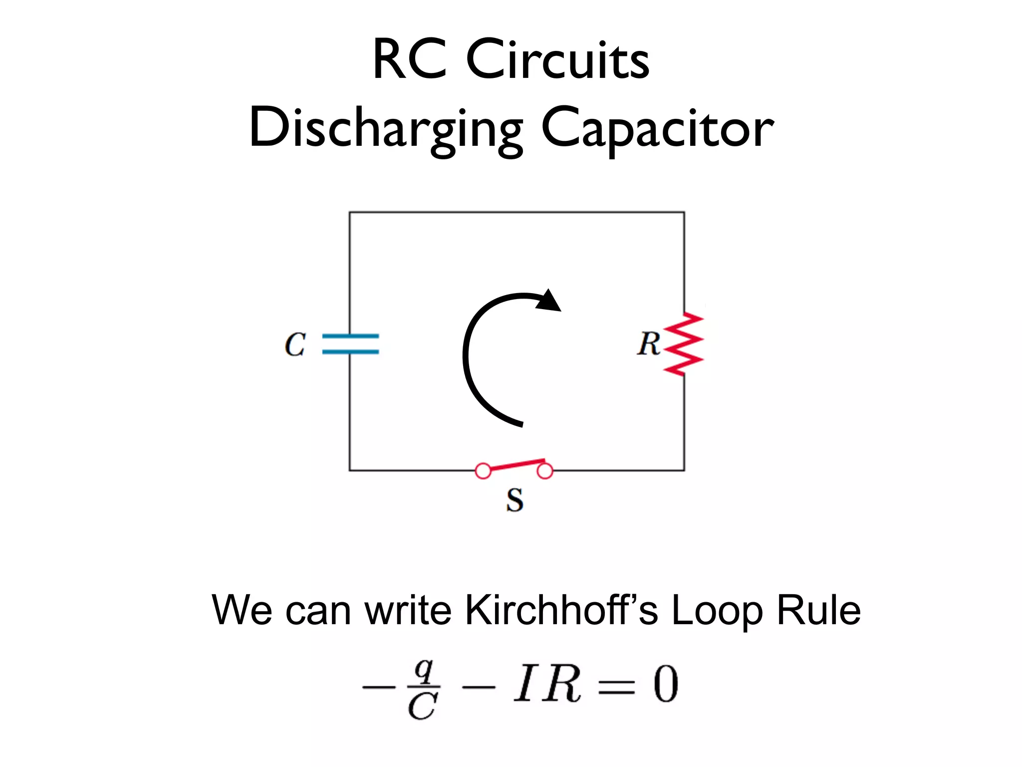
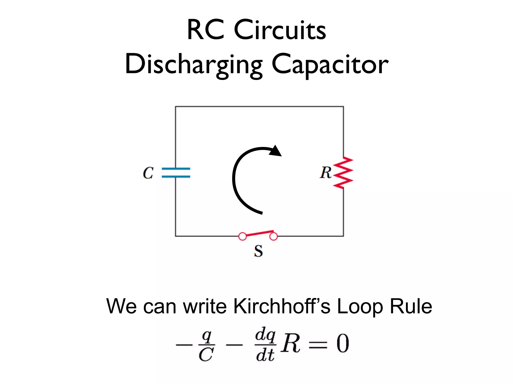
We can write Kirchhoff’s Loop Rule
8.
RC Circuits
Charging Capacitor
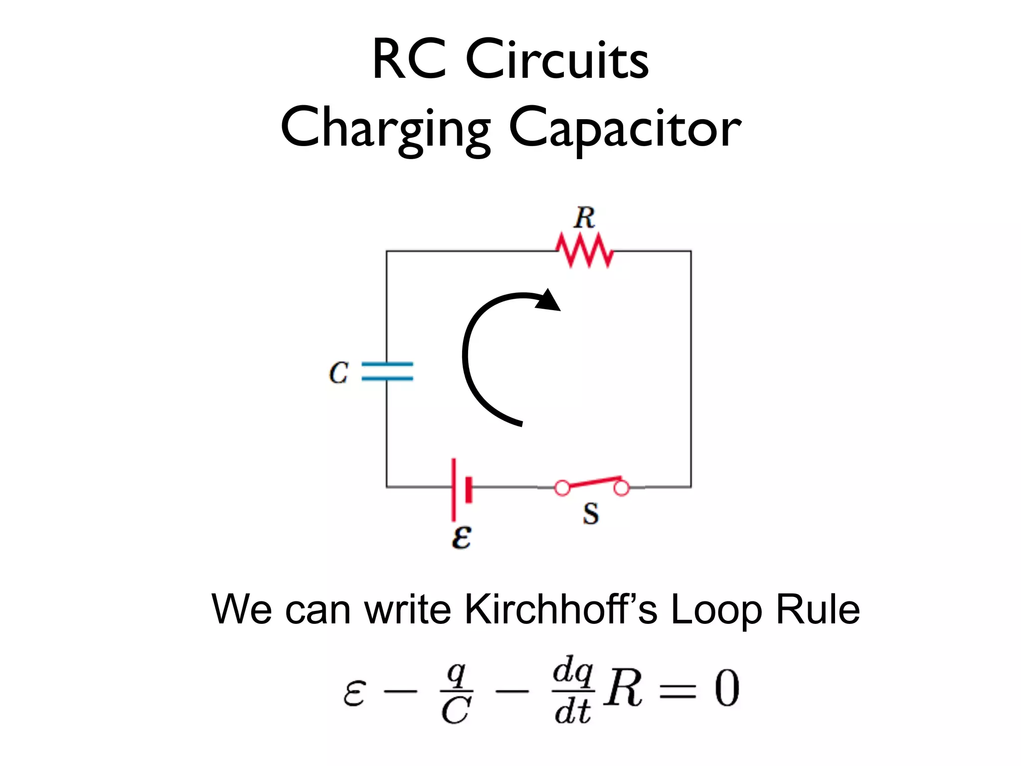
We can write Kirchhoff’s Loop Rule
9.
RC Circuits
ChargingCapacitor
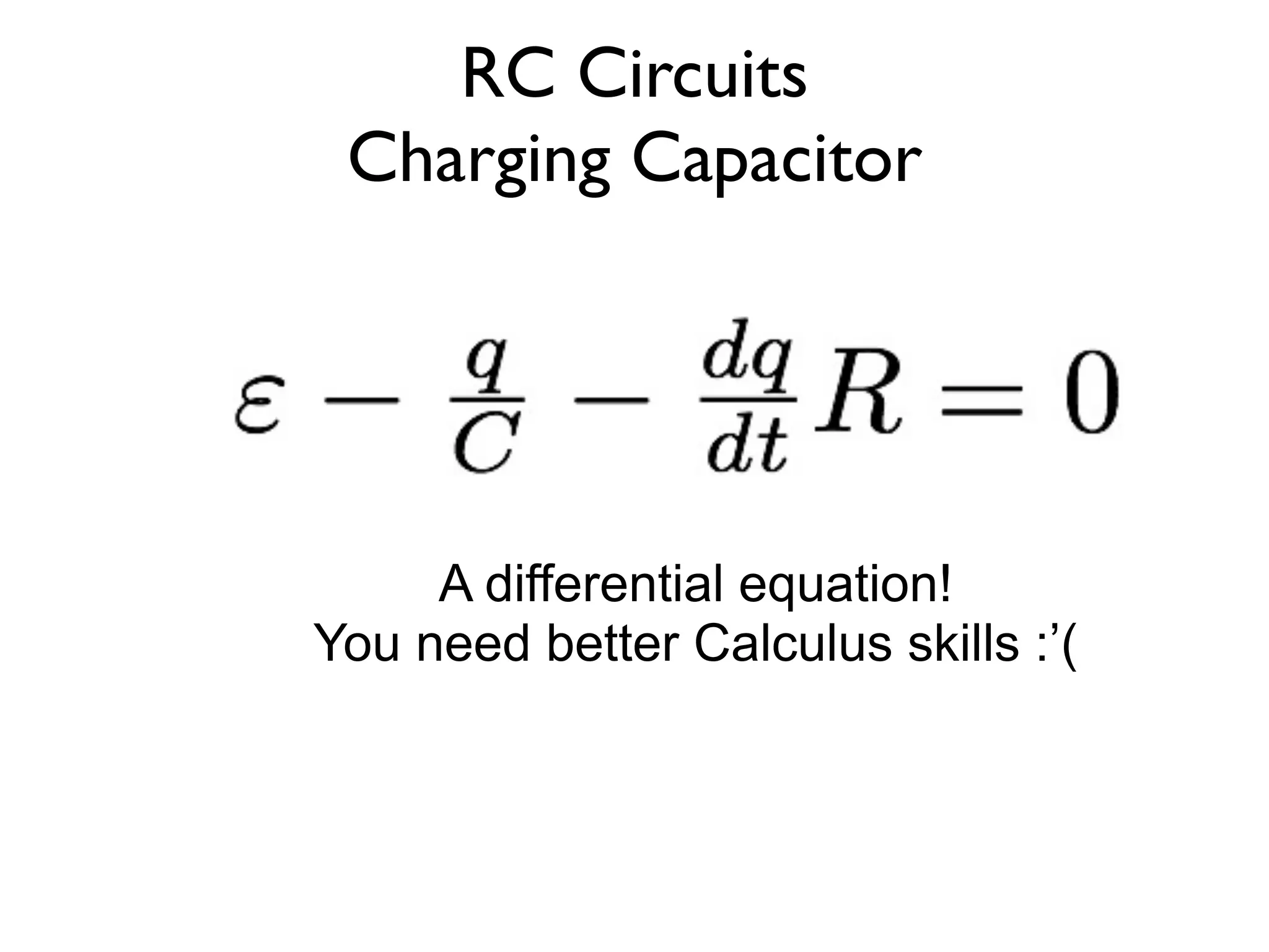
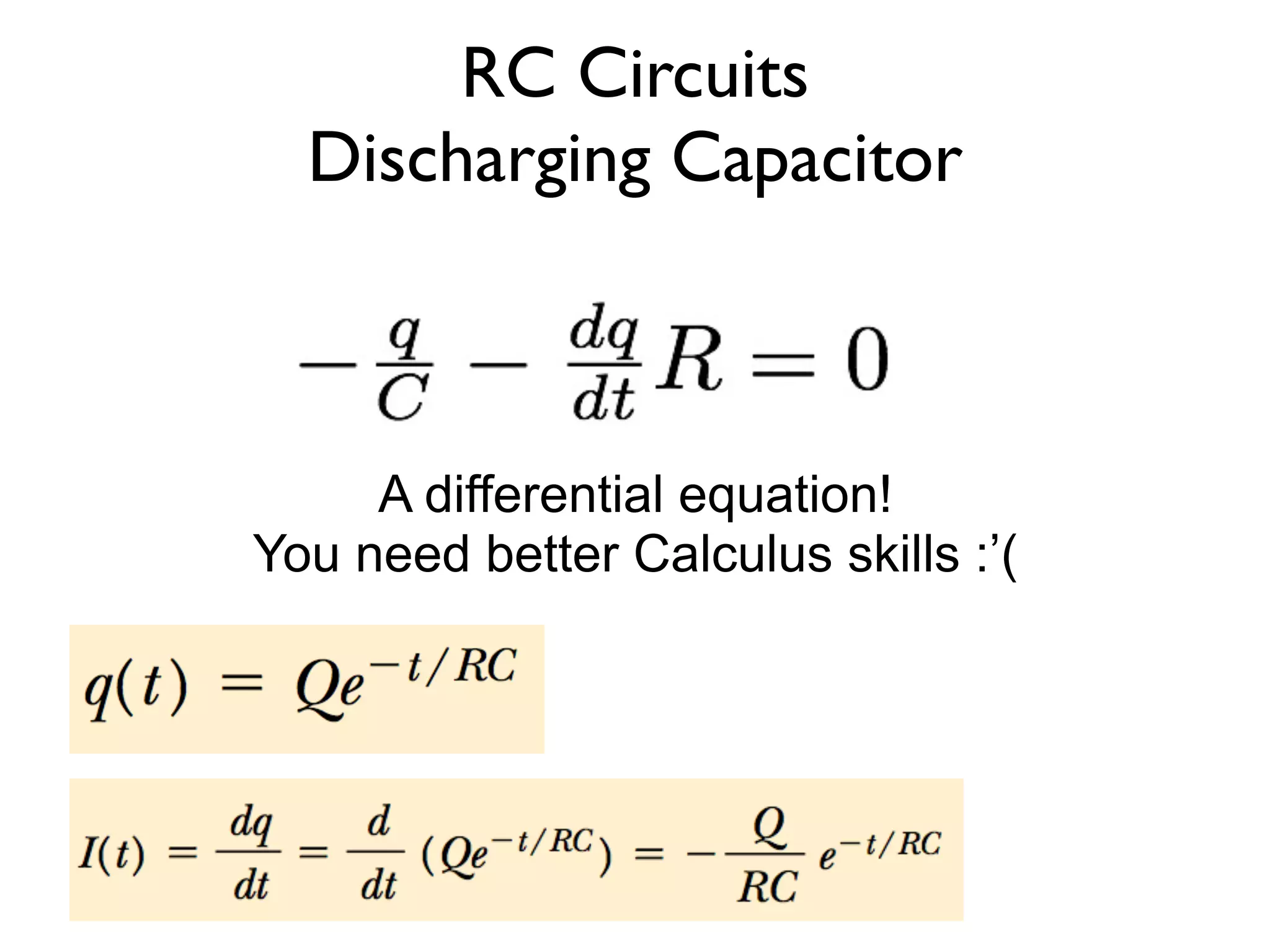
A differential equation!
You need better Calculus skills :’(
10.
RC Circuits
Charging Capacitor
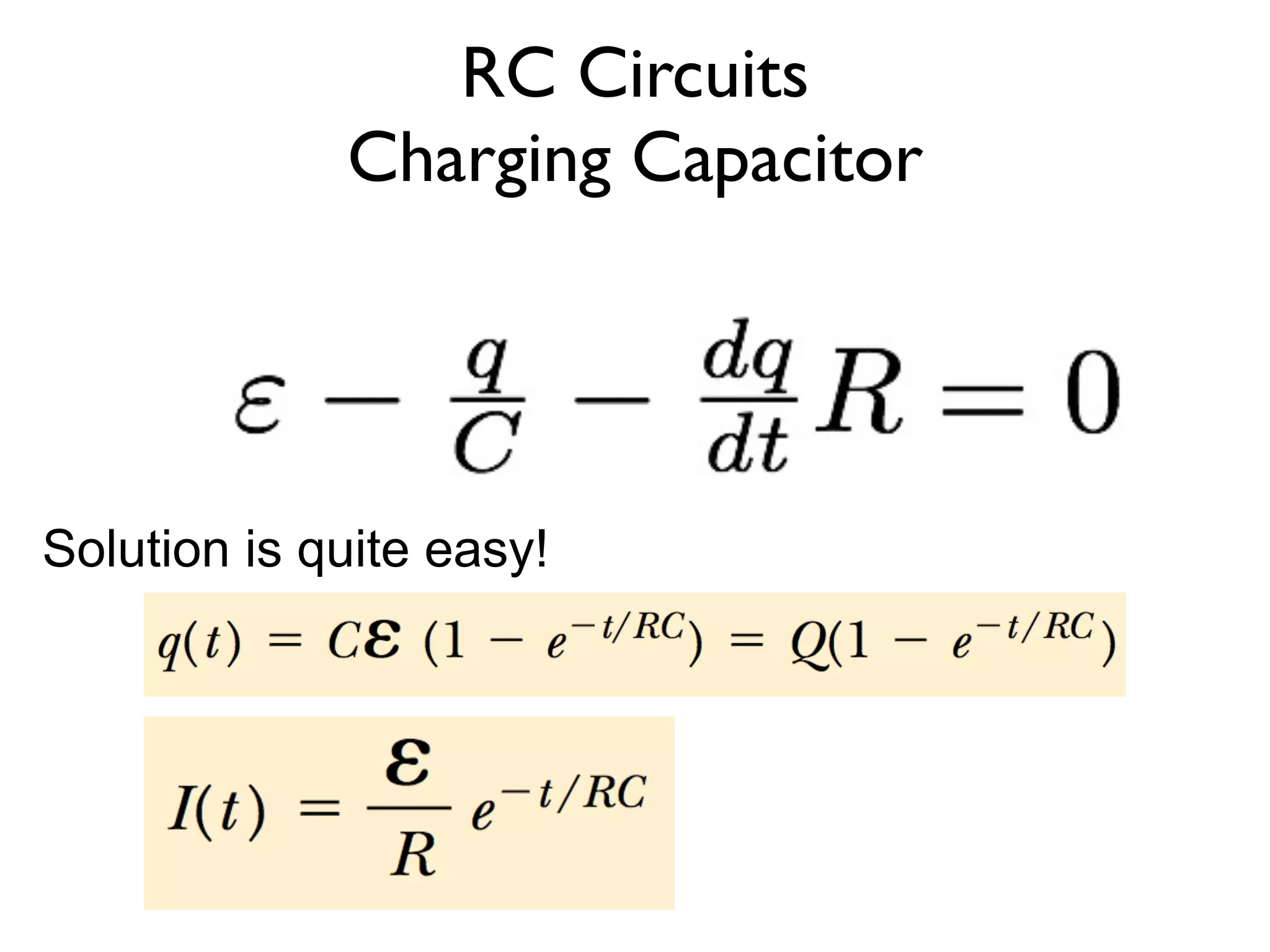
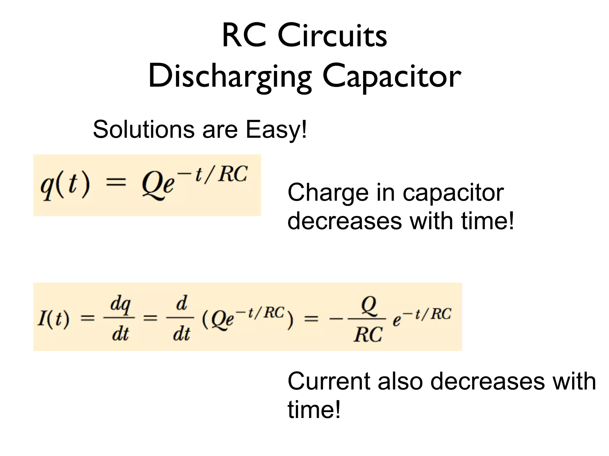
Solution is quite easy!
11.
RC Circuits
Charging Capacitor
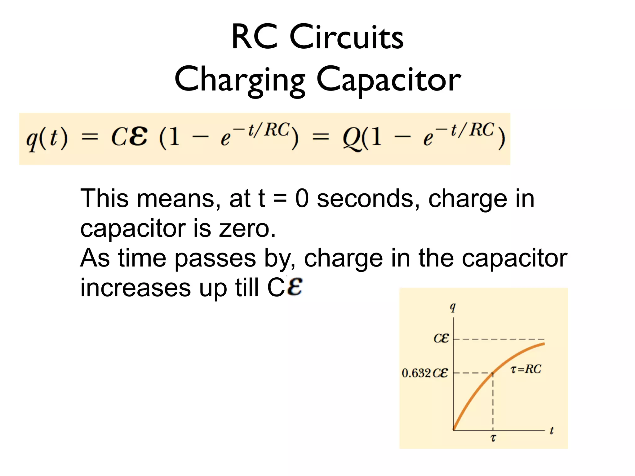
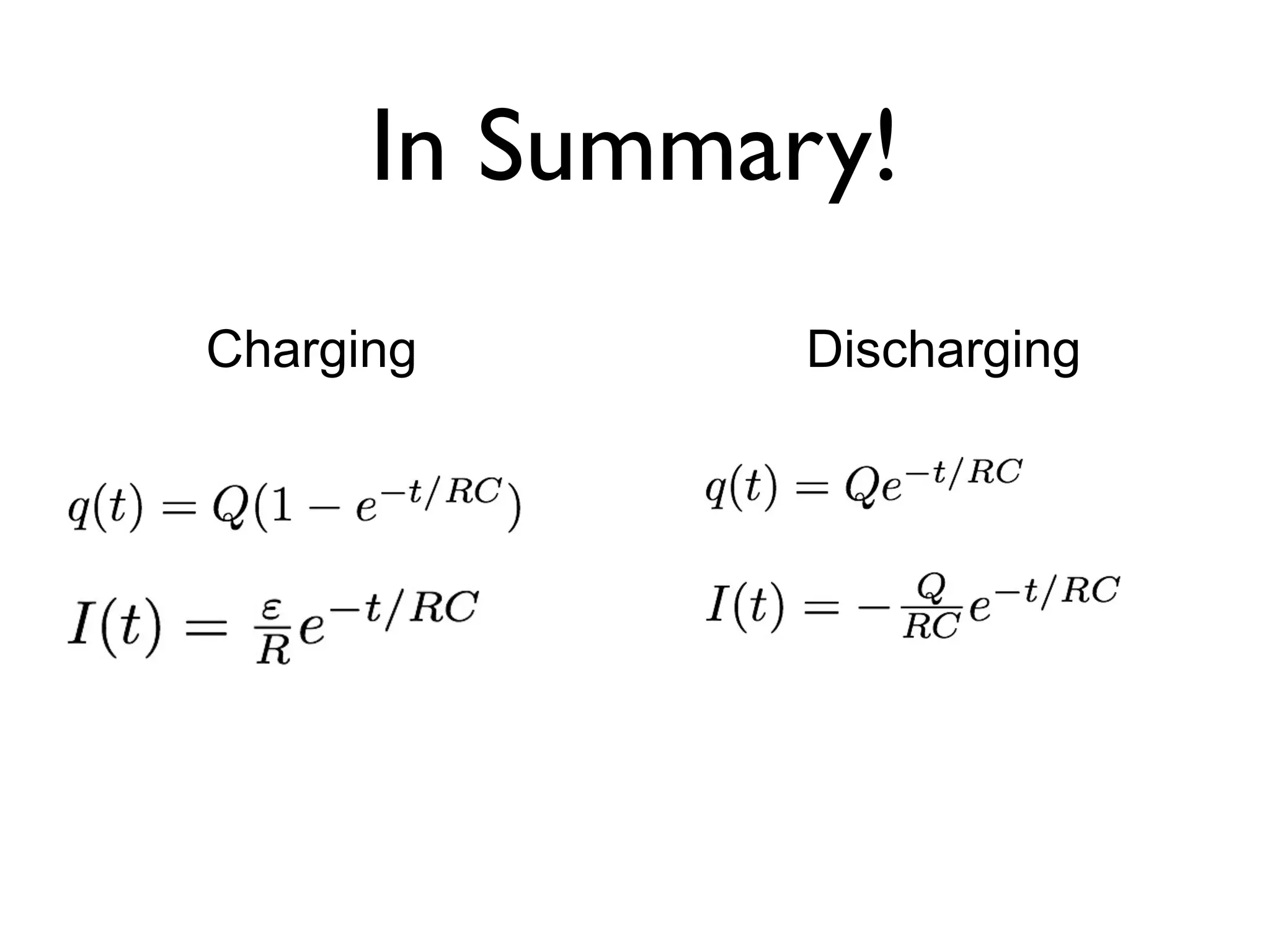
This means, at t = 0 seconds, charge in
capacitor is zero.
As time passes by, charge in the capacitor
increases up till C
12.
RC Circuits
Charging Capacitor
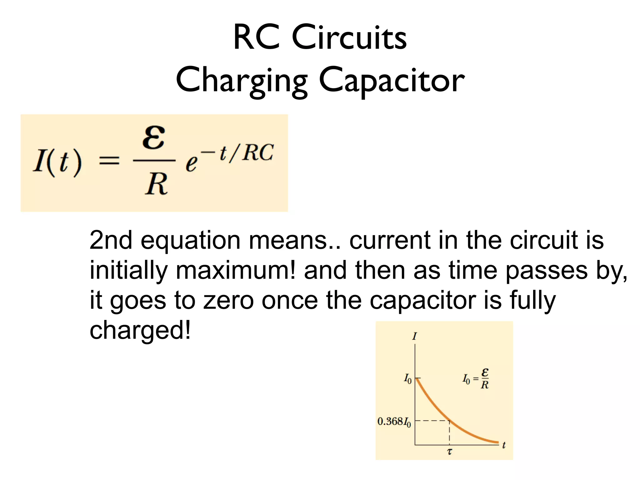
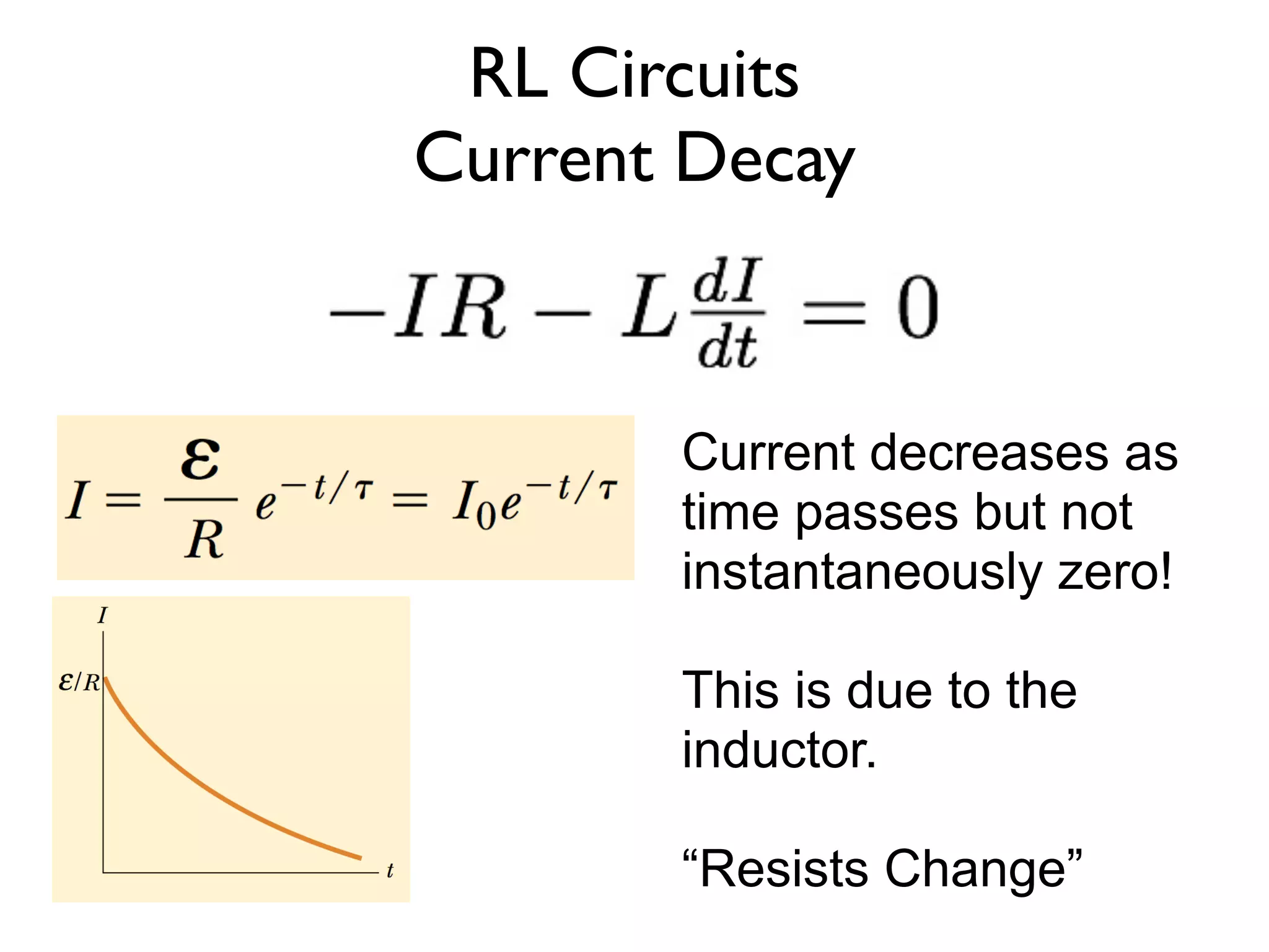
2nd equation means.. current in the circuit is
initially maximum! and then as time passes by,
it goes to zero once the capacitor is fully
charged!
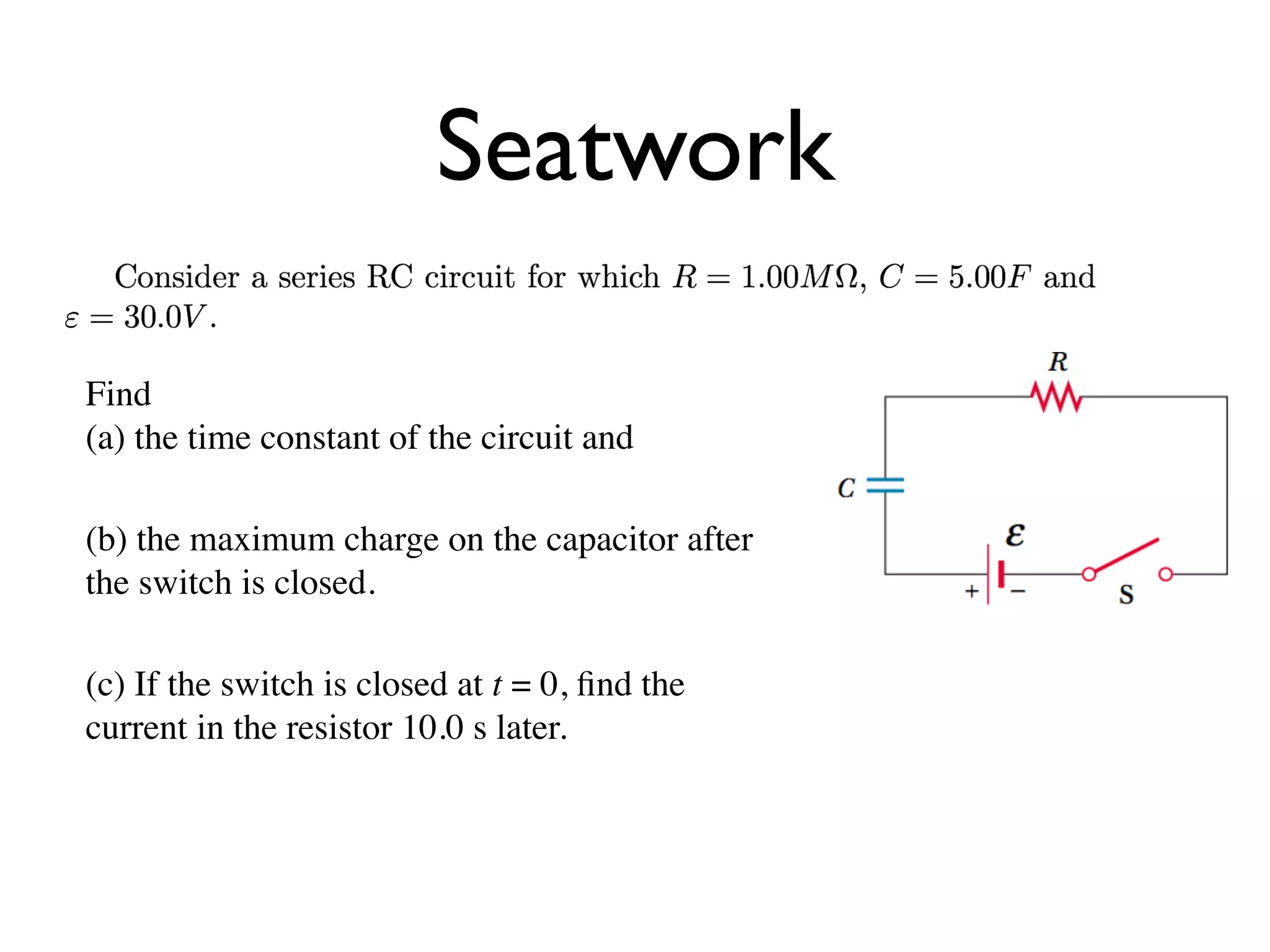
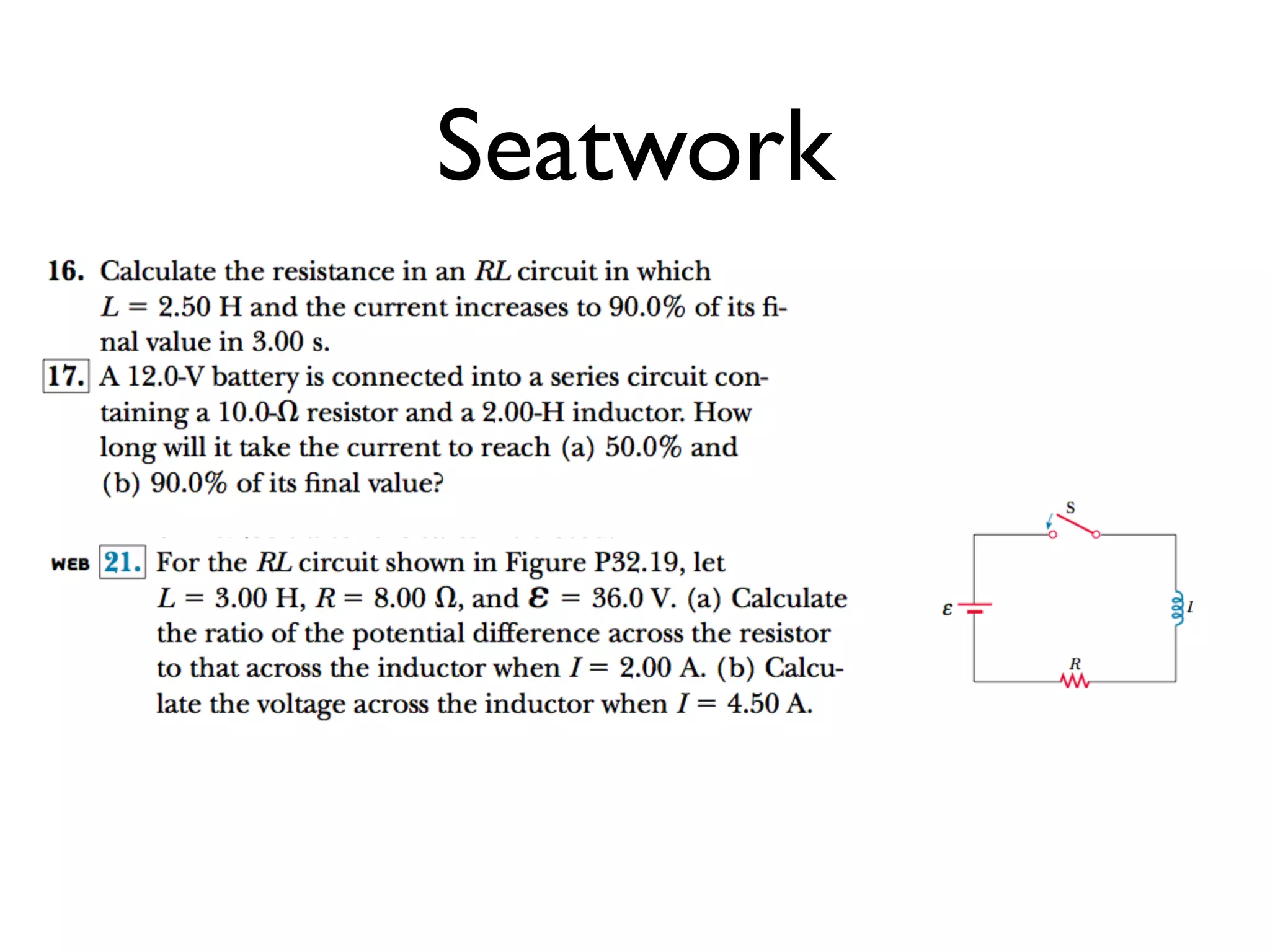
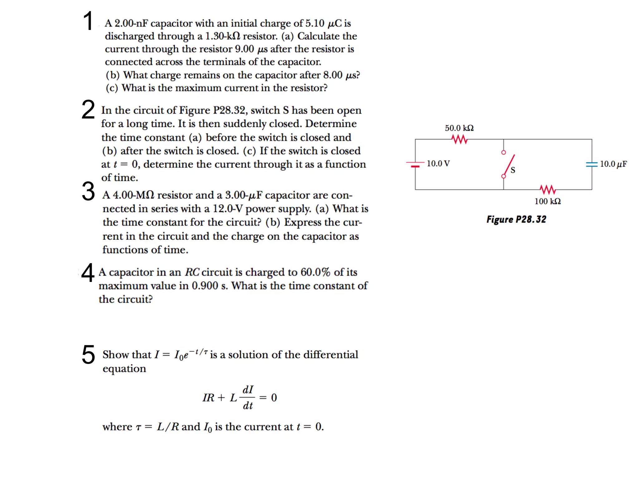
Seatwork
Find
(a) the timeconstant of the circuit and
(b) the maximum charge on the capacitor after
the switch is closed.
(c) If the switch is closed at t = 0, find the
current in the resistor 10.0 s later.
23.
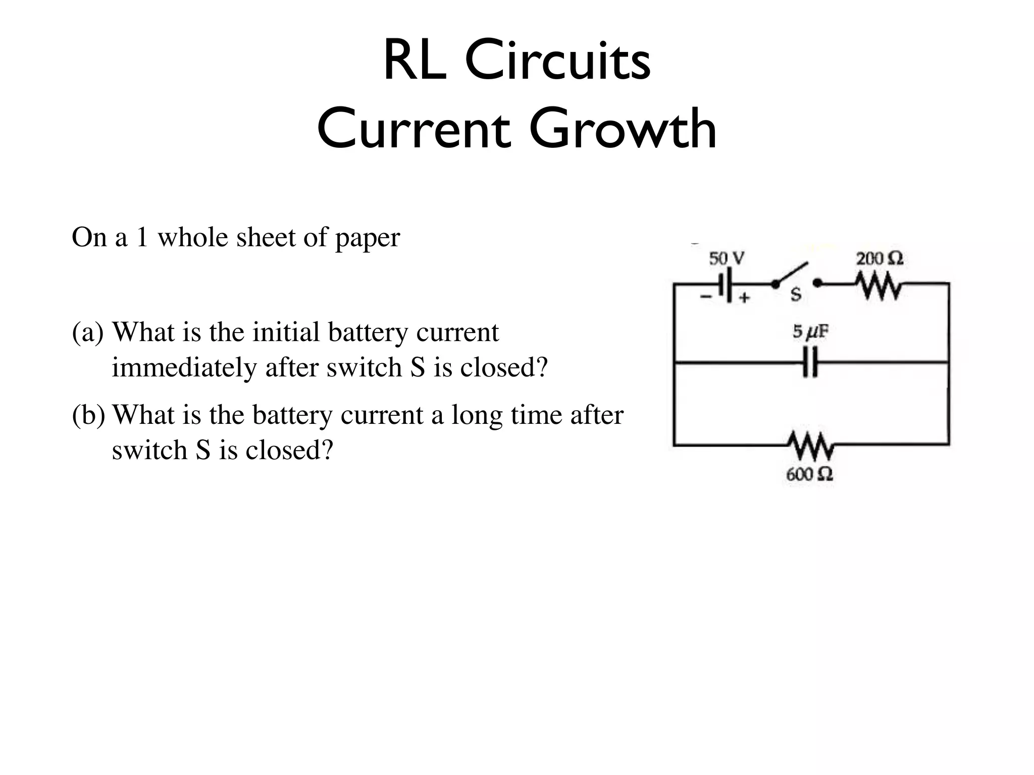
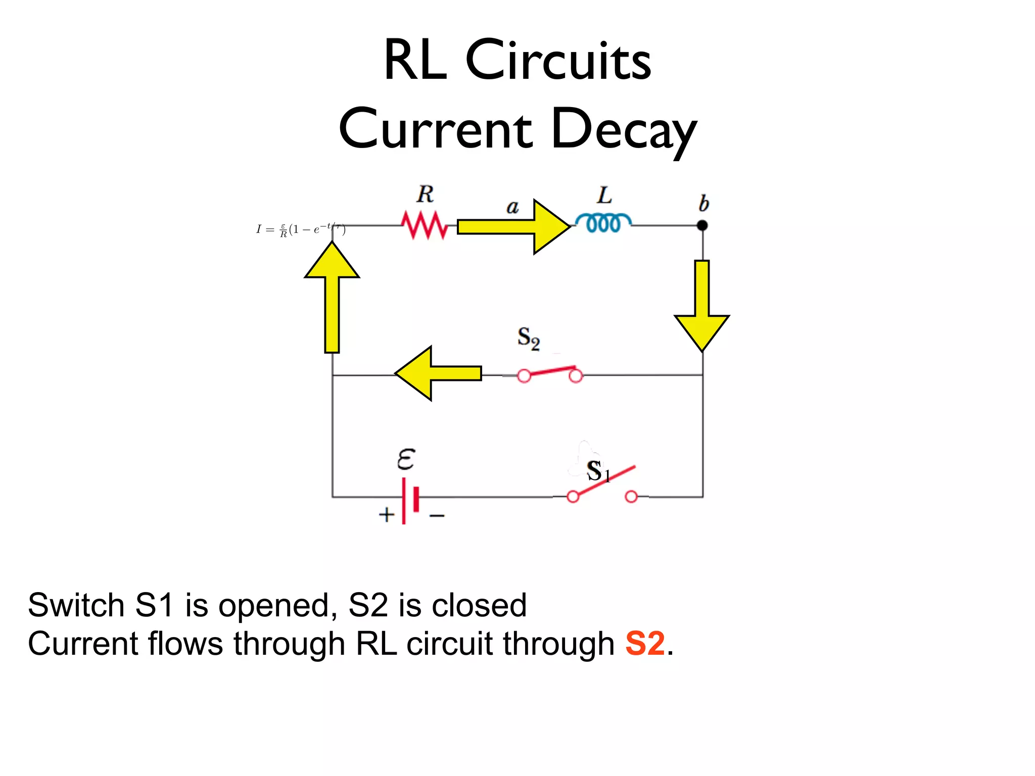
RL Circuits
Current Growth
On a 1 whole sheet of paper
(a) What is the initial battery current
immediately after switch S is closed?
(b) What is the battery current a long time after
switch S is closed?
24.
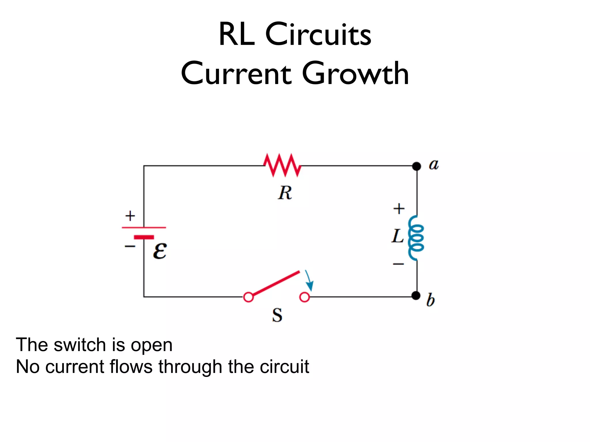
RL Circuits
Current Growth
The switch is open
No current flows through the circuit
25.
RL Circuits
Current Growth
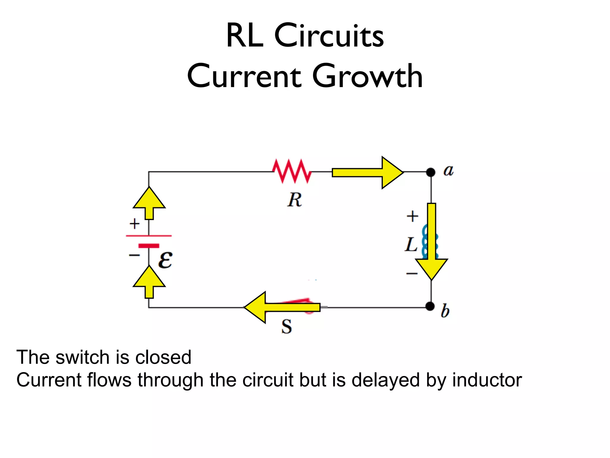
The switch is closed
Current flows through the circuit but is delayed by inductor
26.
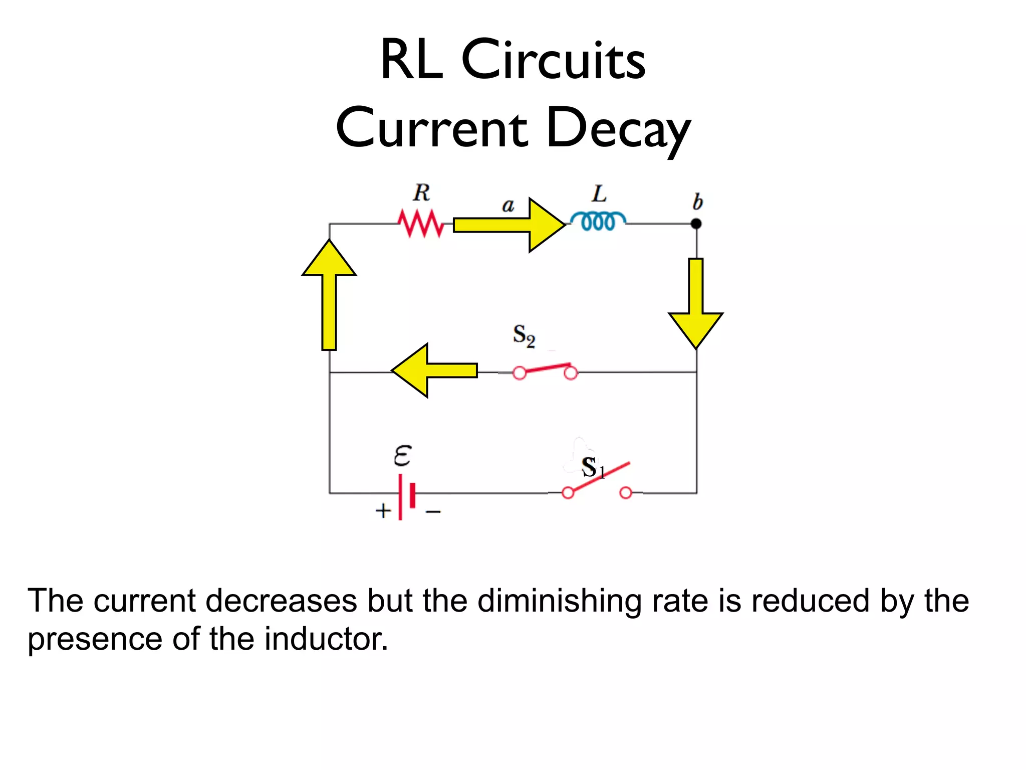
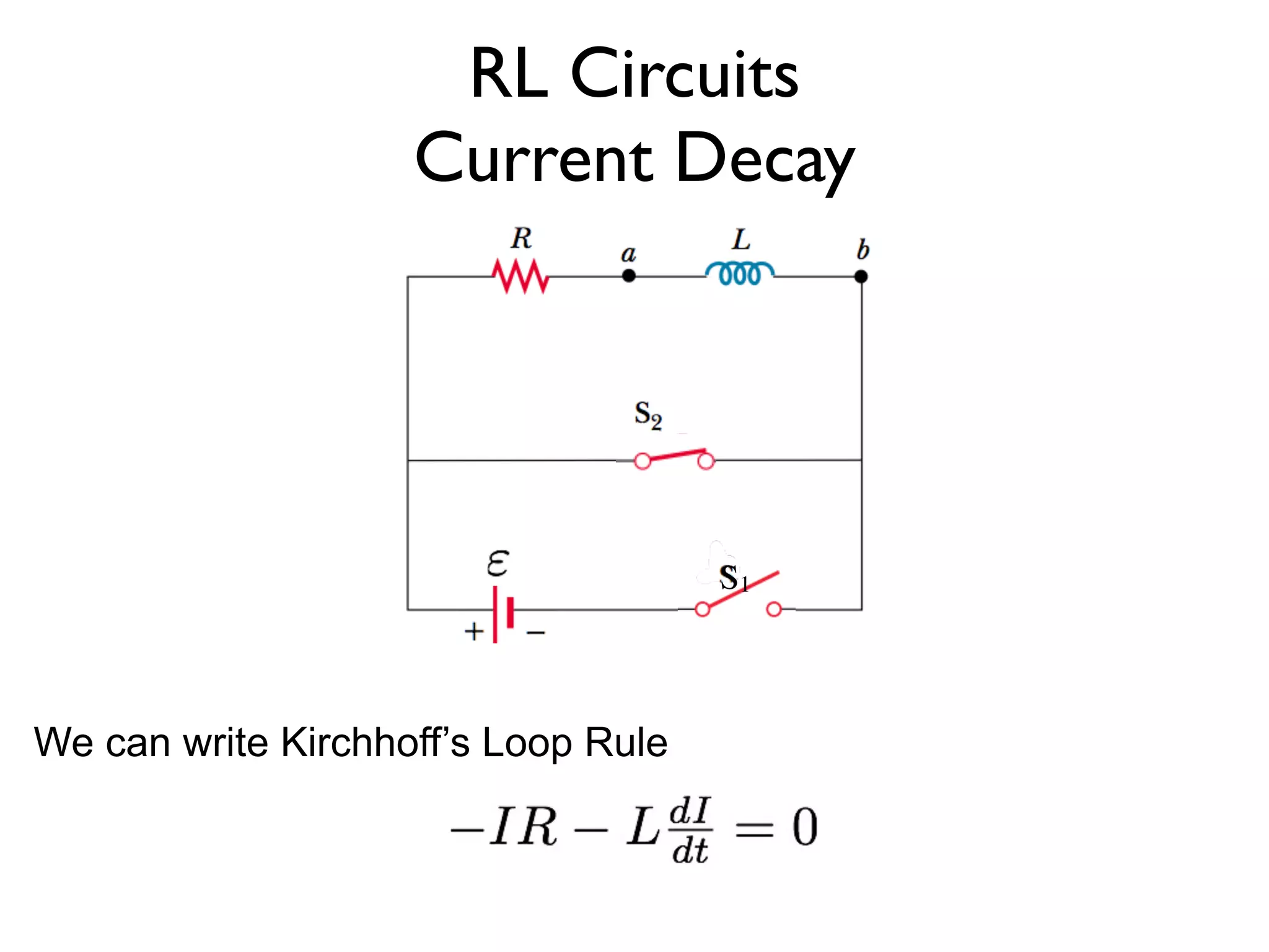
RL Circuits
Current Growth
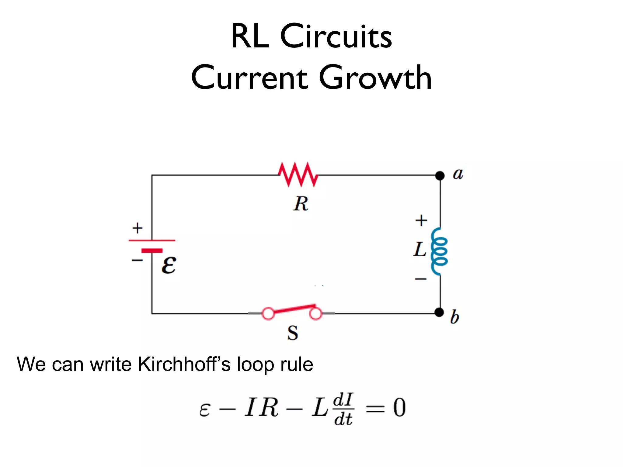
We can write Kirchhoff’s loop rule
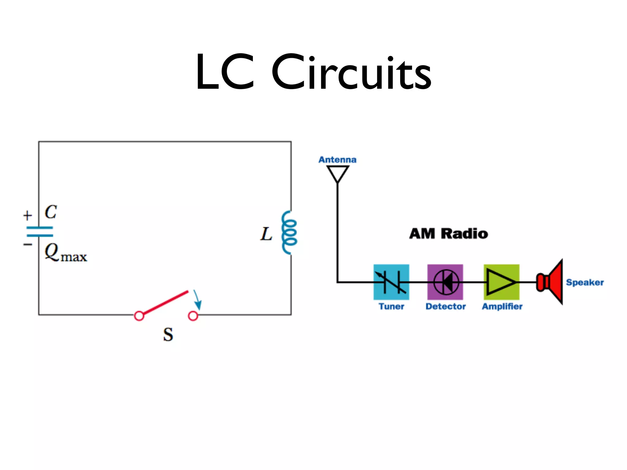
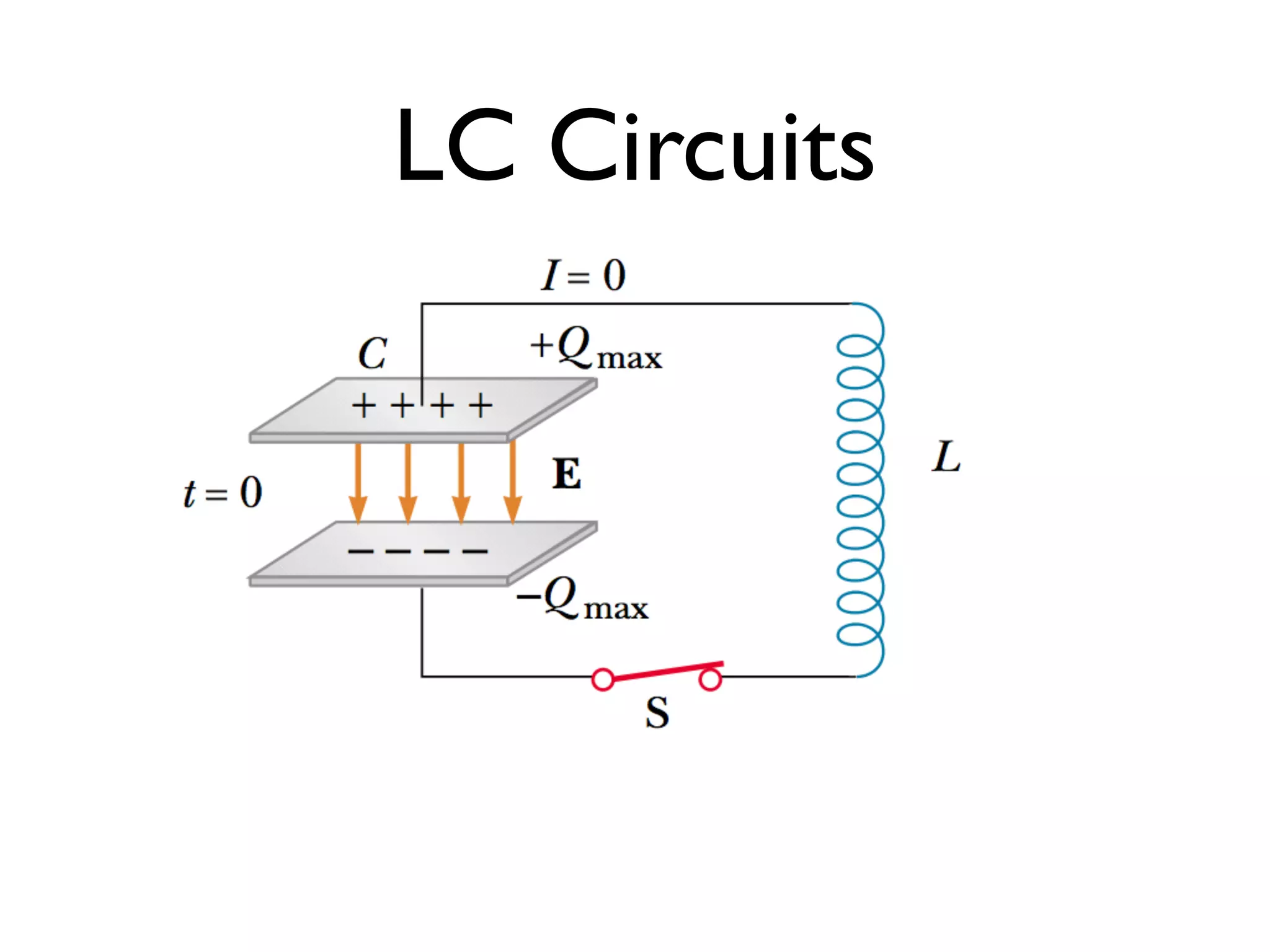
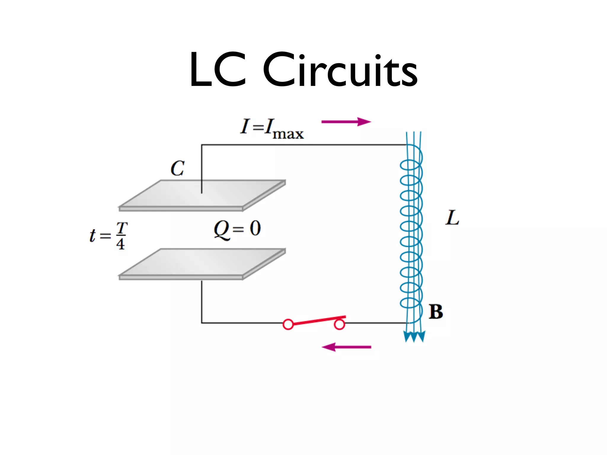
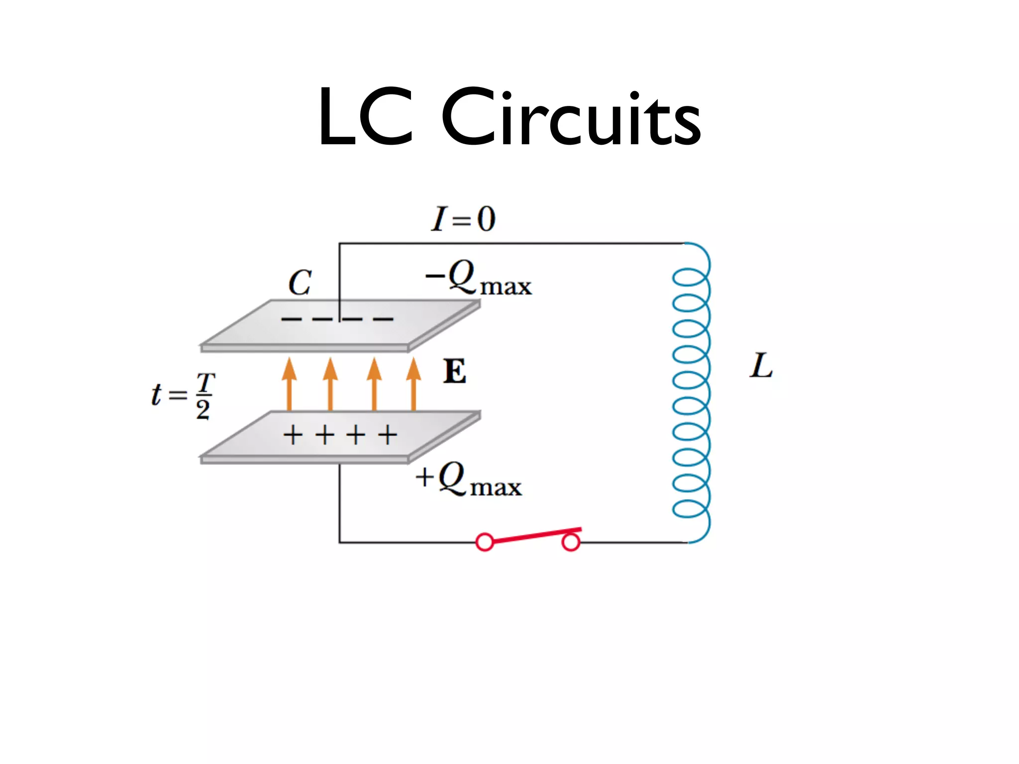
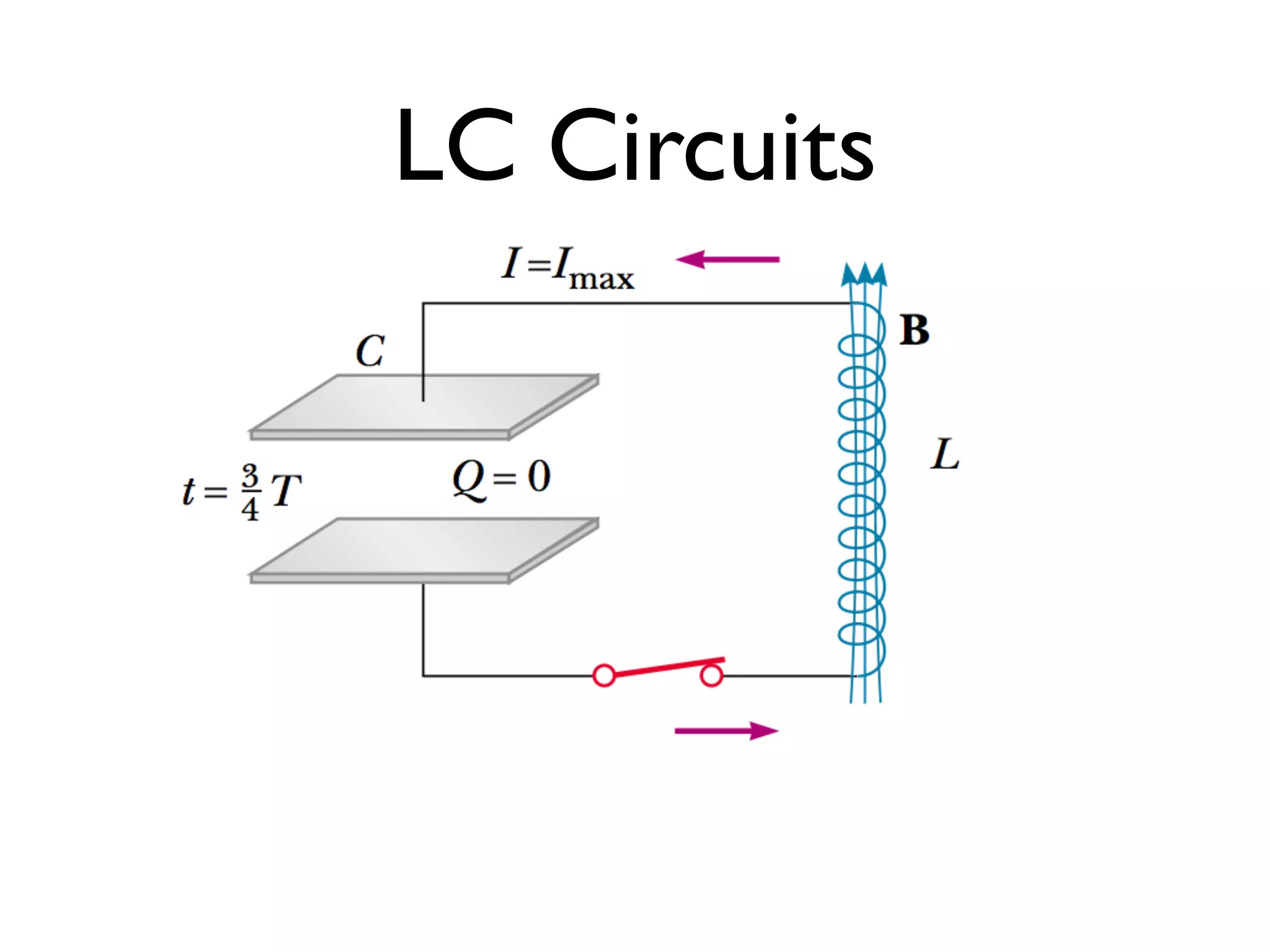
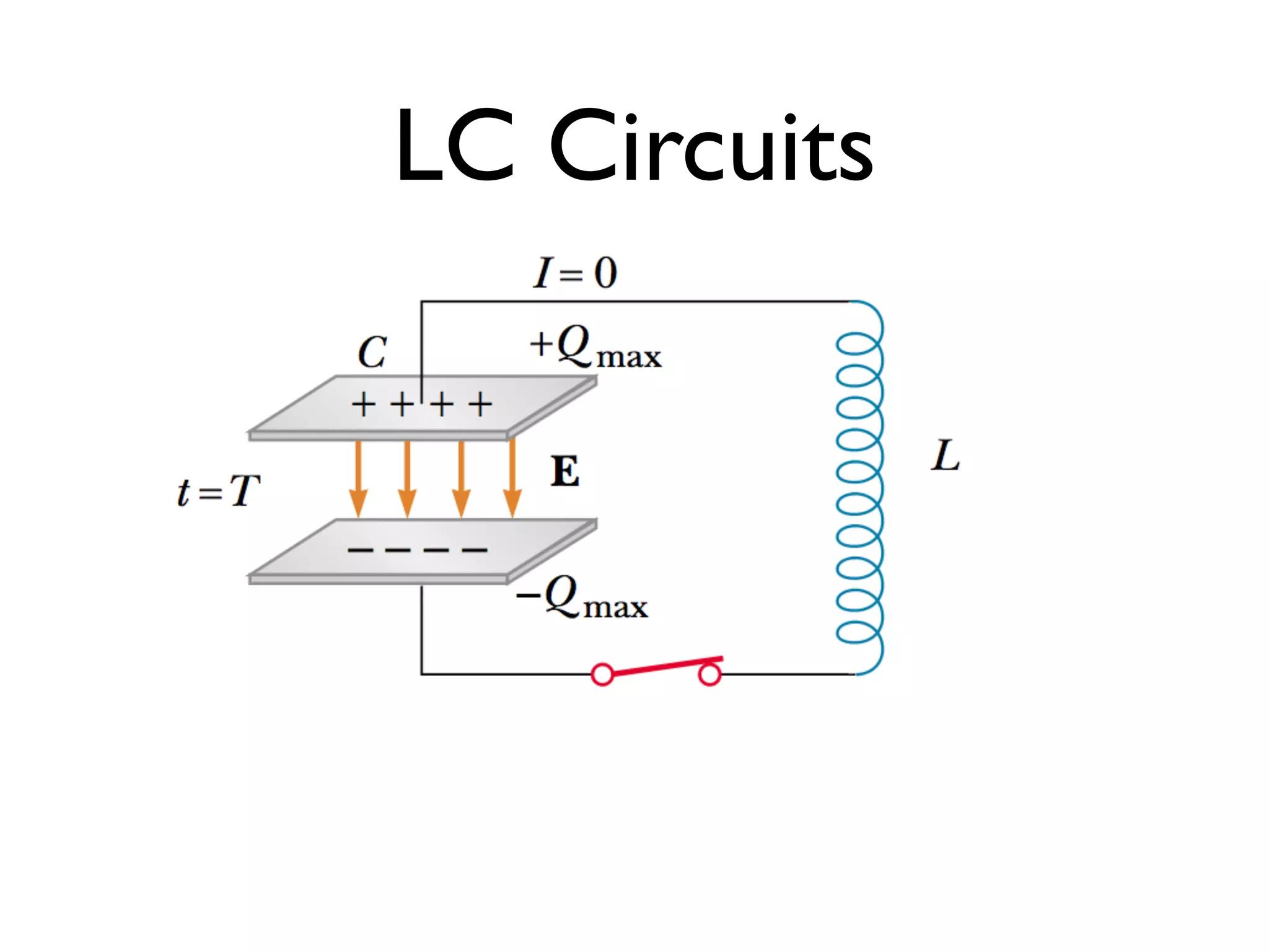
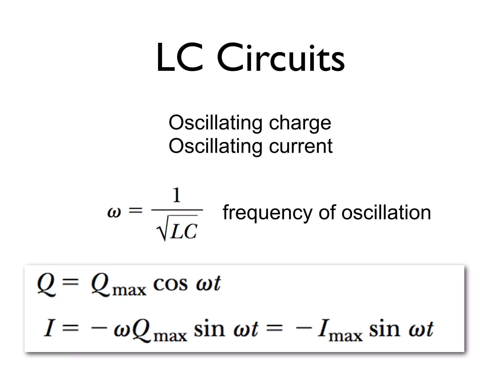
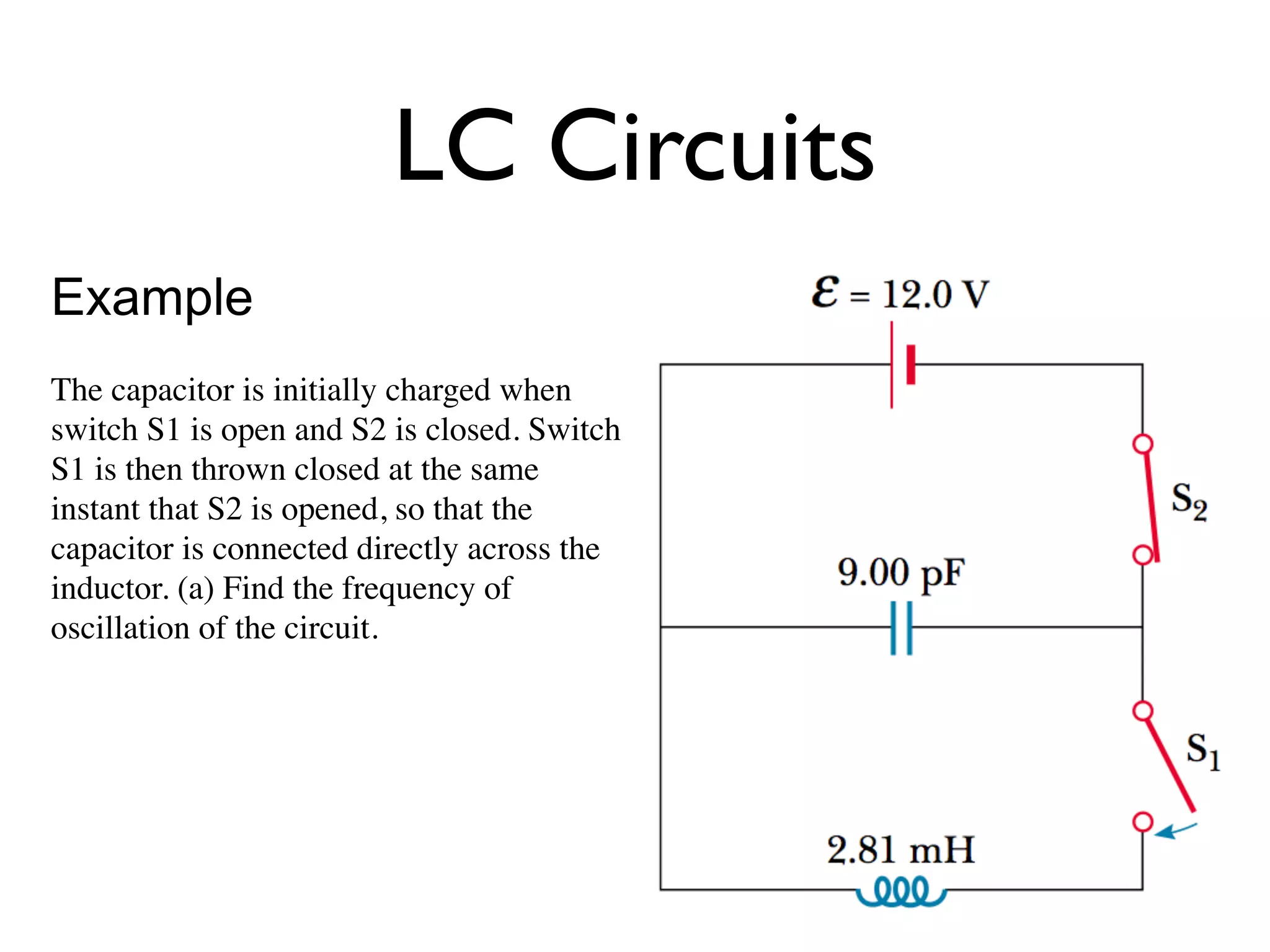
LC Circuits
Example
The capacitoris initially charged when
switch S1 is open and S2 is closed. Switch
S1 is then thrown closed at the same
instant that S2 is opened, so that the
capacitor is connected directly across the
inductor. (a) Find the frequency of
oscillation of the circuit.
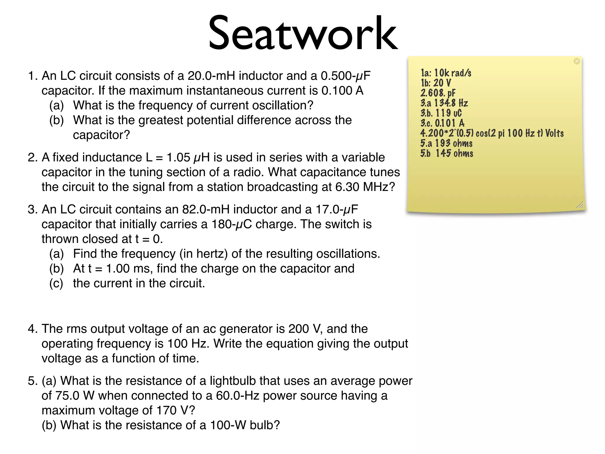
Seatwork
1. An LCcircuit consists of a 20.0-mH inductor and a 0.500-µF 1a: 10k rad/s
1b: 20 V
capacitor. If the maximum instantaneous current is 0.100 A 2.608. pF
(a) What is the frequency of current oscillation? 3.a 134.8 Hz
3.b. 119 uC
(b) What is the greatest potential difference across the 3.c. 0.101 A
capacitor? 4.200*2^(0.5) cos(2 pi 100 Hz t) Volts
5.a 193 ohms
5.b 145 ohms
2. A fixed inductance L = 1.05 µH is used in series with a variable
capacitor in the tuning section of a radio. What capacitance tunes
the circuit to the signal from a station broadcasting at 6.30 MHz?
3. An LC circuit contains an 82.0-mH inductor and a 17.0-µF
capacitor that initially carries a 180-µC charge. The switch is
thrown closed at t = 0.
(a) Find the frequency (in hertz) of the resulting oscillations.
(b) At t = 1.00 ms, find the charge on the capacitor and
(c) the current in the circuit.
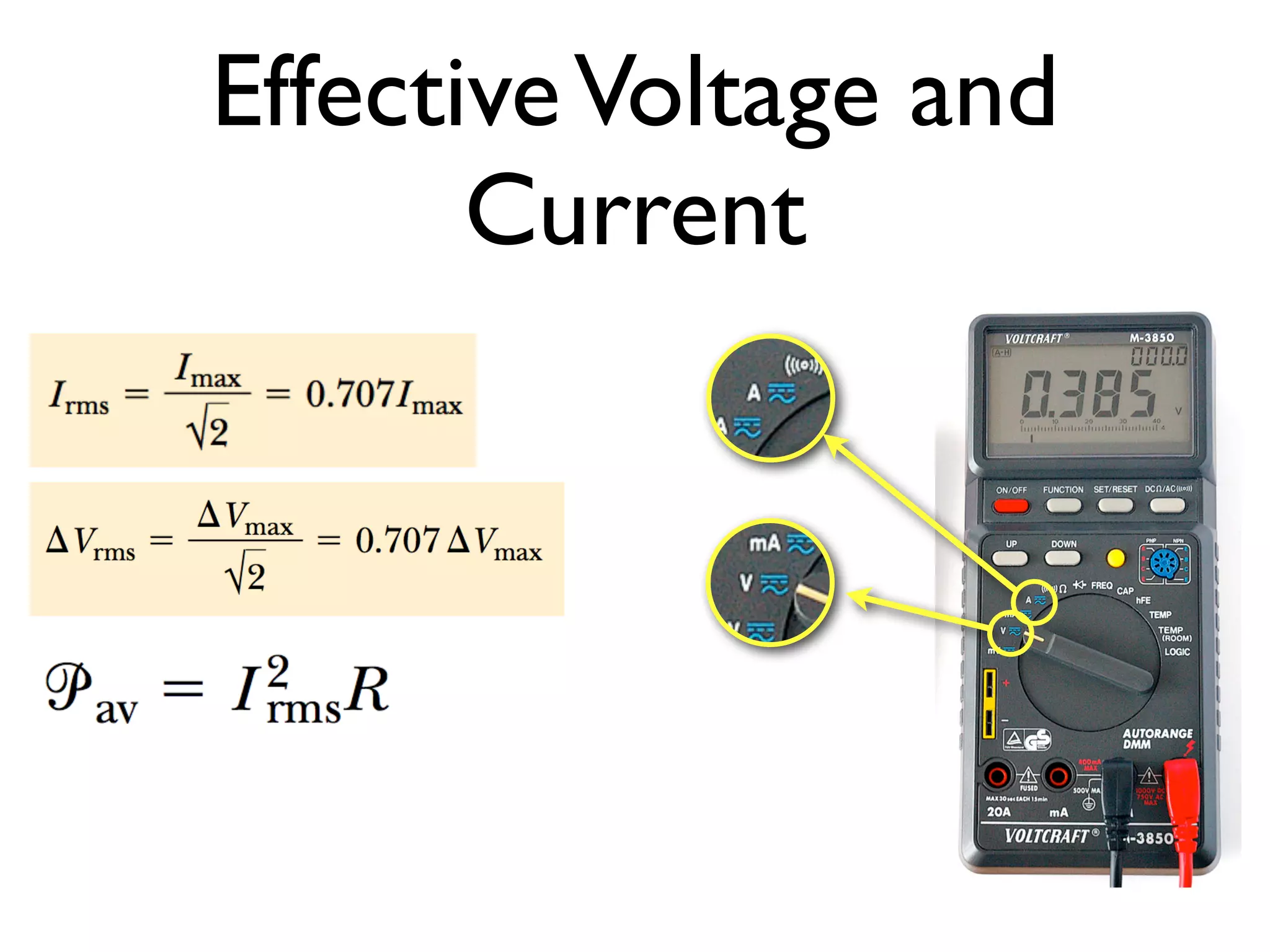
4. The rms output voltage of an ac generator is 200 V, and the
operating frequency is 100 Hz. Write the equation giving the output
voltage as a function of time.
5. (a) What is the resistance of a lightbulb that uses an average power
of 75.0 W when connected to a 60.0-Hz power source having a
maximum voltage of 170 V?
(b) What is the resistance of a 100-W bulb?


![Vibe Coding vs. Spec-Driven Development [Free Meetup]](https://cdn.slidesharecdn.com/ss_thumbnails/vibecodingvsspecdrivendevelopment-251209105622-43f455e7-thumbnail.jpg?width=640&height=640&fit=bounds)