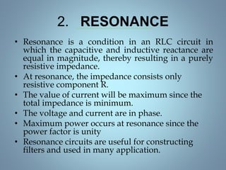
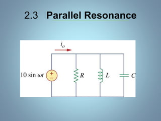
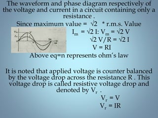
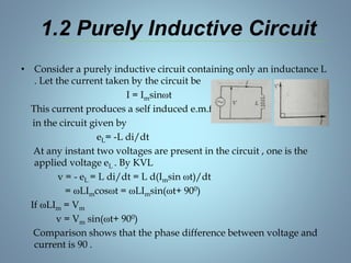
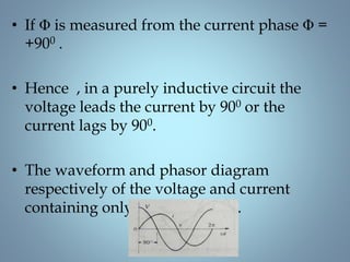
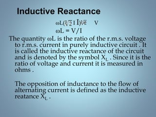
This document provides a summary of a seminar presentation on analyzing single phase AC circuits. The presentation covered various circuit elements in AC circuits including resistors, inductors, and capacitors in both series and parallel configurations. It discussed the concepts of impedance, phase relationships between voltage and current, and resonance. Resonance occurs when the inductive and capacitive reactances are equal, resulting in maximum current flow. The key topics were analyzing purely resistive, inductive, and capacitive circuits, and combinations using circuit laws and phasor diagrams.
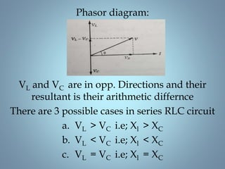
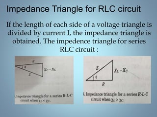
![• When XL > XC the circuit is predominantly
inductive .
• # Inductive circuits cause the current ‘lag’ the
voltage.
• V=I √[R2 + ( Xl - XC )2]
• Z = √[R2 + ( Xl - XC )2]
• When XL < XC the circuit is predominately
capacitive.
• # Capacitive circuits cause the current to ‘lead’
the voltage.
• V=I √[R2 + ( Xc - Xl )2]
• Z = √[R2 + ( Xc - XL )2]](https://image.slidesharecdn.com/pranavaccircuit-160410073708/85/Single-phase-AC-circuits-22-320.jpg)