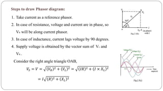
The document discusses steady state analysis of AC circuits. It covers the response of pure resistance, inductance and capacitance circuits to sinusoidal excitation. The key points are:
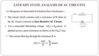
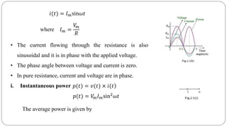
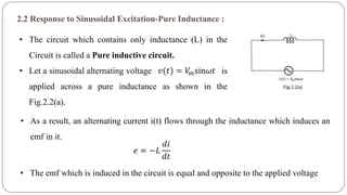
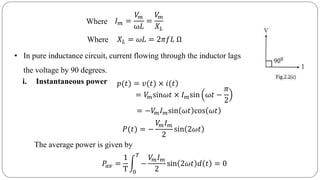
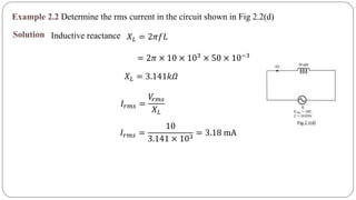
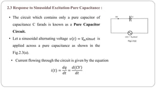
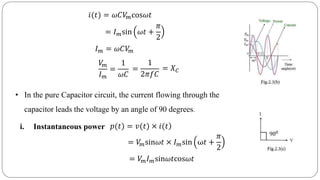
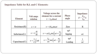
- In a pure resistance circuit, current and voltage are in phase. In pure inductance, current lags voltage by 90 degrees. In pure capacitance, current leads voltage by 90 degrees.
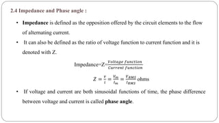
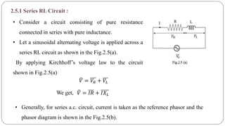
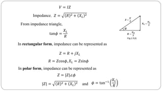
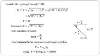
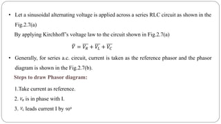
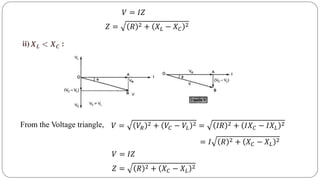
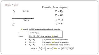
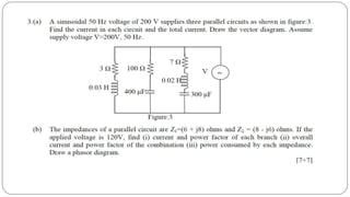
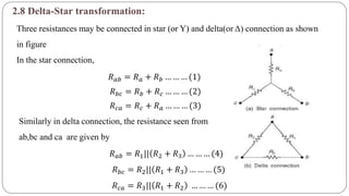
- Impedance is defined as the ratio of voltage to current. It has both magnitude and phase angle. Impedance of series R, L, and C circuits can be calculated using phasor diagrams.
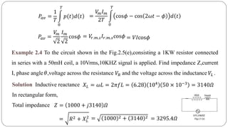
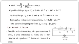
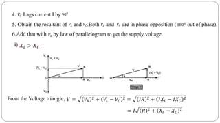
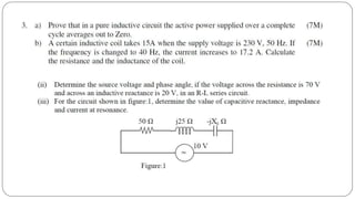
- For series RL circuits, the total impedance is the square root of the sum of the squares of resistance and reactance.
The apparatus used for switching, controlling & protecting the electrical circuits & equipments are known as switchgear.
The switchgear equipments is essentially used with switching & interrupting currents either under normal or abnormal operating condition.
It consists of devices such as switches, fuses, circuit breakers, relays etc.
Basically every electric circuit needs a switching device & a protecting device.
In this presentation, we’ll describe types of fault in power system including :
Definition of Fault in Power System
Types of Fault and
A short description of various types of Fault
Functions and Performance Requirements
Elements of an Excitation System
Types of Excitation Systems
Control and Protection Functions
Modeling of Excitation Systems
The functions of an excitation system are
to provide direct current to the synchronous generator field winding, and
to perform control and protective functions essential to the satisfactory operation of the power system
The performance requirements of the excitation system are determined by
Generator considerations:
supply and adjust field current as the generator output varies within its continuous capability
respond to transient disturbances with field forcing consistent with the generator short term capabilities:
rotor insulation failure due to high field voltage
rotor heating due to high field current
stator heating due to high VAR loading
heating due to excess flux (volts/Hz)
Power system considerations:
contribute to effective control of system voltage and improvement of system stability
Transients
Voltage surge or Transient Voltage
Types of Power System Transients
Causes of System transients
Overvoltage due to external causes
Overvoltage due to internal causes
Transients in Simple Circuit
D. C. Source & А.С. Source
Travelling Waves on Transmission Line
Wave equation
Travelling wave with open end line & Short Circuited Line
Reflection and Refraction Coefficient
Line Connected to a Cable
Line terminated Through Capacitance
Capacitor Connection at a T.L.
Attenuation of Travelling Waves
Introduction, Op-Amp, signal conditioning, filters, non linear op-amps, signal sources, voltage regulators, ic power amplifiers, tuned amplifiers, d/a, a/d converters, simulation studies
Alternating current (AC), is an electric current in which the flow of electric charge periodically reverses direction, whereas in direct current (DC, also dc), the flow of electric charge is only in one direction.
Sachpazis:Terzaghi Bearing Capacity Estimation in simple terms with Calculati...Dr.Costas Sachpazis
Terzaghi's soil bearing capacity theory, developed by Karl Terzaghi, is a fundamental principle in geotechnical engineering used to determine the bearing capacity of shallow foundations. This theory provides a method to calculate the ultimate bearing capacity of soil, which is the maximum load per unit area that the soil can support without undergoing shear failure. The Calculation HTML Code included.
Literature Review Basics and Understanding Reference Management.pptxDr Ramhari Poudyal
Three-day training on academic research focuses on analytical tools at United Technical College, supported by the University Grant Commission, Nepal. 24-26 May 2024
Student information management system project report ii.pdfKamal Acharya
Our project explains about the student management. This project mainly explains the various actions related to student details. This project shows some ease in adding, editing and deleting the student details. It also provides a less time consuming process for viewing, adding, editing and deleting the marks of the students.
Harnessing WebAssembly for Real-time Stateless Streaming PipelinesChristina Lin
Traditionally, dealing with real-time data pipelines has involved significant overhead, even for straightforward tasks like data transformation or masking. However, in this talk, we’ll venture into the dynamic realm of WebAssembly (WASM) and discover how it can revolutionize the creation of stateless streaming pipelines within a Kafka (Redpanda) broker. These pipelines are adept at managing low-latency, high-data-volume scenarios.
Final project report on grocery store management system..pdfKamal Acharya
In today’s fast-changing business environment, it’s extremely important to be able to respond to client needs in the most effective and timely manner. If your customers wish to see your business online and have instant access to your products or services.
Online Grocery Store is an e-commerce website, which retails various grocery products. This project allows viewing various products available enables registered users to purchase desired products instantly using Paytm, UPI payment processor (Instant Pay) and also can place order by using Cash on Delivery (Pay Later) option. This project provides an easy access to Administrators and Managers to view orders placed using Pay Later and Instant Pay options.
In order to develop an e-commerce website, a number of Technologies must be studied and understood. These include multi-tiered architecture, server and client-side scripting techniques, implementation technologies, programming language (such as PHP, HTML, CSS, JavaScript) and MySQL relational databases. This is a project with the objective to develop a basic website where a consumer is provided with a shopping cart website and also to know about the technologies used to develop such a website.
This document will discuss each of the underlying technologies to create and implement an e- commerce website.
Cosmetic shop management system project report.pdfKamal Acharya
Buying new cosmetic products is difficult. It can even be scary for those who have sensitive skin and are prone to skin trouble. The information needed to alleviate this problem is on the back of each product, but it's thought to interpret those ingredient lists unless you have a background in chemistry.
Instead of buying and hoping for the best, we can use data science to help us predict which products may be good fits for us. It includes various function programs to do the above mentioned tasks.
Data file handling has been effectively used in the program.
The automated cosmetic shop management system should deal with the automation of general workflow and administration process of the shop. The main processes of the system focus on customer's request where the system is able to search the most appropriate products and deliver it to the customers. It should help the employees to quickly identify the list of cosmetic product that have reached the minimum quantity and also keep a track of expired date for each cosmetic product. It should help the employees to find the rack number in which the product is placed.It is also Faster and more efficient way.
6th International Conference on Machine Learning & Applications (CMLA 2024)ClaraZara1
6th International Conference on Machine Learning & Applications (CMLA 2024) will provide an excellent international forum for sharing knowledge and results in theory, methodology and applications of on Machine Learning & Applications.
KuberTENes Birthday Bash Guadalajara - K8sGPT first impressionsVictor Morales
K8sGPT is a tool that analyzes and diagnoses Kubernetes clusters. This presentation was used to share the requirements and dependencies to deploy K8sGPT in a local environment.
An Approach to Detecting Writing Styles Based on Clustering Techniquesambekarshweta25
An Approach to Detecting Writing Styles Based on Clustering Techniques
Authors:
-Devkinandan Jagtap
-Shweta Ambekar
-Harshit Singh
-Nakul Sharma (Assistant Professor)
Institution:
VIIT Pune, India
Abstract:
This paper proposes a system to differentiate between human-generated and AI-generated texts using stylometric analysis. The system analyzes text files and classifies writing styles by employing various clustering algorithms, such as k-means, k-means++, hierarchical, and DBSCAN. The effectiveness of these algorithms is measured using silhouette scores. The system successfully identifies distinct writing styles within documents, demonstrating its potential for plagiarism detection.
Introduction:
Stylometry, the study of linguistic and structural features in texts, is used for tasks like plagiarism detection, genre separation, and author verification. This paper leverages stylometric analysis to identify different writing styles and improve plagiarism detection methods.
Methodology:
The system includes data collection, preprocessing, feature extraction, dimensional reduction, machine learning models for clustering, and performance comparison using silhouette scores. Feature extraction focuses on lexical features, vocabulary richness, and readability scores. The study uses a small dataset of texts from various authors and employs algorithms like k-means, k-means++, hierarchical clustering, and DBSCAN for clustering.
Results:
Experiments show that the system effectively identifies writing styles, with silhouette scores indicating reasonable to strong clustering when k=2. As the number of clusters increases, the silhouette scores decrease, indicating a drop in accuracy. K-means and k-means++ perform similarly, while hierarchical clustering is less optimized.
Conclusion and Future Work:
The system works well for distinguishing writing styles with two clusters but becomes less accurate as the number of clusters increases. Future research could focus on adding more parameters and optimizing the methodology to improve accuracy with higher cluster values. This system can enhance existing plagiarism detection tools, especially in academic settings.
Online aptitude test management system project report.pdfKamal Acharya
The purpose of on-line aptitude test system is to take online test in an efficient manner and no time wasting for checking the paper. The main objective of on-line aptitude test system is to efficiently evaluate the candidate thoroughly through a fully automated system that not only saves lot of time but also gives fast results. For students they give papers according to their convenience and time and there is no need of using extra thing like paper, pen etc. This can be used in educational institutions as well as in corporate world. Can be used anywhere any time as it is a web based application (user Location doesn’t matter). No restriction that examiner has to be present when the candidate takes the test.
Every time when lecturers/professors need to conduct examinations they have to sit down think about the questions and then create a whole new set of questions for each and every exam. In some cases the professor may want to give an open book online exam that is the student can take the exam any time anywhere, but the student might have to answer the questions in a limited time period. The professor may want to change the sequence of questions for every student. The problem that a student has is whenever a date for the exam is declared the student has to take it and there is no way he can take it at some other time. This project will create an interface for the examiner to create and store questions in a repository. It will also create an interface for the student to take examinations at his convenience and the questions and/or exams may be timed. Thereby creating an application which can be used by examiners and examinee’s simultaneously.
Examination System is very useful for Teachers/Professors. As in the teaching profession, you are responsible for writing question papers. In the conventional method, you write the question paper on paper, keep question papers separate from answers and all this information you have to keep in a locker to avoid unauthorized access. Using the Examination System you can create a question paper and everything will be written to a single exam file in encrypted format. You can set the General and Administrator password to avoid unauthorized access to your question paper. Every time you start the examination, the program shuffles all the questions and selects them randomly from the database, which reduces the chances of memorizing the questions.
Forklift Classes Overview by Intella PartsIntella Parts
Discover the different forklift classes and their specific applications. Learn how to choose the right forklift for your needs to ensure safety, efficiency, and compliance in your operations.
For more technical information, visit our website https://intellaparts.com
NUMERICAL SIMULATIONS OF HEAT AND MASS TRANSFER IN CONDENSING HEAT EXCHANGERS...ssuser7dcef0
Power plants release a large amount of water vapor into the
atmosphere through the stack. The flue gas can be a potential
source for obtaining much needed cooling water for a power
plant. If a power plant could recover and reuse a portion of this
moisture, it could reduce its total cooling water intake
requirement. One of the most practical way to recover water
from flue gas is to use a condensing heat exchanger. The power
plant could also recover latent heat due to condensation as well
as sensible heat due to lowering the flue gas exit temperature.
Additionally, harmful acids released from the stack can be
reduced in a condensing heat exchanger by acid condensation. reduced in a condensing heat exchanger by acid condensation.
Condensation of vapors in flue gas is a complicated
phenomenon since heat and mass transfer of water vapor and
various acids simultaneously occur in the presence of noncondensable
gases such as nitrogen and oxygen. Design of a
condenser depends on the knowledge and understanding of the
heat and mass transfer processes. A computer program for
numerical simulations of water (H2O) and sulfuric acid (H2SO4)
condensation in a flue gas condensing heat exchanger was
developed using MATLAB. Governing equations based on
mass and energy balances for the system were derived to
predict variables such as flue gas exit temperature, cooling
water outlet temperature, mole fraction and condensation rates
of water and sulfuric acid vapors. The equations were solved
using an iterative solution technique with calculations of heat
and mass transfer coefficients and physical properties.
2. CONTENTS
2.STEADY STATE ANALYSIS OF AC CIRCUITS
2.1 Response to Sinusoidal Excitation-Pure Resistance
2.2 Response to Sinusoidal Excitation-Pure Inductance
2.3 Response to Sinusoidal Excitation-Pure Capacitance
2.4 Impedance concept and phase angle
2.5 Series Circuits-RL,RC,RLC
2.6 Steady state AC Mesh Analysis
2.7 Steady state AC Nodal Analysis
2.8 Star-Delta &Delta-Star Transformation
3. 2.STEADY STATE ANALYSIS OFAC CIRCUITS
2.1 Response to Sinusoidal Excitation-Pure Resistance :
• The circuit which contains only a resistance of R ohms in
the AC circuit is known as Pure Resistive AC Circuit.
• Let a sinusoidal alternating voltage is
applied across a pure resistance as shown in the Fig.2.1(a).
𝑣(𝑡) = 𝑉𝑚sin𝜔𝑡
• The current flowing through the resistance R is
𝑖(𝑡) =
)𝑣(𝑡
𝑅
=
𝑉𝑚
𝑅
sin𝜔𝑡
4. where
• The current flowing through the resistance is also
sinusoidal and it is in phase with the applied voltage.
• The phase angle between voltage and current is zero.
• In pure resistance, current and voltage are in phase.
i. Instantaneous power
𝑖(𝑡) = 𝐼 𝑚sin𝜔𝑡
𝐼 𝑚 =
𝑉𝑚
𝑅
)𝑝(𝑡) = 𝑣(𝑡) × 𝑖(𝑡
𝑝(𝑡) = 𝑉𝑚 𝐼 𝑚sin2
𝜔𝑡
The average power is given by
5. 𝑃𝑎𝑣 =
1
𝑇
0
𝑇
𝑝(𝑡)𝑑𝑡
=
1
𝑇
0
𝑇
𝑉𝑚 𝐼 𝑚
2
−
𝑉𝑚 𝐼 𝑚
2
cos2𝜔𝑡 𝑑 𝑡
=
𝑉𝑚 𝐼 𝑚
2
=
𝑉𝑚
2
𝐼 𝑚
2
𝑃𝑎𝑣 = 𝑉𝑟.𝑚.𝑠 𝐼𝑟.𝑚.𝑠
Where Pav is average power
Vr.m.s is root mean square value of supply voltage
Ir.m.s is root mean square value of the current
6. Example 2.1 A sinusoidal voltage is applied to the resistive circuit shown in
Fig.2.1(d).Determine the following values
(a) (b) (c) (d)𝐼𝑟𝑚𝑠 𝐼 𝑎𝑣 𝐼 𝑝 𝐼 𝑝𝑝
Solution The function given to the circuit shown is
The current passing through the resistor is
𝑣(𝑡) = 𝑉𝑝sin𝜔𝑡 = 20sin𝜔𝑡
𝑖(𝑡) =
)𝑣(𝑡
𝑅
=
20
2 × 10³
sin𝜔𝑡 = 10 × 10−3sin𝜔𝑡
7. Peak value
Peak to peak value
Rms value = 0.707×10 mA=7.07 mA
𝐼 𝑝=10 mA
𝐼 𝑝𝑝=20 mA
𝐼𝑟𝑚𝑠=
𝐼 𝑝
2
Average Value =
1
𝜋
0
𝜋
𝐼 𝑝sin𝜔𝑡 𝑑𝜔𝑡𝐼 𝑎𝑣
𝐼 𝑎𝑣 =
1
𝜋
−𝐼 𝑝cos𝜔𝑡
0
𝜋
= 0.637 𝐼 𝑃
= 0.637 × 10𝑚𝐴 = 6.37𝑚𝐴
8. 2.2 Response to Sinusoidal Excitation-Pure Inductance :
• The circuit which contains only inductance (L) in the
Circuit is called a Pure inductive circuit.
• Let a sinusoidal alternating voltage is
applied across a pure inductance as shown in the
Fig.2.2(a).
𝑣(𝑡) = 𝑉𝑚sin𝜔𝑡
• As a result, an alternating current i(t) flows through the inductance which induces an
emf in it.
𝑒 = −𝐿
𝑑𝑖
𝑑𝑡
• The emf which is induced in the circuit is equal and opposite to the applied voltage
10. Where
𝐼 𝑚 =
𝑉𝑚
ω𝐿
=
𝑉𝑚
𝑋 𝐿
Where
𝑋 𝐿 = 𝜔𝐿 = 2𝜋𝑓𝐿 Ω
• In pure inductance circuit, current flowing through the inductor lags
the voltage by 90 degrees.
i. Instantaneous power )𝑝(𝑡) = 𝑣(𝑡) × 𝑖(𝑡
= 𝑉𝑚sin𝜔𝑡 × 𝐼 𝑚sin ω𝑡 −
𝜋
2
= −𝑉𝑚 𝐼 𝑚sin 𝜔𝑡 cos 𝜔𝑡
𝑃(𝑡) = −
𝑉𝑚 𝐼 𝑚
2
sin 2𝜔𝑡
The average power is given by
𝑃𝑎𝑣 =
1
T 0
𝑇
−
𝑉𝑚 𝐼 𝑚
2
sin 2𝜔𝑡 𝑑 𝑡 = 0
11. ii. The energy stored in a pure inductor is obtained by integrating power expression
over a positive half cycle of power variation.
Energy Stored
=
𝑉𝑚 𝐼 𝑚
2𝜔
=
1
2
𝐿𝐼 𝑚
2
Energy stored in a pure inductor =
1
2
𝐿𝐼 𝑚
2 𝐽𝑜𝑢𝑙𝑒𝑠
= −
𝑉𝑚 𝐼 𝑚
2
−cos2𝜔𝑡
2𝜔 𝑇
2
𝑇
𝑊 =
𝑇
2
𝑇
𝑃 𝑡 𝑑𝑡 = −
𝑉𝑚 𝐼 𝑚
2
𝑇
2
𝑇
sin2𝜔𝑡 𝑑𝑡
12. Example 2.2 Determine the rms current in the circuit shown in Fig 2.2(d)
Solution Inductive reactance 𝑋 𝐿 = 2𝜋𝑓𝐿
= 2𝜋 × 10 × 103
× 50 × 10−3
𝑋 𝐿 = 3.141𝑘𝛺
𝐼𝑟𝑚𝑠 =
𝑉𝑟𝑚𝑠
𝑋 𝐿
𝐼𝑟𝑚𝑠 =
10
3.141 × 103
= 3.18 mA
13. 2.3 Response to Sinusoidal Excitation-Pure Capacitance :
• The circuit which contains only a pure capacitor of
capacitance C farads is known as a Pure Capacitor
Circuit.
• Let a sinusoidal alternating voltage is
applied across a pure capacitance as shown in the
Fig.2.3(a).
𝑣 𝑡 = 𝑉𝑚sin𝜔𝑡
• Current flowing through the circuit is given by the equation
𝑖(𝑡) =
𝑑𝑞
𝑑𝑡
=
)𝑑(𝐶𝑉
𝑑𝑡
14. 𝑖(𝑡) = 𝜔𝐶𝑉𝑚cos𝜔𝑡
= 𝐼 𝑚sin 𝜔𝑡 +
𝜋
2
𝐼 𝑚 = 𝜔𝐶𝑉𝑚
𝑉𝑚
𝐼 𝑚
=
1
𝜔𝐶
=
1
2𝜋𝑓𝐶
= 𝑋 𝐶
• In the pure Capacitor circuit, the current flowing through the
capacitor leads the voltage by an angle of 90 degrees.
i. Instantaneous power )𝑝(𝑡) = 𝑣(𝑡) × 𝑖(𝑡
= 𝑉𝑚sin𝜔𝑡 × 𝐼 𝑚sin ω𝑡 +
𝜋
2
= 𝑉𝑚 𝐼 𝑚sin𝜔𝑡cos𝜔𝑡
15. 𝑝(𝑡) =
𝑉𝑚 𝐼 𝑚
2
sin2𝜔𝑡
The average power is given by
𝑃𝑎𝑣 =
1
𝑇 0
T
𝑉𝑚 𝐼 𝑚
2
sin 2𝜔𝑡 𝑑 𝜔𝑡 = 0
ii. The energy stored in a pure capacitor is obtained by integrating power
expression over a positive half cycle of power variation.
Energy Stored = 𝑊 =
0
𝑇 2
)𝑝(𝑡 𝑑𝑡 =
𝑉𝑚 𝐼 𝑚
2
0
𝑇 2
sin2𝜔𝑡 𝑑𝑡
=
𝑉𝑚 𝐼 𝑚
2𝜔
=
1
2
𝐶𝑉𝑚
2
Energy stored in a pure capacitor=
1
2
𝐶𝑉𝑚
2 Joules
16. Example 2.3 Determine the rms current in the circuit shown in Fig 2.3(d)
Solution Capacitive reactance 𝑋 𝐶 =
1
2𝜋𝑓𝐶
=
1
2𝜋 × 5 × 103 × 0.01 × 10−6
𝑋 𝐶 = 3.18𝐾𝛺
𝐼𝑟𝑚𝑠 =
𝑉𝑟𝑚𝑠
𝑋 𝐶
𝐼𝑟𝑚𝑠 =
5
3.18𝐾
= 1.57 mA
17. 2.4 Impedance and Phase angle :
• Impedance is defined as the opposition offered by the circuit elements to the flow
of alternating current.
• It can also be defined as the ratio of voltage function to current function and it is
denoted with Z.
• If voltage and current are both sinusoidal functions of time, the phase difference
between voltage and current is called phase angle.
Impedance=Z=
𝑉𝑜𝑙𝑡𝑎𝑔𝑒 𝑓𝑢𝑛𝑐𝑡𝑖𝑜𝑛
𝐶𝑢𝑟𝑟𝑒𝑛𝑡 𝑓𝑢𝑛𝑐𝑡𝑖𝑜𝑛
𝑍 =
𝑣
𝑖
=
𝑉 𝑚
𝐼 𝑚
=
𝑉 𝑅𝑀𝑆
𝐼 𝑅𝑀𝑆
ohms
19. 2.5.1 Series RL Circuit :
• Consider a circuit consisting of pure resistance
connected in series with pure inductance.
• Let a sinusoidal alternating voltage is applied across a
series RL circuit as shown in the Fig.2.5(a).
By applying Kirchhoff’s voltage law to the circuit
shown in Fig.2.5(a)
We get,
𝑉 = 𝑉𝑅 + 𝑉𝐿
𝑉 = 𝐼𝑅 + 𝐼𝑋 𝐿
• Generally, for series a.c. circuit, current is taken as the reference phasor and the
phasor diagram is shown in the Fig.2.5(b).
20. Steps to draw Phasor diagram:
1. Take current as a reference phasor.
2. In case of resistance, voltage and current are in phase, so
VR will be along current phasor.
3. In case of inductance, current lags voltage by 90 degrees.
4. Supply voltage is obtained by the vector sum of VL and
VR .
𝑉 = 𝑉𝑅
2 + 𝑉𝐿
2 = 𝐼𝑅 2 + 𝐼 × 𝑋 𝐿
2
= 𝐼 𝑅 2 + 𝑋 𝐿
2
𝑉𝑆 =
Consider the right angle triangle OAB,
21. 𝑉 = 𝐼𝑍
𝑍 = 𝑅 2 + 𝑋 𝐿
2Impedance,
From impedance triangle,
tan𝜙 =
𝑋 𝐿
𝑅
In polar form, impedance can be represented as
𝑍 = |𝑍|∠𝜙
𝑍 = 𝑅 + 𝑗𝑋 𝐿
In rectangular form, impedance can be represented as
|𝑍| = 𝑅 2 + 𝑋 𝐿
2 𝜙 = tan−1
𝑋 𝐿
𝑅and
𝑅 = 𝑍cos𝜙, 𝑋 𝐿 = 𝑍sin𝜙
22. Instantaneous power )𝑝(𝑡) = 𝑣(𝑡) × 𝑖(𝑡
Where and𝑣(𝑡) = 𝑉𝑚sin𝜔𝑡 )𝑖(𝑡) = 𝐼 𝑚sin(𝜔𝑡 − 𝜙
𝑝(𝑡) = 𝑉𝑚sin𝜔𝑡 × )𝐼 𝑚sin(𝜔𝑡 − 𝜙
𝑝(𝑡) =
𝑉𝑚 𝐼 𝑚
2
2sin 𝜔𝑡 − 𝜙 sin𝜔𝑡
𝑝(𝑡) =
𝑉𝑚
2
𝐼 𝑚
2
)cos𝜙 − cos(2𝜔𝑡 − 𝜙
𝑝(𝑡) =
𝑉𝑚
2
𝐼 𝑚
2
cos𝜙 −
𝑉𝑚
2
𝐼 𝑚
2
cos 2𝜔𝑡 − 𝜙
The average power consumed in the circuit over one complete cycle is given by
23. 𝑃𝑎𝑣 =
1
𝑇
0
𝑇
𝑝(𝑡)𝑑 𝑡 =
𝑉𝑚 𝐼 𝑚
2𝑇
0
𝑇
cos𝜙 − cos 2𝜔𝑡 − 𝜙 𝑑 𝑡
= 𝑉𝑟.𝑚.𝑠 𝐼𝑟.𝑚.𝑠cos𝜙 = 𝑉𝐼cos𝜙𝑃𝑎𝑣 =
𝑉𝑚
2
𝐼 𝑚
2
cos𝜙
Example 2.4 To the circuit shown in the Fig.2.5(e),consisting a 1KW resistor connected
in series with a 50mH coil, a 10Vrms,10KHZ signal is applied. Find impedance Z,current
I, phase angle ,voltage across the resistance and the voltage across the inductance .𝑉𝑅 𝑉𝐿
Solution Inductive reactance
In rectangular form,
Total impedance
𝑋 𝐿 = 𝜔𝐿 = 2𝜋𝑓𝐿 = 6.28 104 50 × 10−3 = 3140𝛺
𝑍 = 1000 + 𝑗3140 𝛺
= 𝑅2 + 𝑋 𝐿
2 = 1000 2 + 3140 2 = 3295.4𝛺
𝜃
24. Current
Phase angle
Therefore, in polar form in total impedance
Voltage across the resistance
Voltage across the inductance
𝐼 =
𝑉𝑆
𝑍
=
10
3295.4
= 3.03𝑚𝐴
𝜃 = tan−1
𝑋 𝐿
𝑅
= tan−1
3140
1000
= 72.330
𝑍 = 3295.4∠72.330
𝑉𝑅 = 𝐼𝑅 = 3.03 × 10−3
× 1000 = 3.03𝑉
𝑉𝐿 = 𝐼𝑋 𝐿 = 3.03 × 10−3 × 3140 = 9.51𝑉
Example 2.5 Determine the source voltage and the phase angle, if voltage across the
resistance is 70V and the voltage across the inductance is 20V as shown in Fig.
Solution Source voltage is given by 𝑉𝑆 = 𝑉𝑅
2
+ 𝑉𝐿
2
= 70 2 + 20 2 = 72.8𝑉
25. The angle between the current and source voltage is
𝜃 = tan−1
20
70
= 15.940
2.5.2 Series RC Circuit :
• Consider a circuit consisting of pure resistance R ohms
connected in series with a pure capacitor of capacitance C
farads.
• Let a sinusoidal alternating voltage is applied across a series
RC circuit as shown in the Fig.2.6(a).
By applying Kirchhoff’s voltage law to the circuit shown in Fig.2.6(a)
𝑉 = 𝑉𝑅 + 𝑉𝐶
26. 𝑉 = 𝐼𝑅 + 𝐼𝑋 𝐶
• Generally, for series a.c. circuit, current is taken as the reference phasor and the
phasor diagram is shown in the Fig.2.6(b).
Steps to draw Phasor diagram:
1. Take current as a reference phasor.
2. In case of resistance, voltage and current are in phase, so VR
will be along current phasor.
3. In case of pure capacitance, current leads the voltage by 90
degrees.
4. Supply voltage is attained by the vector sum of VC and VR .
28. In polar form, impedance can be represented as
𝑍 = |𝑍|∠𝜙
|𝑍| = 𝑅 2 + 𝑋 𝐶
2 and 𝜙 = tan−1
𝑋 𝐶
𝑅
Instantaneous power )𝑝(𝑡) = 𝑣(𝑡) × 𝑖(𝑡
Where and𝑣(𝑡) = 𝑉𝑚sin𝜔𝑡 )𝑖(𝑡) = 𝐼 𝑚sin(𝜔𝑡 + 𝜙
𝑝(𝑡) = 𝑉𝑚sin𝜔𝑡 × )𝐼 𝑚sin(𝜔𝑡 + 𝜙
𝑝(𝑡) =
𝑉𝑚 𝐼 𝑚
2
2sin 𝜔𝑡 + 𝜙 sin𝜔𝑡
𝑝(𝑡) =
𝑉𝑚
2
𝐼 𝑚
2
)cos𝜙 − cos(2𝜔𝑡 + 𝜙
The average power consumed in the circuit over one complete cycle is given by
29. 𝑃𝑎𝑣 =
1
𝑇
0
𝑇
𝑝(𝑡)𝑑 𝜔𝑡 =
𝑉𝑚 𝐼 𝑚
2𝑇
0
𝑇
cos𝜙 − cos 2𝜔𝑡 + 𝜙 𝑑 𝜔𝑡
= 𝑉𝑟.𝑚.𝑠 𝐼𝑟.𝑚.𝑠cos𝜙 = 𝑉𝐼cos𝜙𝑃𝑎𝑣 =
𝑉𝑚
2
𝐼 𝑚
2
cos𝜙
Example 2.6 Determine the source voltage and phase angle when the voltage across the
Resistor is 20V and the capacitor is 30V as shown in Fig.
Solution Source voltage is given by
𝑉𝑆 = 𝑉𝑅
2
+ 𝑉𝐶
2
= 20 2 + 30 2 = 36𝑉
The angle between the current and source voltage is
𝜃 = tan−1
30
20
= 56.30
30. Example 2.7 A sine wave generator supplies a 500Hz,10V rms signal to a 2kΩ resistor in
Series with a 0.1μF capacitor as shown in Fig.Determine the
total impedance Z,current I, phase angle ϴ,capacitive voltage
and resistive voltage .𝑉𝐶 𝑉𝑅
Solution Capacitive reactance
𝑋 𝐶 =
1
2𝜋𝑓𝐶
=
1
6.28 × 500 × 0.1 × 10−6
= 3184.7𝛺
Total impedance 𝑍 = 2000 − 𝑗3184.7 𝛺
𝑍 = 2000 2 + 3184.7 2 = 3760.6𝛺
Phase angle 𝜃 = tan−1
−𝑋 𝐶
𝑅
= tan−1
−3184.7
2000
= −57.870
31. Current 𝐼 =
𝑉𝑆
𝑍
=
10
3760.6
= 2.66𝑚𝐴
Capacitive Voltage 𝑉𝐶 = 𝐼𝑋 𝐶 = 2.66 × 10−3 × 3184.7 = 8.47𝑉
Resistive Voltage 𝑉𝑅 = 𝐼𝑅 = 2.66 × 10−3 × 2000 = 5.32𝑉
Total applied voltage in rectangular form, 𝑉𝑆 = 5.32 − 𝑗8.47𝑉
Total applied voltage in polar form, 𝑉𝑆 = 10∠ − 57.870 𝑉
2.5.3 Series RLC Circuit :
• Consider a circuit consisting of a pure resistance R
ohms, a pure inductance L Henry and a pure
capacitor of capacitance C farads are connected in
series.
32. • Let a sinusoidal alternating voltage is applied across a series RLC circuit as shown in the
Fig.2.7(a)
By applying Kirchhoff’s voltage law to the circuit shown in Fig.2.7(a)
𝑉 = 𝑉𝑅 + 𝑉𝐿 + 𝑉𝐶
• Generally, for series a.c. circuit, current is taken as the reference phasor and the phasor
diagram is shown in the Fig.2.7(b).
Steps to draw Phasor diagram:
1.Take current as reference.
2. is in phase with I.
3. leads current I by
𝑉𝑅
𝑉𝐿 900
33. 4. Lags current I by
5. Obtain the resultant of and .Both and are in phase opposition ( out of phase).
6.Add that with by law of parallelogram to get the supply voltage.
𝑉𝐶 900
𝑉𝐿 𝑉𝐶 𝑉𝐿 𝑉𝐶 1800
𝑉𝑅
i) :𝑿 𝑳 > 𝑿 𝑪
𝑉 = 𝑉𝑅
2 + 𝑉𝐿 − 𝑉𝐶
2 = 𝐼𝑅 2 + 𝐼𝑋 𝐿 − 𝐼𝑋 𝐶
2
= 𝐼 𝑅 2 + 𝑋 𝐿 − 𝑋 𝐶
2
From the Voltage triangle,
43. 2.6 Steady State AC Mesh Analysis:
A mesh is defined as a loop which does not contain any other loops within it.
Number of equations=branches-(nodes-1)
M=B-(N-1)
By applying Kirchhoff’s voltage law around the first mesh
𝑉1 = 𝐼1 𝑍1 + 𝐼1 − 𝐼2 𝑍2
By applying Kirchhoff’s voltage law around the second mesh
𝑍2 𝐼2 − 𝐼1 + 𝑍3 𝐼2 = 0
47. 2.7 Steady State AC Nodal Analysis:
• In general, in a N node circuit, one of the nodes is choosen as reference or datum node,
then it is possible to write N-1 nodal equations by assuming N-1 node voltages.
• The node voltage is the voltage of a given node with respect to one particular node,
called the reference node (which is assumed at zero potential).
𝑉𝑎 − 𝑉1
𝑍1
+
𝑉𝑎
𝑍2
+
𝑉𝑎 − 𝑉𝑏
𝑍3
= 0
−𝑉1
𝑍1
+ 𝑉𝑎
1
𝑍1
+
1
𝑍2
+
1
𝑍3
−
𝑉𝑏
𝑍3
= 0 … … … (1)
𝑉𝑏 − 𝑉𝑎
𝑍3
+
𝑉𝑏
𝑍4
+
𝑉𝑏
𝑍5 + 𝑍6
= 0
−
𝑉𝑎
𝑍3
+ 𝑉𝑏
1
𝑍3
+
1
𝑍4
+
1
𝑍5 + 𝑍6
= 0 … … … (2)
48.
49.
50.
51.
52.
53. 2.8 Delta-Star transformation:
Three resistances may be connected in star (or Y) and delta(or Δ) connection as shown
in figure
In the star connection,
𝑅 𝑎𝑏 = 𝑅 𝑎 + 𝑅 𝑏 … … … (1)
𝑅 𝑏𝑐 = 𝑅 𝑏 + 𝑅 𝑐 … … … (2)
𝑅 𝑐𝑎 = 𝑅 𝑐 + 𝑅 𝑎 … … … (3)
Similarly in delta connection, the resistance seen from
ab,bc and ca are given by
𝑅 𝑎𝑏 = 𝑅1|| 𝑅2 + 𝑅3 … … … (4)
𝑅 𝑏𝑐 = 𝑅2|| 𝑅1 + 𝑅3 … … … (5)
𝑅 𝑐𝑎 = 𝑅3|| 𝑅1 + 𝑅2 … … … (6)