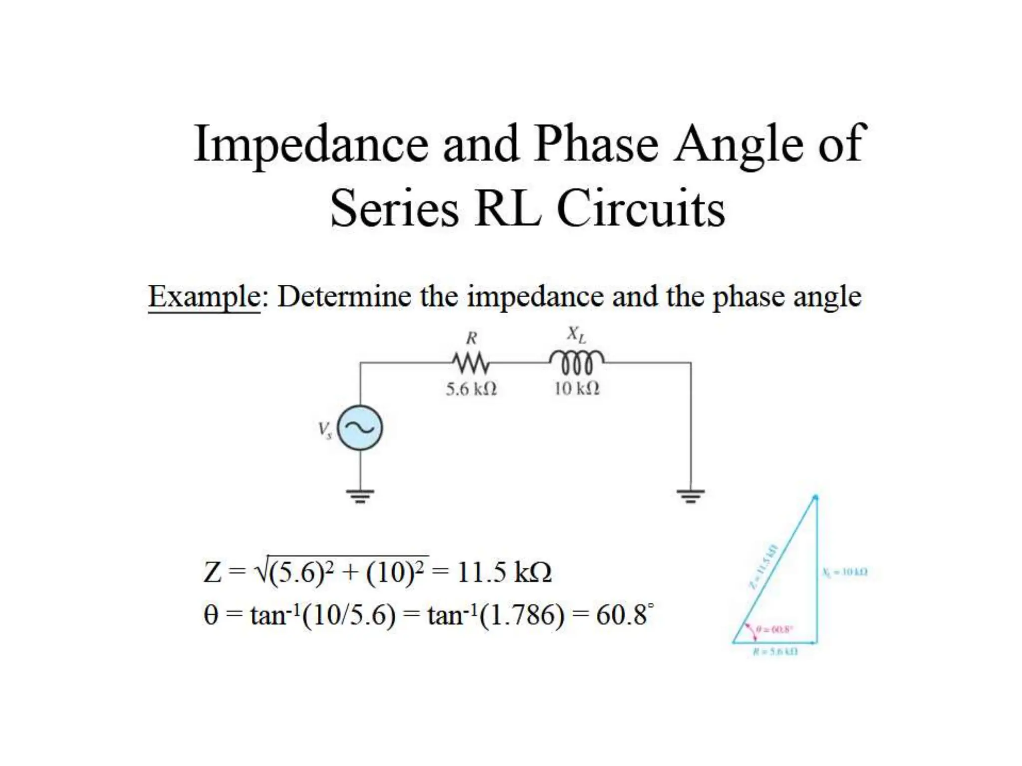
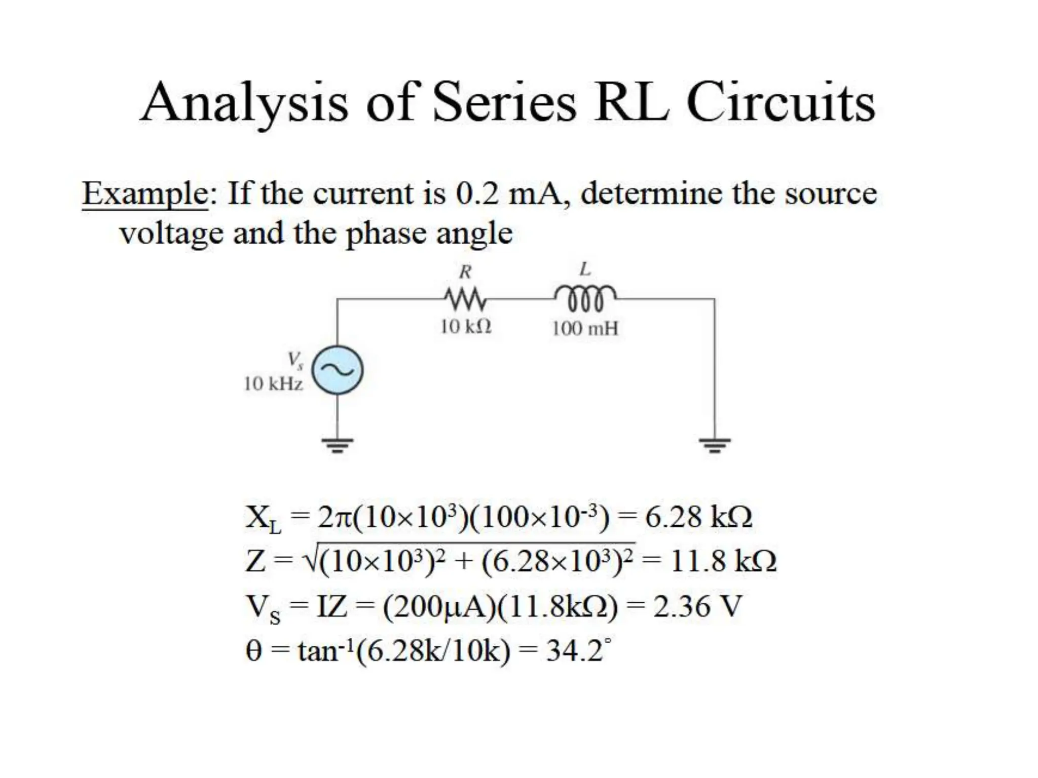
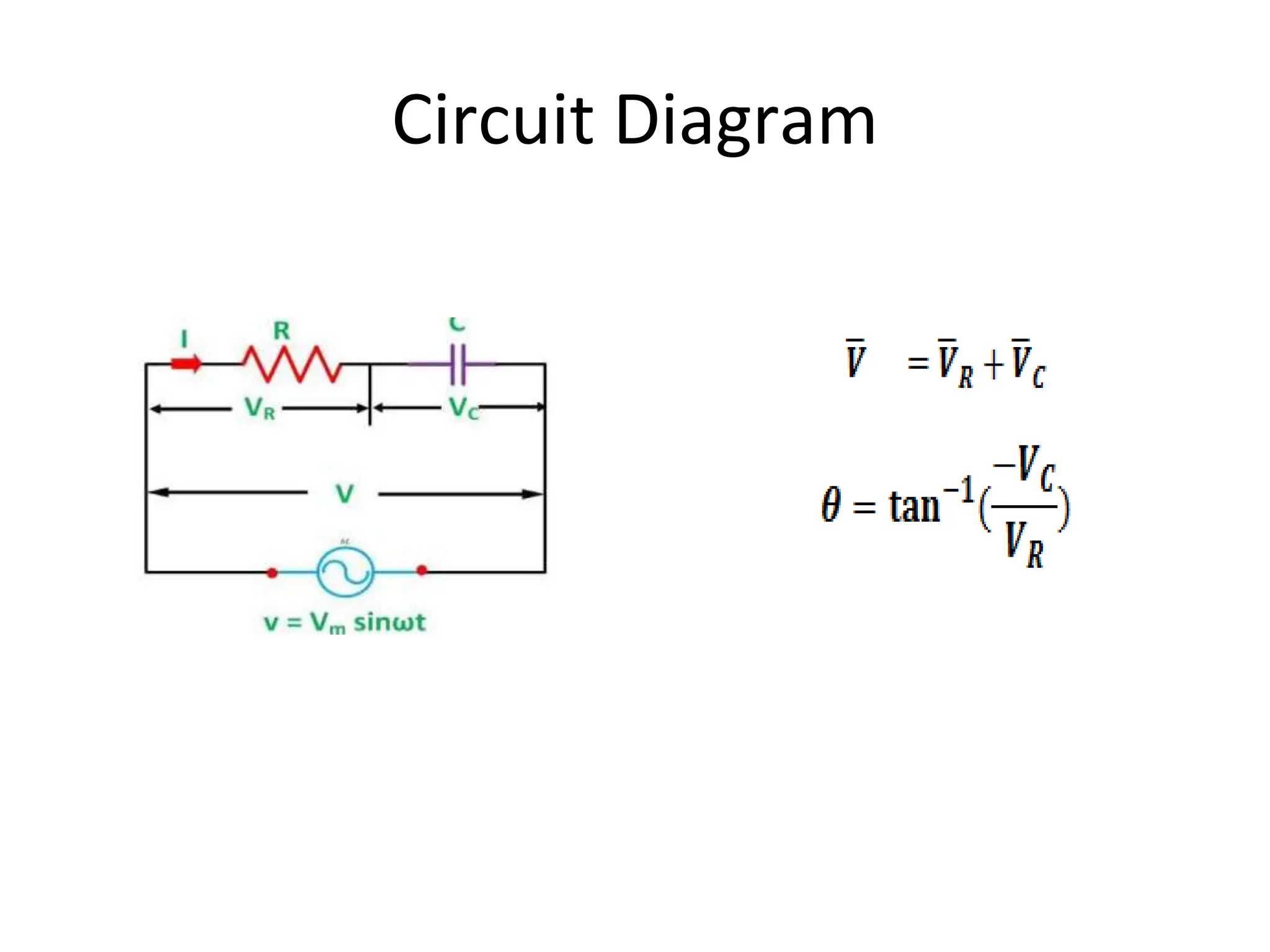
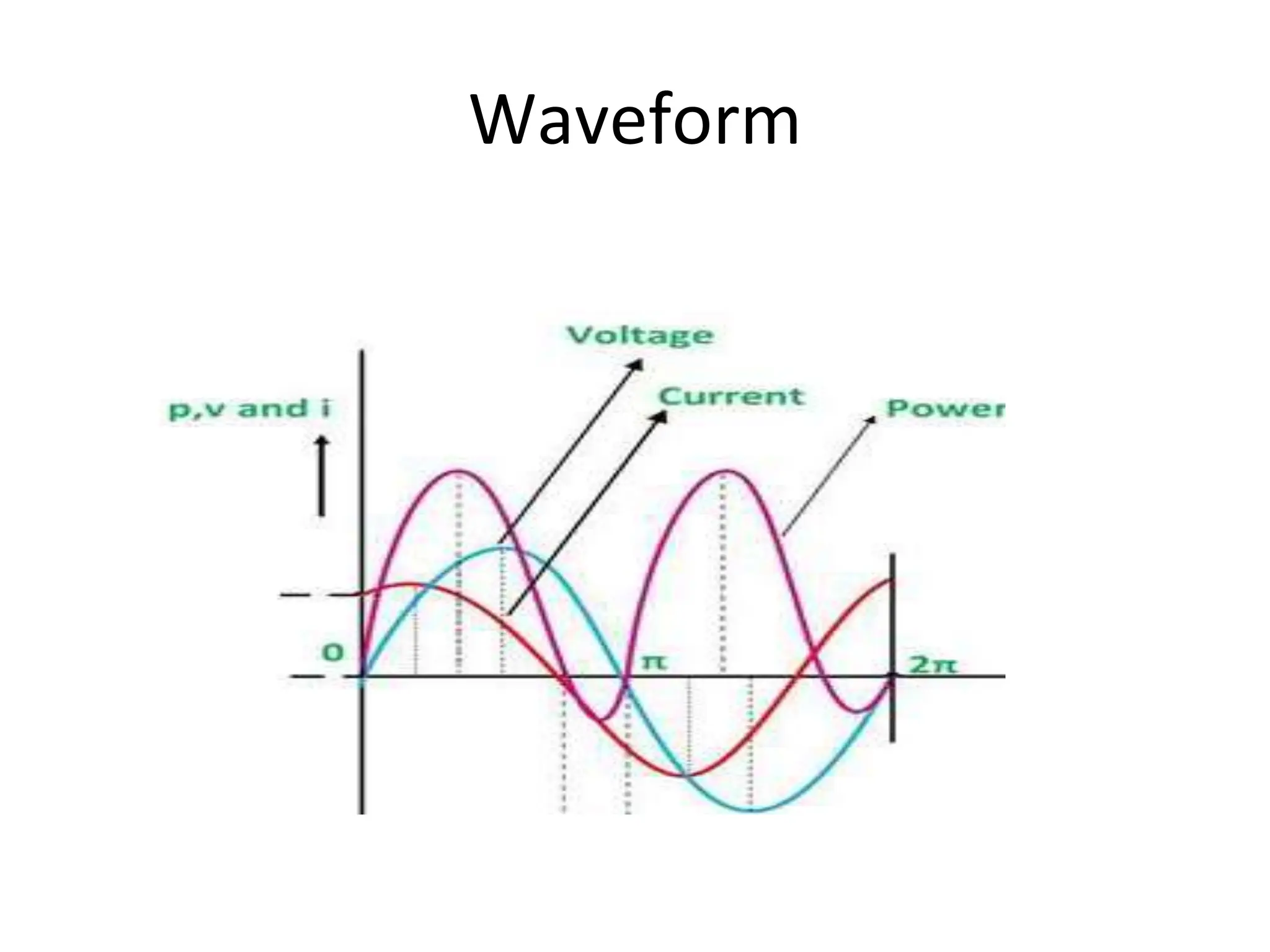
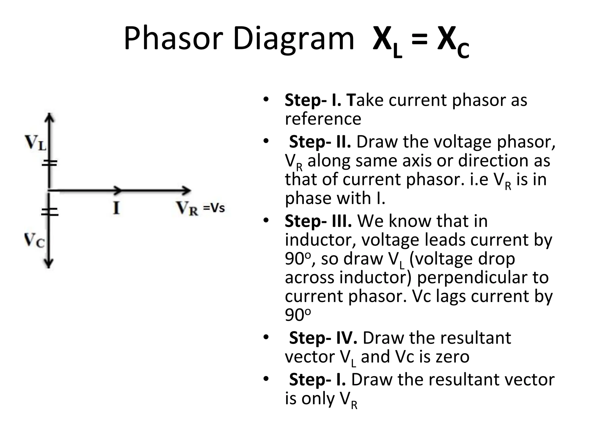
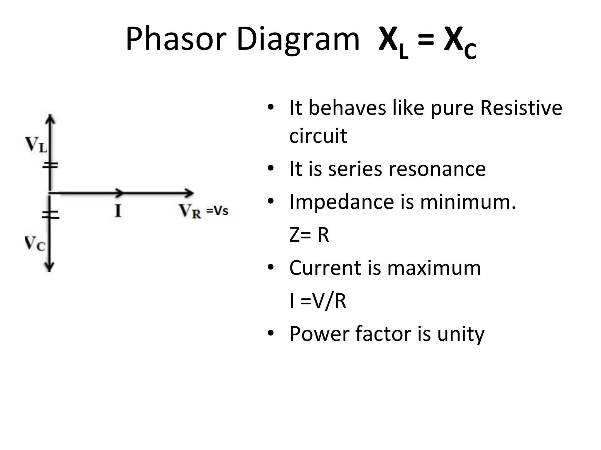
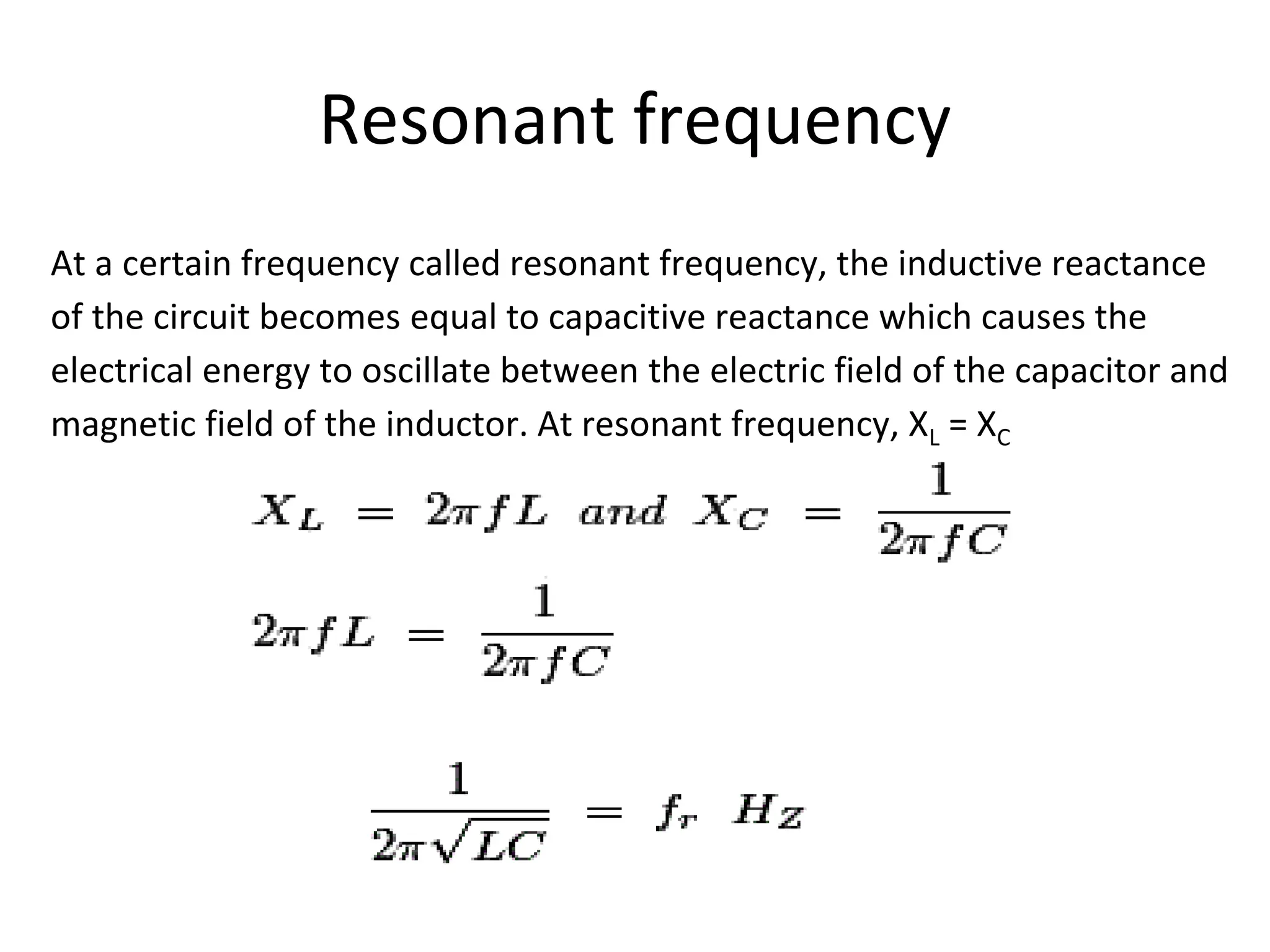
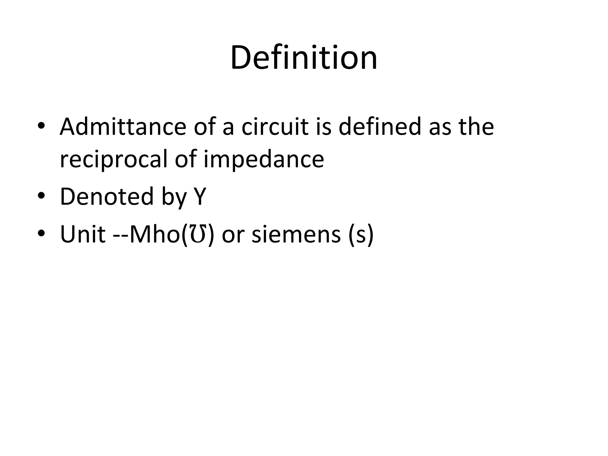
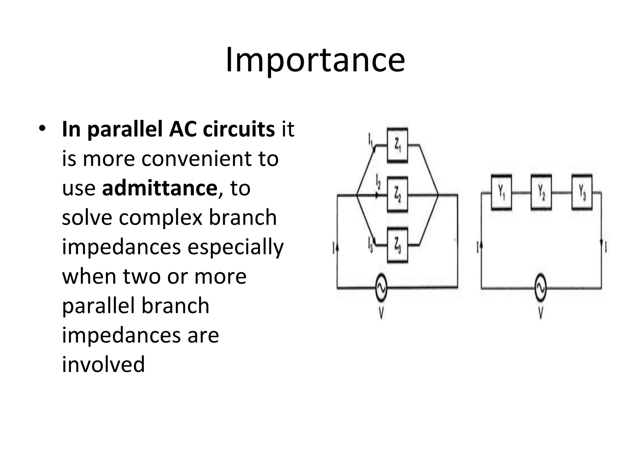
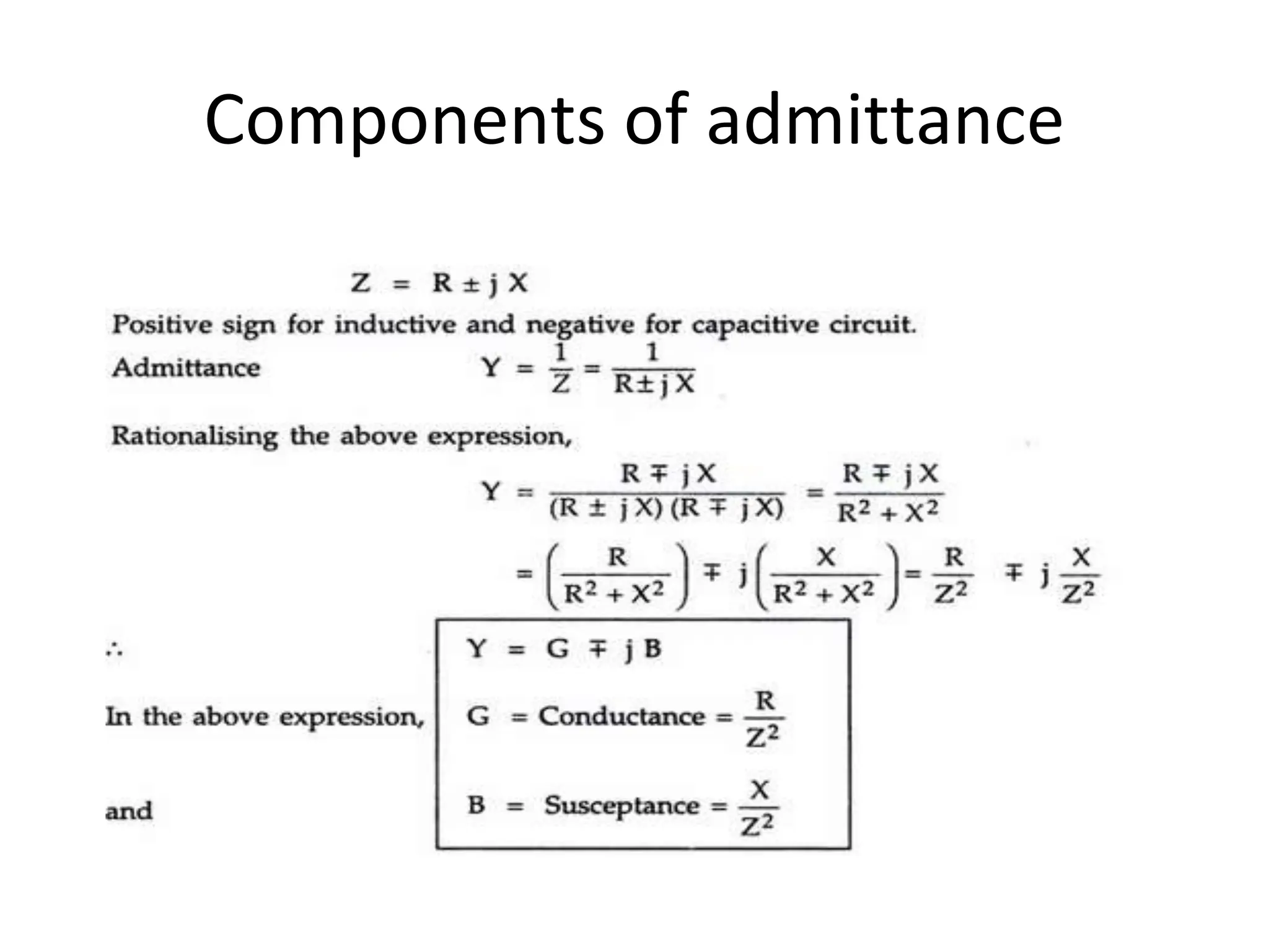
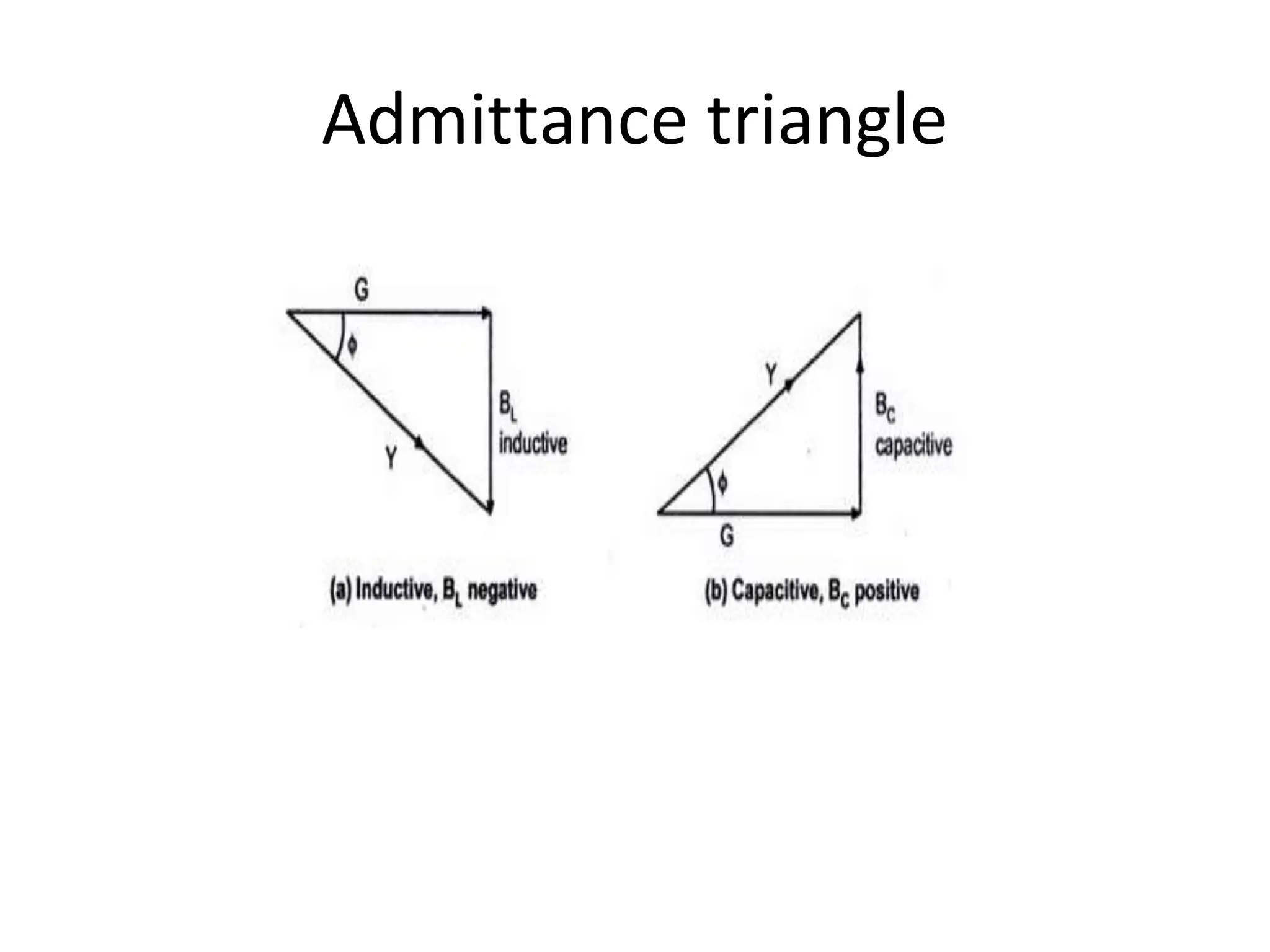
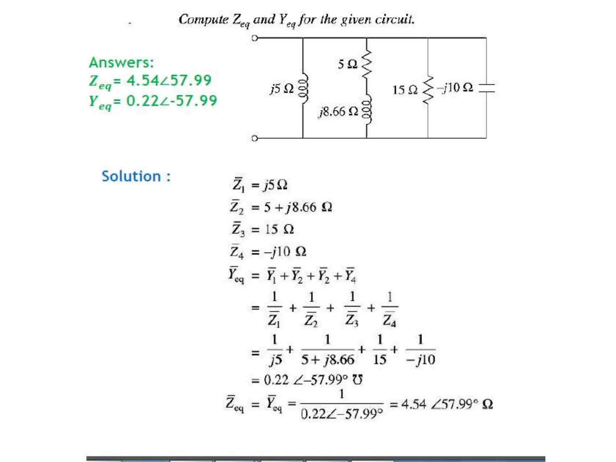
RL Series Circuit
Objectives
• Describe the relationship between current and
voltage in an RL circuit
• Determine impedance and phase angle in a
Series RL circuit
• Analyze a series RL circuit
• Determine power in RL circuits
Circuit Diagram
Let VR and VL be the voltage drop across resistor and inductor
Phasor Diagram
• Step- I. Take current phasor as
reference and draw it on horizontal
axis as shown in diagram.
• Step- II. In case of resistor, both
voltage and current are in same
phase. So draw the voltage phasor,
VR along same axis or direction as
that of current phasor. i.e VR is in
phase with I.
• Step- III. We know that in inductor,
voltage leads current by 90o, so draw
VL (voltage drop across inductor)
perpendicular to current phasor.
• Step- IV. Now we have two voltages
VR and VL. Draw the resultant
vector(V) of these two voltages. Such
as, and from right angle triangle we
get, phase angle
Waveform
• In case of pure resistive
circuit, the phase angle
between voltage and
current is zero and in case
of pure inductive circuit,
phase angle is 90o but
when we combine both
resistance and inductor,
the phase angle of a series
RL circuit is between 0o to
90o.
Impedance Triangle
Power
• Instantaneous power is given by,
Average Power = 𝑃𝐴𝑣𝑔 = ∫𝑃𝑖𝑛𝑠𝑡 =𝑽𝒎𝑰𝒎/𝟐 cosΦ =
(𝑽𝒎/√𝟐)(𝑰𝒎/√𝟐) cosΦ
= 𝑉𝑅𝑀𝑆 𝐼𝑅𝑀𝑆 cosΦ
P = V I cosΦ
Waveform
Summary
• Total current in an RL circuit always lags the
source voltage
• In an RL circuit, the impedance is determined
by both the resistance and the inductive
reactance combined
• The impedance of an RL circuit varies directly
with frequency
RC Series Circuit
Objectives
• Describe the relationship between current and
voltage in an RC circuit
• Determine impedance and phase angle in a
Series RC circuit
• Analyze a series RC circuit
• Determine power in RC circuits
Circuit Diagram
Phasor diagram
• Step- I. Take current phasor as
reference and draw it on horizontal
axis as shown in diagram.
• Step- II. In case of resistor, both
voltage and current are in same
phase. So draw the voltage phasor,
VR along same axis or direction as
that of current phasor. i.e VR is in
phase with I.
• Step- III. We know that Capacitor,
voltage lags current by 90o, so draw
VC (voltage drop across Capacitor)
perpendicular to current phasor.
• Step- IV. Now we have two voltages
VR and VC. Draw the resultant
vector(V) of these two voltages.
Impedance Triangle
Power
PowerTriangle
Waveform
Summary
• Total current in an RC circuit always leads the
source voltage
• In an RC circuit, the impedance is determined
by both the resistance and the Capacitive
reactance combined
RLC Series Circuit
Mrs. M R Yashwante
MMIT Lohgaon
Objectives
• Describe the relationship between current and
voltage in an RLC circuit
• Determine impedance and phase angle in a
Series RLC circuit
• Analyze a series RLC circuit
• Determine power in RLC circuits
Circuit Diagram
Phasor Diagram XL ˃ XC
• Step- I. Take current phasor as
reference
• Step- II. Draw the voltage phasor,
VR along same axis or direction as
that of current phasor. i.e VR is in
phase with I.
• Step- III. We know that in
inductor, voltage leads current by
90o, so draw VL (voltage drop
across inductor) perpendicular to
current phasor. Vc lags current by
90o
• Step- IV. Draw the resultant
vector VL and Vc along VL
• Step- I. Draw the resultant vector
(VL –Vc) & VR
Phasor Diagram XL ˃ XC
• If the inductive reactance is
greater than the capacitive
reactance, i.e XL > XC, then
the RLC circuit has lagging
phase angle
• It behaves like inductive
circuit
Phasor Diagram XL < XC
• if the capacitive reactance is
greater than the inductive
reactance, i.e XC > XL then
the RLC circuit have leading
phase angle
• It behaves like capacitive
circuit
Phasor Diagram XL = XC
• Step- I. Take current phasor as
reference
• Step- II. Draw the voltage phasor,
VR along same axis or direction as
that of current phasor. i.e VR is in
phase with I.
• Step- III. We know that in
inductor, voltage leads current by
90o, so draw VL (voltage drop
across inductor) perpendicular to
current phasor. Vc lags current by
90o
• Step- IV. Draw the resultant
vector VL and Vc is zero
• Step- I. Draw the resultant vector
is only VR
Phasor Diagram XL = XC
• It behaves like pure Resistive
circuit
• It is series resonance
• Impedance is minimum.
Z= R
• Current is maximum
I =V/R
• Power factor is unity
Resonant frequency
At a certain frequency called resonant frequency, the inductive reactance
of the circuit becomes equal to capacitive reactance which causes the
electrical energy to oscillate between the electric field of the capacitor and
magnetic field of the inductor. At resonant frequency, XL = XC
Admittance
Definition
• Admittance of a circuit is defined as the
reciprocal of impedance
• Denoted by Y
• Unit --Mho(℧) or siemens (s)
Importance
• In parallel AC circuits it
is more convenient to
use admittance, to
solve complex branch
impedances especially
when two or more
parallel branch
impedances are
involved
Components of admittance
Admittance triangle
Unit3 AC Series Circuit-RL, RC, RLC.pptx

Unit3 AC Series Circuit-RL, RC, RLC.pptx

  • 1.
  • 2.
    Objectives • Describe therelationship between current and voltage in an RL circuit • Determine impedance and phase angle in a Series RL circuit • Analyze a series RL circuit • Determine power in RL circuits
  • 3.
    Circuit Diagram Let VRand VL be the voltage drop across resistor and inductor
  • 4.
    Phasor Diagram • Step-I. Take current phasor as reference and draw it on horizontal axis as shown in diagram. • Step- II. In case of resistor, both voltage and current are in same phase. So draw the voltage phasor, VR along same axis or direction as that of current phasor. i.e VR is in phase with I. • Step- III. We know that in inductor, voltage leads current by 90o, so draw VL (voltage drop across inductor) perpendicular to current phasor. • Step- IV. Now we have two voltages VR and VL. Draw the resultant vector(V) of these two voltages. Such as, and from right angle triangle we get, phase angle
  • 5.
    Waveform • In caseof pure resistive circuit, the phase angle between voltage and current is zero and in case of pure inductive circuit, phase angle is 90o but when we combine both resistance and inductor, the phase angle of a series RL circuit is between 0o to 90o.
  • 6.
  • 7.
    Power • Instantaneous poweris given by, Average Power = 𝑃𝐴𝑣𝑔 = ∫𝑃𝑖𝑛𝑠𝑡 =𝑽𝒎𝑰𝒎/𝟐 cosΦ = (𝑽𝒎/√𝟐)(𝑰𝒎/√𝟐) cosΦ = 𝑉𝑅𝑀𝑆 𝐼𝑅𝑀𝑆 cosΦ P = V I cosΦ
  • 9.
  • 12.
    Summary • Total currentin an RL circuit always lags the source voltage • In an RL circuit, the impedance is determined by both the resistance and the inductive reactance combined • The impedance of an RL circuit varies directly with frequency
  • 13.
  • 14.
    Objectives • Describe therelationship between current and voltage in an RC circuit • Determine impedance and phase angle in a Series RC circuit • Analyze a series RC circuit • Determine power in RC circuits
  • 15.
  • 16.
    Phasor diagram • Step-I. Take current phasor as reference and draw it on horizontal axis as shown in diagram. • Step- II. In case of resistor, both voltage and current are in same phase. So draw the voltage phasor, VR along same axis or direction as that of current phasor. i.e VR is in phase with I. • Step- III. We know that Capacitor, voltage lags current by 90o, so draw VC (voltage drop across Capacitor) perpendicular to current phasor. • Step- IV. Now we have two voltages VR and VC. Draw the resultant vector(V) of these two voltages.
  • 17.
  • 18.
  • 19.
  • 20.
  • 21.
    Summary • Total currentin an RC circuit always leads the source voltage • In an RC circuit, the impedance is determined by both the resistance and the Capacitive reactance combined
  • 22.
    RLC Series Circuit Mrs.M R Yashwante MMIT Lohgaon
  • 23.
    Objectives • Describe therelationship between current and voltage in an RLC circuit • Determine impedance and phase angle in a Series RLC circuit • Analyze a series RLC circuit • Determine power in RLC circuits
  • 24.
  • 25.
    Phasor Diagram XL˃ XC • Step- I. Take current phasor as reference • Step- II. Draw the voltage phasor, VR along same axis or direction as that of current phasor. i.e VR is in phase with I. • Step- III. We know that in inductor, voltage leads current by 90o, so draw VL (voltage drop across inductor) perpendicular to current phasor. Vc lags current by 90o • Step- IV. Draw the resultant vector VL and Vc along VL • Step- I. Draw the resultant vector (VL –Vc) & VR
  • 26.
    Phasor Diagram XL˃ XC • If the inductive reactance is greater than the capacitive reactance, i.e XL > XC, then the RLC circuit has lagging phase angle • It behaves like inductive circuit
  • 27.
    Phasor Diagram XL< XC • if the capacitive reactance is greater than the inductive reactance, i.e XC > XL then the RLC circuit have leading phase angle • It behaves like capacitive circuit
  • 28.
    Phasor Diagram XL= XC • Step- I. Take current phasor as reference • Step- II. Draw the voltage phasor, VR along same axis or direction as that of current phasor. i.e VR is in phase with I. • Step- III. We know that in inductor, voltage leads current by 90o, so draw VL (voltage drop across inductor) perpendicular to current phasor. Vc lags current by 90o • Step- IV. Draw the resultant vector VL and Vc is zero • Step- I. Draw the resultant vector is only VR
  • 29.
    Phasor Diagram XL= XC • It behaves like pure Resistive circuit • It is series resonance • Impedance is minimum. Z= R • Current is maximum I =V/R • Power factor is unity
  • 30.
    Resonant frequency At acertain frequency called resonant frequency, the inductive reactance of the circuit becomes equal to capacitive reactance which causes the electrical energy to oscillate between the electric field of the capacitor and magnetic field of the inductor. At resonant frequency, XL = XC
  • 31.
  • 32.
    Definition • Admittance ofa circuit is defined as the reciprocal of impedance • Denoted by Y • Unit --Mho(℧) or siemens (s)
  • 33.
    Importance • In parallelAC circuits it is more convenient to use admittance, to solve complex branch impedances especially when two or more parallel branch impedances are involved
  • 34.
  • 35.