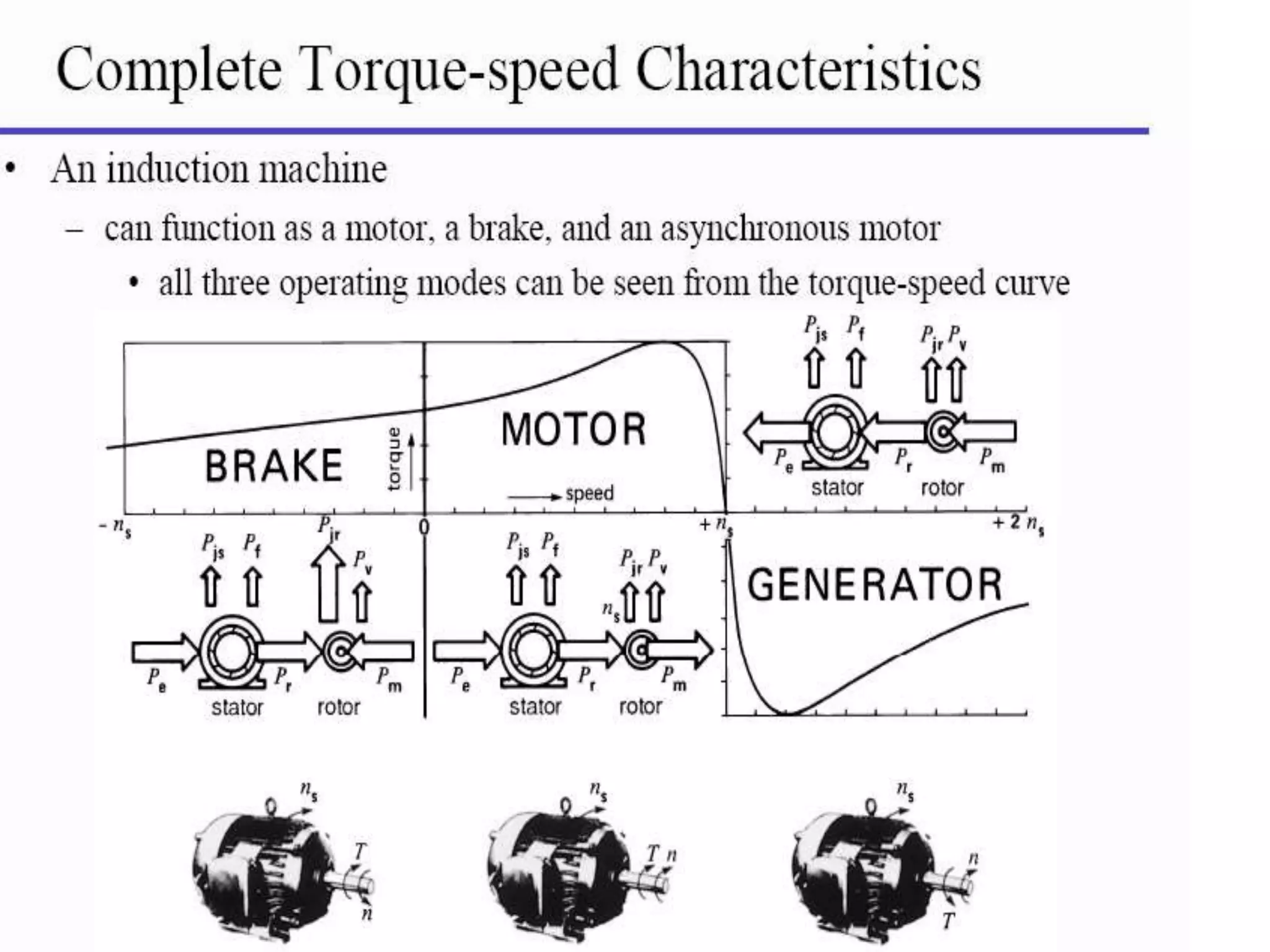
“INDUCTION GENERATOR”
 PREPARED BY :
DISHANT PATEL S. 140123109009
VISHAL GOHEL R. 140123109003
JAY PANCHAL H. 140123109007
GUIDED BY : Prof. Supraja Giddaluru
CONTENTS:
 Induction generator
 Principle of operation induction generator
 Reactive power requirement, voltage built-
up & control.
 Advantages & Disadvantages
 Application
 When the induction motor runs above the synchronous
speed then its runs as a generator called induction generator.
 The negative slip indicate that the rotor of induction motor is
running faster then the synchronous speed.
 Fig. show the induction generator which is driven by the
prime mover such as a wind turbine is connected to a
load.
 When the speed of induction generator above
synchronous speed the active power delivered by the 3-
phase load.
 The corresponding mode of operation of induction
machine is called generating mode & the slip of induction
machine will be negative.
 The construction of induction generator is the same as
that of induction motor.
Principle of operation
 When the 3-phase induction motor is driven at a speed
greater than synchronous speed(-ve slip) by an external
prime mover with exciting current provided either from 3-
phase line or capacitor bank.
 The emf and current of slip frequency will appear in the
rotor winding.
 In generating mode of operation, an external prime
mover drives the rotor above the synchronous speed.
 The stator flux induces currents in the rotor, but since the
opposing rotor flux in now cutting the stator coils & the
motor operates as a generator.
Reactive power requirement, voltage
built-up & control
 The induction generator is not self excited machine,
therefore develop rotating magnetic field.
 The reactive power is also required for the connected
inductive load to improve the power factor on the load.
 The induction generator using the delta connected
capacitor bank for the supply of reactive power is called
self excited or isolated induction generator.
 The reactive power required by the generator and for
the connected inductive load is supplied by the
capacitor bank.
 To achieve a given voltage level in an induction
generator, the capacitor bank must supply the
magnetizing or exciting current corresponding to that
level.
 For a particular value of capacitance, the curve
between the voltage and magnetizing or capacitive
current will be linear.
The fig. indicates that how the voltage is built up different
values of capacitance.
At a point p the reactive power demanded by the generator
is equal to the reactive power supplied by the capacitor bank.
For a lagging power factor load, the voltage collapses very
rapidly.
Advantages :
 Mechanically & electrically simpler than other types of
generator.
 Construction: simple, robust & rugged.
 Relatively cheaper.
 Requires no brushes & commutator.
 easy in maintenance.
 They do not have to be synchronized to the supply lines
as does a synchronous generator.
Disadvantages :
 It is not suitable for separate, isolated operation .
 It consumes rather than supplies magnetizing
KVAR.
 It cannot contribute to the maintenance of
system. voltage levels (this is left entirely to the
synchronous generators or capacitors).
 In general it has a lower efficiency.
Applications :
 Induction generator are often used in wind turbines
and small station due to their ability to produce
useful power at varying rotor speed.
 Particularly suitable for wind generating stations as
in this speed is always a variable factor.
 They are also very useful automatic dynamic
braking such as for braking purpose in case of
railways.
 Induction generator for a fixed wind turbine system.
References :
 A.C. Machines By J. G. Jamanani
 Electrical Technology vol – 2 By B. L. Thareja
induction generator

induction generator

  • 1.
    “INDUCTION GENERATOR”  PREPAREDBY : DISHANT PATEL S. 140123109009 VISHAL GOHEL R. 140123109003 JAY PANCHAL H. 140123109007 GUIDED BY : Prof. Supraja Giddaluru
  • 2.
    CONTENTS:  Induction generator Principle of operation induction generator  Reactive power requirement, voltage built- up & control.  Advantages & Disadvantages  Application
  • 3.
     When theinduction motor runs above the synchronous speed then its runs as a generator called induction generator.  The negative slip indicate that the rotor of induction motor is running faster then the synchronous speed.
  • 4.
     Fig. showthe induction generator which is driven by the prime mover such as a wind turbine is connected to a load.  When the speed of induction generator above synchronous speed the active power delivered by the 3- phase load.  The corresponding mode of operation of induction machine is called generating mode & the slip of induction machine will be negative.  The construction of induction generator is the same as that of induction motor.
  • 6.
    Principle of operation When the 3-phase induction motor is driven at a speed greater than synchronous speed(-ve slip) by an external prime mover with exciting current provided either from 3- phase line or capacitor bank.  The emf and current of slip frequency will appear in the rotor winding.  In generating mode of operation, an external prime mover drives the rotor above the synchronous speed.  The stator flux induces currents in the rotor, but since the opposing rotor flux in now cutting the stator coils & the motor operates as a generator.
  • 7.
    Reactive power requirement,voltage built-up & control  The induction generator is not self excited machine, therefore develop rotating magnetic field.  The reactive power is also required for the connected inductive load to improve the power factor on the load.  The induction generator using the delta connected capacitor bank for the supply of reactive power is called self excited or isolated induction generator.
  • 8.
     The reactivepower required by the generator and for the connected inductive load is supplied by the capacitor bank.  To achieve a given voltage level in an induction generator, the capacitor bank must supply the magnetizing or exciting current corresponding to that level.  For a particular value of capacitance, the curve between the voltage and magnetizing or capacitive current will be linear.
  • 9.
    The fig. indicatesthat how the voltage is built up different values of capacitance. At a point p the reactive power demanded by the generator is equal to the reactive power supplied by the capacitor bank. For a lagging power factor load, the voltage collapses very rapidly.
  • 10.
    Advantages :  Mechanically& electrically simpler than other types of generator.  Construction: simple, robust & rugged.  Relatively cheaper.  Requires no brushes & commutator.  easy in maintenance.  They do not have to be synchronized to the supply lines as does a synchronous generator.
  • 11.
    Disadvantages :  Itis not suitable for separate, isolated operation .  It consumes rather than supplies magnetizing KVAR.  It cannot contribute to the maintenance of system. voltage levels (this is left entirely to the synchronous generators or capacitors).  In general it has a lower efficiency.
  • 12.
    Applications :  Inductiongenerator are often used in wind turbines and small station due to their ability to produce useful power at varying rotor speed.  Particularly suitable for wind generating stations as in this speed is always a variable factor.  They are also very useful automatic dynamic braking such as for braking purpose in case of railways.  Induction generator for a fixed wind turbine system.
  • 13.
    References :  A.C.Machines By J. G. Jamanani  Electrical Technology vol – 2 By B. L. Thareja