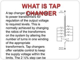
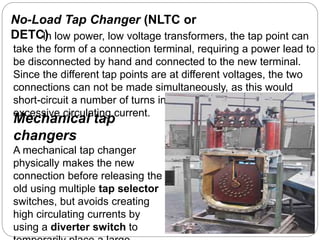
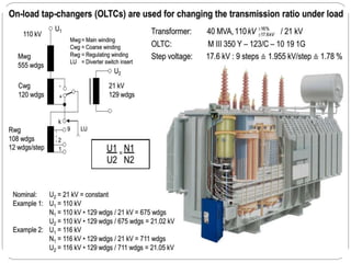
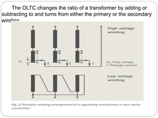
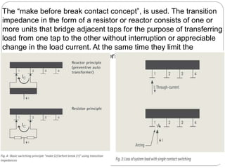
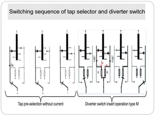
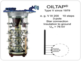
SlideShare a Scribd company logo
A tap changer is a device fitted
to power transformers for
regulation of the output voltage
to required levels. This is
normally achieved by changing
the ratios of the transformers
on the system by altering the
number of turns in one winding
of the appropriate
transformer/s. Tap changers
offer variable control to keep
the supply voltage within the
limits. The 2 ½% step can be
Voltage regulation is normally achieved by changing
the ratios of the transformers on the system by altering
the number of turns in one winding of the appropriate
transformer/s. Tap changers offer variable control to
keep the supply voltage within these limits. Tap
changers can be on load or off load. On load tap
changers generally consist of a diverter switch and a
selector switch operating as a unit to effect transfer
current from one voltage tap to the next. Tap changers
can be adjusted to fit the application needs.
 To supply a desired voltage to the load.
 To counter the voltage drops due to loads.
 To counter the input supply voltage changes on load.
 Additionally required to perform the task of regulation of
active and reactive power flows.
 Some form of impedance is present to
prevent short circuiting of the tapped
section.
 A duplicate circuit is provided so that
the
load current can be carried by one circuit
whilst switching is being carried out on the
other.
 Nominal Voltage set point.
 Bandwidth (the amount of variation allowed before a
tap change
occurs).
 Time delay (The amount of time the voltage must be
outside the
bandwidth before a tap change occurs) .
 Line drop compensation ( a way vary the set point
voltage to
compensate for heavy loads)
Tap point is placed
 In star connected winding, near the star point.
 In delta connected winding, at the center of the windin
 In autotransformer, between the series and common
Tap changers connected to the primary or
secondary side windings of the transformer
depending on:
 Current rating of the transformer.
 Insulation levels present.
 Type of winding within the transformer (eg. Star, delta or
autotransformer).
 Position of tap changer in the winding.
 Losses associated with different tap changer configurations eg.
Coarse tap or
reverse winding.
 Step voltage and circulating currents.
 Cost.
 Physical size.
No-Load Tap Changer (NLTC or
DETC)
On Load Tap Changer (OLTC
 Mechanical tap changers
 Thyristor-assisted tap changers
 Solid state (thyristor) tap
changers
No-Load Tap Changer (NLTC or
DETC)In low power, low voltage transformers, the tap point can
take the form of a connection terminal, requiring a power lead to
be disconnected by hand and connected to the new terminal.
Since the different tap points are at different voltages, the two
connections can not be made simultaneously, as this would
short-circuit a number of turns in the winding and produce
excessive circulating current.
Mechanical tap
changers
A mechanical tap changer
physically makes the new
connection before releasing the
old using multiple tap selector
switches, but avoids creating
high circulating currents by
using a diverter switch to
Solid state (thyristor) tap changer
Recently developed which uses thyristors both to
switch the load current and to pass the load current in the
steady state. Their disadvantage is that all of the non-
conducting thyristors connected to the unselected taps still
dissipate power due to their leakage current.
Thyristor-assisted tap changers
Thyristor-assisted tap changers use thyristors to
take the on-load current while the main contacts change
over from one tap to the previous. This prevents arcing on
the main contacts and can lead to a longer service life.
On Load Tap Changer (OLTC)
OLTCs enable voltage regulation and/or phase shifting by
varying the transformer ratio under load without interruption. On
load tap changers generally consist of a diverter switch and a
selector switch operating as a unit to effect transfer current from
one voltage tap to the next. The selector selects the taps and is
operating in the transformer oil. The diverter is the actual switch
with high current contacts that balances the load from one tap to
the other. The divertor is inside a separate compartment inside the
transformer tank. The diverter and selector are positionned above
each-other and driven by the same axe. The voltage between the
taps is known as the step voltage, which normally lies between
0.8 % and 2.5 % of the rated voltage of the transformer.
Two switching principles have been used for load
transfer
operation :
1.the high-speed resistor-type OLTCs
2.the reactor-type OLTCs.
The resistor-type OLTCs are installed inside the transformer
tank (in-tank OLTCs)
The reactor-type OLTCs are in a separate compartment which
is normally welded to the transformer tank
The OLTC changes the ratio of a transformer by adding or
subtracting to and turns from either the primary or the secondary
winding.
The “make before break contact concept”, is used. The transition
impedance in the form of a resistor or reactor consists of one or
more units that bridge adjacent taps for the purpose of transferring
load from one tap to the other without interruption or appreciable
change in the load current. At the same time they limit the
circulating current (IC ) for the period when both taps are used.
Examples of commonly used winding
schemes
In star/wye connection, windings have
regulation applied to the neutral end.
Regulation of delta-connected windings requires a three-
phase OLTC whose three phases are insulated according
to the highest system voltage applied.
Today, the design limit for three-phase OLTCs with phase-
to-phase insulation is the highest voltage for equipment of
145 kV.
To reduce the phase-to-phase stresses on the delta-
OLTC the three pole mid-winding arrangement (fig. 7 c)
can be used.
For regulated autotransformers, the most appropriate
scheme is chosen with
regard to regulating range, system conditions and/or
requirements, as well as weight and size restrictions during
transportation. Autotransformers are always wye-connected.
The switching capacity itself is primarily a function of the
contact design, contact speed and arc-quenching agent.
Based on that OLTC are of two type:
1. Oil-type OLTCs
2. Vacuum-type OLTCs
Resistor oil-type OLTCs
In an oil-type OLTC, the OLTC is immersed in
transformer oil and switching contacts make and break
current under oil.
For higher ratings and higher voltages comprises a
diverter switch (arcing switch) and a tap selector.
For lower ratings, OLTC designs in which the functions of
the diverter switch (arcing switch) and the tap selector are
1. With a diverter switch & a tap selector operation takes place in t
a. The next is preselected by the tap selector at no load.
b. The diverter switch then transfers the load current from the tap
operation to the preselected tap.
 The OLTC is operated by means of a drive mechanism.
 Switching time of a divertor switch is b/w 40 &60 ms.
 Transition resistor are inserted which are loaded for 20-30 ms.
 Total operation time 3-1o sec.
2. A selector switch(arcing tap switch) carries out the tap in one ste
tap in service to the adjacent tap
Reactor oil-type OLTCs
The following types of switching are used for reactor oil-
type OLTCs:
1. Selector switch (arcing tap switch)
2. Diverter switch (arcing switch) with tap selector
Technical features
 The vacuum interrupter is a hermetically-sealed system.
 There is no interaction with the surrounding medium, despite the arc.
 The switching characteristics do not depend on the surrounding medium.
 Low energy consumption.
 Reduced contact wear.
 Elimination of the insulating medium as the arc quenching agent.
 Elimination of by-products e. g. carbon when using transformer oil.
 On-line filter is unnecessary.
 Easy disposal.
 No aging of the quenching medium.
 Constant or even improving switching characteristics throughout the entire
lifespan of the
vacuum interrupters (getter effect).
 No interaction/oxidation during switching.
 High rate of recondensation of metal vapour on contacts extends contact
life.
 Constantly low contact resistance.
 Extraordinary fast dielectric recovery of up to 10 kV/µs.
 Ensures short arcing times (maximum one halfcycle) even in the case of
To select the appropriate OLTC, the following key data
of the corresponding transformer windings should be
known:
 MVA rating.
 Connection of tap winding (for wye, delta or singlephase
connection).
 Rated voltage and regulating range.
 Number of service tap positions.
 Insulation level to ground.
 Lightning impulse and power frequency voltage of internal
insulation.
The following OLTC operating data may be derived
from this information:
 Rated through-current: Iu
The appropriate tap-changer can be
determined:
 OLTC type
 Number of poles
 Nominal voltage level of OLTC
 Tap selector size/insulation level
 Basic connection diagram
During the operation of the diverter switch (arcing switch)
from the end of the tap winding to the end of the coarse
winding and vice versa, all turns of the whole tap winding and
coarse winding are inserted in the circuit.
This results in a leakage impedance value which is
substantially higher than during operation within the tap
winding where only negligible leakage impedance of one step
is relevant. The higher impedance value in series with the
transition resistors has an effect on the circulating current
which is flowing in the opposite direction through coarse
winding and tap winding during diverter switch operation.
Consequently a phase shift between switched current and
recovery voltage takes place at the transition contacts of the
diverter switch and may result in an extended arcing time.
In order to ensure optimal selection, it is necessary to
 Reduction of power losses
 Voltage profile enhancement
 Voltage stability
The tap changing transformer is connected at the load terminal, its
tap ratio is ‘t’. Transformer reactance at unity off-nominal tap ratio
The approximate voltage drop formula is
System voltages and impedance referred to the system load side a
respectively
Voltage value of sec. terminal of transformer can be
regulated using tap changer. This regulation also affects
the calculation of the thevenin equivalent parameters.
Changes of equivalent parameters cause a change of
voltage stability conditions.
In the radial distribution system, each radial feeder is
divided into load sections with a tap changing transformer at
the beginning of the distribution network. However, there is the
need to find the tap setting of the substation transformer that
would give minimum distribution loss while satisfying the
operating constraints under a certain load pattern. These
operating constraints are voltage drop, current capacity and
radial operating structure of the system. The mathematical
formulation for the minimization of power loss tap changer
problems is
Tap changer

More Related Content

What's hot

33/11 KV SUBSTATION
33/11 KV SUBSTATION33/11 KV SUBSTATION
33/11 KV SUBSTATION
k,l polytechnic roorkee
 
Testing,maintenance&protection
Testing,maintenance&protectionTesting,maintenance&protection
Testing,maintenance&protection
Rakesh Joshi
 
Transformer basic
Transformer basicTransformer basic
Transformer basic
BHAGWAN PRASAD
 
Switch yard & Protection
Switch yard & ProtectionSwitch yard & Protection
Switch yard & Protection
MANOJ KUMAR MAHARANA
 
Presentation on 132/33 KVSubstation Training
Presentation on 132/33 KVSubstation Training Presentation on 132/33 KVSubstation Training
Presentation on 132/33 KVSubstation Training
Sakshi Rastogi
 
Transformer protection
Transformer protectionTransformer protection
Transformer protection
jawaharramaya
 
33kv substation
33kv substation33kv substation
33kv substation
Abhishek Dawachya
 
Power Transformer in DPL
Power Transformer in DPLPower Transformer in DPL
Power Transformer in DPL
Abhishek Roy
 
HIGH VOL TAGE TESTING OF TRANSFORMER BY HARI SHANKAR SINGH
HIGH VOL TAGE TESTING OF TRANSFORMER BY HARI SHANKAR SINGHHIGH VOL TAGE TESTING OF TRANSFORMER BY HARI SHANKAR SINGH
HIGH VOL TAGE TESTING OF TRANSFORMER BY HARI SHANKAR SINGHShankar Singh
 
Substation protection devices
Substation protection devicesSubstation protection devices
Substation protection devices
Rahul Aman
 
Protective relay
Protective relay Protective relay
Protective relay
Uday Wankar
 
Unit 03 Protective relays
Unit  03 Protective relaysUnit  03 Protective relays
Unit 03 Protective relays
PremanandDesai
 
PRESENTATION ON MANUFACTURING OF TRANSFORMER By Dhruv Jimit
PRESENTATION ON MANUFACTURING OF TRANSFORMER By Dhruv JimitPRESENTATION ON MANUFACTURING OF TRANSFORMER By Dhruv Jimit
PRESENTATION ON MANUFACTURING OF TRANSFORMER By Dhruv Jimit
Jimit Dhruv
 
Transformer Designing
Transformer Designing Transformer Designing
Transformer Designing
Praveen Sharma
 
Transformers protection, an introduction
Transformers protection, an introductionTransformers protection, an introduction
Transformers protection, an introduction
H. Kheir
 
Ppt on protection of power transformers
Ppt on protection of power transformersPpt on protection of power transformers
Ppt on protection of power transformers
siddharam kantoli
 
GENERATING OF HIGH ALTERNATING VOLTAGE
GENERATING OF HIGH ALTERNATING VOLTAGEGENERATING OF HIGH ALTERNATING VOLTAGE
GENERATING OF HIGH ALTERNATING VOLTAGE
Jamil Abdullah
 
Presentation on Power transformer
Presentation on Power transformerPresentation on Power transformer
Presentation on Power transformer
Sudarshan Pandey
 
Switchyard design overview
Switchyard design overviewSwitchyard design overview
Switchyard design overview
Milind Punj
 

What's hot (20)

33/11 KV SUBSTATION
33/11 KV SUBSTATION33/11 KV SUBSTATION
33/11 KV SUBSTATION
 
Testing,maintenance&protection
Testing,maintenance&protectionTesting,maintenance&protection
Testing,maintenance&protection
 
Transformer basic
Transformer basicTransformer basic
Transformer basic
 
Switch yard & Protection
Switch yard & ProtectionSwitch yard & Protection
Switch yard & Protection
 
Presentation on 132/33 KVSubstation Training
Presentation on 132/33 KVSubstation Training Presentation on 132/33 KVSubstation Training
Presentation on 132/33 KVSubstation Training
 
Transformer protection
Transformer protectionTransformer protection
Transformer protection
 
33kv substation
33kv substation33kv substation
33kv substation
 
Protection and Switchgear
Protection and SwitchgearProtection and Switchgear
Protection and Switchgear
 
Power Transformer in DPL
Power Transformer in DPLPower Transformer in DPL
Power Transformer in DPL
 
HIGH VOL TAGE TESTING OF TRANSFORMER BY HARI SHANKAR SINGH
HIGH VOL TAGE TESTING OF TRANSFORMER BY HARI SHANKAR SINGHHIGH VOL TAGE TESTING OF TRANSFORMER BY HARI SHANKAR SINGH
HIGH VOL TAGE TESTING OF TRANSFORMER BY HARI SHANKAR SINGH
 
Substation protection devices
Substation protection devicesSubstation protection devices
Substation protection devices
 
Protective relay
Protective relay Protective relay
Protective relay
 
Unit 03 Protective relays
Unit  03 Protective relaysUnit  03 Protective relays
Unit 03 Protective relays
 
PRESENTATION ON MANUFACTURING OF TRANSFORMER By Dhruv Jimit
PRESENTATION ON MANUFACTURING OF TRANSFORMER By Dhruv JimitPRESENTATION ON MANUFACTURING OF TRANSFORMER By Dhruv Jimit
PRESENTATION ON MANUFACTURING OF TRANSFORMER By Dhruv Jimit
 
Transformer Designing
Transformer Designing Transformer Designing
Transformer Designing
 
Transformers protection, an introduction
Transformers protection, an introductionTransformers protection, an introduction
Transformers protection, an introduction
 
Ppt on protection of power transformers
Ppt on protection of power transformersPpt on protection of power transformers
Ppt on protection of power transformers
 
GENERATING OF HIGH ALTERNATING VOLTAGE
GENERATING OF HIGH ALTERNATING VOLTAGEGENERATING OF HIGH ALTERNATING VOLTAGE
GENERATING OF HIGH ALTERNATING VOLTAGE
 
Presentation on Power transformer
Presentation on Power transformerPresentation on Power transformer
Presentation on Power transformer
 
Switchyard design overview
Switchyard design overviewSwitchyard design overview
Switchyard design overview
 

Similar to Tap changer

A320108
A320108A320108
PED drivers t5656979089897877ghvvnvgcxxn
PED drivers t5656979089897877ghvvnvgcxxnPED drivers t5656979089897877ghvvnvgcxxn
PED drivers t5656979089897877ghvvnvgcxxn
nightbot15
 
Dc chopper and switching ps vr
Dc chopper and switching ps vrDc chopper and switching ps vr
Dc chopper and switching ps vr
edwin deveza
 
Comparative Application of Load Tap-Changing Transformer (LTCT) and Shunt Cap...
Comparative Application of Load Tap-Changing Transformer (LTCT) and Shunt Cap...Comparative Application of Load Tap-Changing Transformer (LTCT) and Shunt Cap...
Comparative Application of Load Tap-Changing Transformer (LTCT) and Shunt Cap...
International journal of scientific and technical research in engineering (IJSTRE)
 
ECE 505 Power electronics final paper
ECE 505 Power electronics final paperECE 505 Power electronics final paper
ECE 505 Power electronics final paperRob Garrone
 
Overview of custom power devices
Overview of custom power devicesOverview of custom power devices
Overview of custom power devices
Raja Adapa
 
Measurement of motion, force and torque
Measurement of motion, force and torqueMeasurement of motion, force and torque
Measurement of motion, force and torque
ARKA JAIN University
 
Review of Step down Converter with Efficient ZVS Operation
Review of Step down Converter with Efficient ZVS OperationReview of Step down Converter with Efficient ZVS Operation
Review of Step down Converter with Efficient ZVS Operation
IJRST Journal
 
Autotransformer electrical
Autotransformer  electricalAutotransformer  electrical
Autotransformer electrical
Souvik Dutta
 
2 twofold mode series echoing dc dc converter for ample load
2 twofold mode series echoing dc dc converter for ample load2 twofold mode series echoing dc dc converter for ample load
2 twofold mode series echoing dc dc converter for ample loadchelliah paramasivan
 
Chokeless welding transformer with load series motor
Chokeless welding transformer with load series motorChokeless welding transformer with load series motor
Chokeless welding transformer with load series motor
eSAT Journals
 
12 16134 paper 064 ijeecs(edit)
12 16134 paper 064 ijeecs(edit)12 16134 paper 064 ijeecs(edit)
12 16134 paper 064 ijeecs(edit)
IAESIJEECS
 
Distribution Transformer Protection for Differential and Overcurrent Faults
Distribution Transformer Protection for Differential and Overcurrent FaultsDistribution Transformer Protection for Differential and Overcurrent Faults
Distribution Transformer Protection for Differential and Overcurrent Faults
ToshaliMohapatra
 
Industrial Training in 2×3.14MVA 33/11 KV substation.
Industrial Training in 2×3.14MVA 33/11 KV substation.Industrial Training in 2×3.14MVA 33/11 KV substation.
Industrial Training in 2×3.14MVA 33/11 KV substation.
rohitkashiv2020
 
Power Corporation ppt
Power Corporation pptPower Corporation ppt
Power Corporation ppt
Kamal Tiwari
 
Sub station training
Sub station trainingSub station training
Sub station training
Durga Prasad, IES
 

Similar to Tap changer (20)

A320108
A320108A320108
A320108
 
PED drivers t5656979089897877ghvvnvgcxxn
PED drivers t5656979089897877ghvvnvgcxxnPED drivers t5656979089897877ghvvnvgcxxn
PED drivers t5656979089897877ghvvnvgcxxn
 
Dc chopper and switching ps vr
Dc chopper and switching ps vrDc chopper and switching ps vr
Dc chopper and switching ps vr
 
Comparative Application of Load Tap-Changing Transformer (LTCT) and Shunt Cap...
Comparative Application of Load Tap-Changing Transformer (LTCT) and Shunt Cap...Comparative Application of Load Tap-Changing Transformer (LTCT) and Shunt Cap...
Comparative Application of Load Tap-Changing Transformer (LTCT) and Shunt Cap...
 
ECE 505 Power electronics final paper
ECE 505 Power electronics final paperECE 505 Power electronics final paper
ECE 505 Power electronics final paper
 
Overview of custom power devices
Overview of custom power devicesOverview of custom power devices
Overview of custom power devices
 
Measurement of motion, force and torque
Measurement of motion, force and torqueMeasurement of motion, force and torque
Measurement of motion, force and torque
 
Review of Step down Converter with Efficient ZVS Operation
Review of Step down Converter with Efficient ZVS OperationReview of Step down Converter with Efficient ZVS Operation
Review of Step down Converter with Efficient ZVS Operation
 
Autotransformer electrical
Autotransformer  electricalAutotransformer  electrical
Autotransformer electrical
 
T&D_Unit V.pdf
T&D_Unit V.pdfT&D_Unit V.pdf
T&D_Unit V.pdf
 
2 twofold mode series echoing dc dc converter for ample load
2 twofold mode series echoing dc dc converter for ample load2 twofold mode series echoing dc dc converter for ample load
2 twofold mode series echoing dc dc converter for ample load
 
Chokeless welding transformer with load series motor
Chokeless welding transformer with load series motorChokeless welding transformer with load series motor
Chokeless welding transformer with load series motor
 
unit_2.ppt
unit_2.pptunit_2.ppt
unit_2.ppt
 
12 16134 paper 064 ijeecs(edit)
12 16134 paper 064 ijeecs(edit)12 16134 paper 064 ijeecs(edit)
12 16134 paper 064 ijeecs(edit)
 
Distribution Transformer Protection for Differential and Overcurrent Faults
Distribution Transformer Protection for Differential and Overcurrent FaultsDistribution Transformer Protection for Differential and Overcurrent Faults
Distribution Transformer Protection for Differential and Overcurrent Faults
 
Industrial Training in 2×3.14MVA 33/11 KV substation.
Industrial Training in 2×3.14MVA 33/11 KV substation.Industrial Training in 2×3.14MVA 33/11 KV substation.
Industrial Training in 2×3.14MVA 33/11 KV substation.
 
Power Corporation ppt
Power Corporation pptPower Corporation ppt
Power Corporation ppt
 
Sub station training
Sub station trainingSub station training
Sub station training
 
unit_2.ppt
unit_2.pptunit_2.ppt
unit_2.ppt
 
RESEARCH EXPLORER -2 ISSUE
RESEARCH EXPLORER -2 ISSUERESEARCH EXPLORER -2 ISSUE
RESEARCH EXPLORER -2 ISSUE
 

Recently uploaded

Hybrid optimization of pumped hydro system and solar- Engr. Abdul-Azeez.pdf
Hybrid optimization of pumped hydro system and solar- Engr. Abdul-Azeez.pdfHybrid optimization of pumped hydro system and solar- Engr. Abdul-Azeez.pdf
Hybrid optimization of pumped hydro system and solar- Engr. Abdul-Azeez.pdf
fxintegritypublishin
 
Planning Of Procurement o different goods and services
Planning Of Procurement o different goods and servicesPlanning Of Procurement o different goods and services
Planning Of Procurement o different goods and services
JoytuBarua2
 
WATER CRISIS and its solutions-pptx 1234
WATER CRISIS and its solutions-pptx 1234WATER CRISIS and its solutions-pptx 1234
WATER CRISIS and its solutions-pptx 1234
AafreenAbuthahir2
 
addressing modes in computer architecture
addressing modes  in computer architectureaddressing modes  in computer architecture
addressing modes in computer architecture
ShahidSultan24
 
CME397 Surface Engineering- Professional Elective
CME397 Surface Engineering- Professional ElectiveCME397 Surface Engineering- Professional Elective
CME397 Surface Engineering- Professional Elective
karthi keyan
 
Automobile Management System Project Report.pdf
Automobile Management System Project Report.pdfAutomobile Management System Project Report.pdf
Automobile Management System Project Report.pdf
Kamal Acharya
 
COLLEGE BUS MANAGEMENT SYSTEM PROJECT REPORT.pdf
COLLEGE BUS MANAGEMENT SYSTEM PROJECT REPORT.pdfCOLLEGE BUS MANAGEMENT SYSTEM PROJECT REPORT.pdf
COLLEGE BUS MANAGEMENT SYSTEM PROJECT REPORT.pdf
Kamal Acharya
 
The Benefits and Techniques of Trenchless Pipe Repair.pdf
The Benefits and Techniques of Trenchless Pipe Repair.pdfThe Benefits and Techniques of Trenchless Pipe Repair.pdf
The Benefits and Techniques of Trenchless Pipe Repair.pdf
Pipe Restoration Solutions
 
ethical hacking in wireless-hacking1.ppt
ethical hacking in wireless-hacking1.pptethical hacking in wireless-hacking1.ppt
ethical hacking in wireless-hacking1.ppt
Jayaprasanna4
 
H.Seo, ICLR 2024, MLILAB, KAIST AI.pdf
H.Seo,  ICLR 2024, MLILAB,  KAIST AI.pdfH.Seo,  ICLR 2024, MLILAB,  KAIST AI.pdf
H.Seo, ICLR 2024, MLILAB, KAIST AI.pdf
MLILAB
 
Quality defects in TMT Bars, Possible causes and Potential Solutions.
Quality defects in TMT Bars, Possible causes and Potential Solutions.Quality defects in TMT Bars, Possible causes and Potential Solutions.
Quality defects in TMT Bars, Possible causes and Potential Solutions.
PrashantGoswami42
 
Nuclear Power Economics and Structuring 2024
Nuclear Power Economics and Structuring 2024Nuclear Power Economics and Structuring 2024
Nuclear Power Economics and Structuring 2024
Massimo Talia
 
Event Management System Vb Net Project Report.pdf
Event Management System Vb Net  Project Report.pdfEvent Management System Vb Net  Project Report.pdf
Event Management System Vb Net Project Report.pdf
Kamal Acharya
 
Pile Foundation by Venkatesh Taduvai (Sub Geotechnical Engineering II)-conver...
Pile Foundation by Venkatesh Taduvai (Sub Geotechnical Engineering II)-conver...Pile Foundation by Venkatesh Taduvai (Sub Geotechnical Engineering II)-conver...
Pile Foundation by Venkatesh Taduvai (Sub Geotechnical Engineering II)-conver...
AJAYKUMARPUND1
 
Vaccine management system project report documentation..pdf
Vaccine management system project report documentation..pdfVaccine management system project report documentation..pdf
Vaccine management system project report documentation..pdf
Kamal Acharya
 
Industrial Training at Shahjalal Fertilizer Company Limited (SFCL)
Industrial Training at Shahjalal Fertilizer Company Limited (SFCL)Industrial Training at Shahjalal Fertilizer Company Limited (SFCL)
Industrial Training at Shahjalal Fertilizer Company Limited (SFCL)
MdTanvirMahtab2
 
Sachpazis:Terzaghi Bearing Capacity Estimation in simple terms with Calculati...
Sachpazis:Terzaghi Bearing Capacity Estimation in simple terms with Calculati...Sachpazis:Terzaghi Bearing Capacity Estimation in simple terms with Calculati...
Sachpazis:Terzaghi Bearing Capacity Estimation in simple terms with Calculati...
Dr.Costas Sachpazis
 
weather web application report.pdf
weather web application report.pdfweather web application report.pdf
weather web application report.pdf
Pratik Pawar
 
Student information management system project report ii.pdf
Student information management system project report ii.pdfStudent information management system project report ii.pdf
Student information management system project report ii.pdf
Kamal Acharya
 
CFD Simulation of By-pass Flow in a HRSG module by R&R Consult.pptx
CFD Simulation of By-pass Flow in a HRSG module by R&R Consult.pptxCFD Simulation of By-pass Flow in a HRSG module by R&R Consult.pptx
CFD Simulation of By-pass Flow in a HRSG module by R&R Consult.pptx
R&R Consult
 

Recently uploaded (20)

Hybrid optimization of pumped hydro system and solar- Engr. Abdul-Azeez.pdf
Hybrid optimization of pumped hydro system and solar- Engr. Abdul-Azeez.pdfHybrid optimization of pumped hydro system and solar- Engr. Abdul-Azeez.pdf
Hybrid optimization of pumped hydro system and solar- Engr. Abdul-Azeez.pdf
 
Planning Of Procurement o different goods and services
Planning Of Procurement o different goods and servicesPlanning Of Procurement o different goods and services
Planning Of Procurement o different goods and services
 
WATER CRISIS and its solutions-pptx 1234
WATER CRISIS and its solutions-pptx 1234WATER CRISIS and its solutions-pptx 1234
WATER CRISIS and its solutions-pptx 1234
 
addressing modes in computer architecture
addressing modes  in computer architectureaddressing modes  in computer architecture
addressing modes in computer architecture
 
CME397 Surface Engineering- Professional Elective
CME397 Surface Engineering- Professional ElectiveCME397 Surface Engineering- Professional Elective
CME397 Surface Engineering- Professional Elective
 
Automobile Management System Project Report.pdf
Automobile Management System Project Report.pdfAutomobile Management System Project Report.pdf
Automobile Management System Project Report.pdf
 
COLLEGE BUS MANAGEMENT SYSTEM PROJECT REPORT.pdf
COLLEGE BUS MANAGEMENT SYSTEM PROJECT REPORT.pdfCOLLEGE BUS MANAGEMENT SYSTEM PROJECT REPORT.pdf
COLLEGE BUS MANAGEMENT SYSTEM PROJECT REPORT.pdf
 
The Benefits and Techniques of Trenchless Pipe Repair.pdf
The Benefits and Techniques of Trenchless Pipe Repair.pdfThe Benefits and Techniques of Trenchless Pipe Repair.pdf
The Benefits and Techniques of Trenchless Pipe Repair.pdf
 
ethical hacking in wireless-hacking1.ppt
ethical hacking in wireless-hacking1.pptethical hacking in wireless-hacking1.ppt
ethical hacking in wireless-hacking1.ppt
 
H.Seo, ICLR 2024, MLILAB, KAIST AI.pdf
H.Seo,  ICLR 2024, MLILAB,  KAIST AI.pdfH.Seo,  ICLR 2024, MLILAB,  KAIST AI.pdf
H.Seo, ICLR 2024, MLILAB, KAIST AI.pdf
 
Quality defects in TMT Bars, Possible causes and Potential Solutions.
Quality defects in TMT Bars, Possible causes and Potential Solutions.Quality defects in TMT Bars, Possible causes and Potential Solutions.
Quality defects in TMT Bars, Possible causes and Potential Solutions.
 
Nuclear Power Economics and Structuring 2024
Nuclear Power Economics and Structuring 2024Nuclear Power Economics and Structuring 2024
Nuclear Power Economics and Structuring 2024
 
Event Management System Vb Net Project Report.pdf
Event Management System Vb Net  Project Report.pdfEvent Management System Vb Net  Project Report.pdf
Event Management System Vb Net Project Report.pdf
 
Pile Foundation by Venkatesh Taduvai (Sub Geotechnical Engineering II)-conver...
Pile Foundation by Venkatesh Taduvai (Sub Geotechnical Engineering II)-conver...Pile Foundation by Venkatesh Taduvai (Sub Geotechnical Engineering II)-conver...
Pile Foundation by Venkatesh Taduvai (Sub Geotechnical Engineering II)-conver...
 
Vaccine management system project report documentation..pdf
Vaccine management system project report documentation..pdfVaccine management system project report documentation..pdf
Vaccine management system project report documentation..pdf
 
Industrial Training at Shahjalal Fertilizer Company Limited (SFCL)
Industrial Training at Shahjalal Fertilizer Company Limited (SFCL)Industrial Training at Shahjalal Fertilizer Company Limited (SFCL)
Industrial Training at Shahjalal Fertilizer Company Limited (SFCL)
 
Sachpazis:Terzaghi Bearing Capacity Estimation in simple terms with Calculati...
Sachpazis:Terzaghi Bearing Capacity Estimation in simple terms with Calculati...Sachpazis:Terzaghi Bearing Capacity Estimation in simple terms with Calculati...
Sachpazis:Terzaghi Bearing Capacity Estimation in simple terms with Calculati...
 
weather web application report.pdf
weather web application report.pdfweather web application report.pdf
weather web application report.pdf
 
Student information management system project report ii.pdf
Student information management system project report ii.pdfStudent information management system project report ii.pdf
Student information management system project report ii.pdf
 
CFD Simulation of By-pass Flow in a HRSG module by R&R Consult.pptx
CFD Simulation of By-pass Flow in a HRSG module by R&R Consult.pptxCFD Simulation of By-pass Flow in a HRSG module by R&R Consult.pptx
CFD Simulation of By-pass Flow in a HRSG module by R&R Consult.pptx
 

Tap changer

  • 1. A tap changer is a device fitted to power transformers for regulation of the output voltage to required levels. This is normally achieved by changing the ratios of the transformers on the system by altering the number of turns in one winding of the appropriate transformer/s. Tap changers offer variable control to keep the supply voltage within the limits. The 2 ½% step can be
  • 2. Voltage regulation is normally achieved by changing the ratios of the transformers on the system by altering the number of turns in one winding of the appropriate transformer/s. Tap changers offer variable control to keep the supply voltage within these limits. Tap changers can be on load or off load. On load tap changers generally consist of a diverter switch and a selector switch operating as a unit to effect transfer current from one voltage tap to the next. Tap changers can be adjusted to fit the application needs.
  • 3.  To supply a desired voltage to the load.  To counter the voltage drops due to loads.  To counter the input supply voltage changes on load.  Additionally required to perform the task of regulation of active and reactive power flows.
  • 4.  Some form of impedance is present to prevent short circuiting of the tapped section.  A duplicate circuit is provided so that the load current can be carried by one circuit whilst switching is being carried out on the other.
  • 5.  Nominal Voltage set point.  Bandwidth (the amount of variation allowed before a tap change occurs).  Time delay (The amount of time the voltage must be outside the bandwidth before a tap change occurs) .  Line drop compensation ( a way vary the set point voltage to compensate for heavy loads)
  • 6. Tap point is placed  In star connected winding, near the star point.  In delta connected winding, at the center of the windin  In autotransformer, between the series and common
  • 7. Tap changers connected to the primary or secondary side windings of the transformer depending on:  Current rating of the transformer.  Insulation levels present.  Type of winding within the transformer (eg. Star, delta or autotransformer).  Position of tap changer in the winding.  Losses associated with different tap changer configurations eg. Coarse tap or reverse winding.  Step voltage and circulating currents.  Cost.  Physical size.
  • 8. No-Load Tap Changer (NLTC or DETC) On Load Tap Changer (OLTC  Mechanical tap changers  Thyristor-assisted tap changers  Solid state (thyristor) tap changers
  • 9. No-Load Tap Changer (NLTC or DETC)In low power, low voltage transformers, the tap point can take the form of a connection terminal, requiring a power lead to be disconnected by hand and connected to the new terminal. Since the different tap points are at different voltages, the two connections can not be made simultaneously, as this would short-circuit a number of turns in the winding and produce excessive circulating current. Mechanical tap changers A mechanical tap changer physically makes the new connection before releasing the old using multiple tap selector switches, but avoids creating high circulating currents by using a diverter switch to
  • 10. Solid state (thyristor) tap changer Recently developed which uses thyristors both to switch the load current and to pass the load current in the steady state. Their disadvantage is that all of the non- conducting thyristors connected to the unselected taps still dissipate power due to their leakage current. Thyristor-assisted tap changers Thyristor-assisted tap changers use thyristors to take the on-load current while the main contacts change over from one tap to the previous. This prevents arcing on the main contacts and can lead to a longer service life.
  • 11. On Load Tap Changer (OLTC) OLTCs enable voltage regulation and/or phase shifting by varying the transformer ratio under load without interruption. On load tap changers generally consist of a diverter switch and a selector switch operating as a unit to effect transfer current from one voltage tap to the next. The selector selects the taps and is operating in the transformer oil. The diverter is the actual switch with high current contacts that balances the load from one tap to the other. The divertor is inside a separate compartment inside the transformer tank. The diverter and selector are positionned above each-other and driven by the same axe. The voltage between the taps is known as the step voltage, which normally lies between 0.8 % and 2.5 % of the rated voltage of the transformer. Two switching principles have been used for load transfer operation : 1.the high-speed resistor-type OLTCs 2.the reactor-type OLTCs.
  • 12. The resistor-type OLTCs are installed inside the transformer tank (in-tank OLTCs) The reactor-type OLTCs are in a separate compartment which is normally welded to the transformer tank
  • 13.
  • 14. The OLTC changes the ratio of a transformer by adding or subtracting to and turns from either the primary or the secondary winding.
  • 15. The “make before break contact concept”, is used. The transition impedance in the form of a resistor or reactor consists of one or more units that bridge adjacent taps for the purpose of transferring load from one tap to the other without interruption or appreciable change in the load current. At the same time they limit the circulating current (IC ) for the period when both taps are used.
  • 16.
  • 17. Examples of commonly used winding schemes In star/wye connection, windings have regulation applied to the neutral end.
  • 18. Regulation of delta-connected windings requires a three- phase OLTC whose three phases are insulated according to the highest system voltage applied. Today, the design limit for three-phase OLTCs with phase- to-phase insulation is the highest voltage for equipment of 145 kV. To reduce the phase-to-phase stresses on the delta- OLTC the three pole mid-winding arrangement (fig. 7 c) can be used.
  • 19. For regulated autotransformers, the most appropriate scheme is chosen with regard to regulating range, system conditions and/or requirements, as well as weight and size restrictions during transportation. Autotransformers are always wye-connected.
  • 20. The switching capacity itself is primarily a function of the contact design, contact speed and arc-quenching agent. Based on that OLTC are of two type: 1. Oil-type OLTCs 2. Vacuum-type OLTCs Resistor oil-type OLTCs In an oil-type OLTC, the OLTC is immersed in transformer oil and switching contacts make and break current under oil. For higher ratings and higher voltages comprises a diverter switch (arcing switch) and a tap selector. For lower ratings, OLTC designs in which the functions of the diverter switch (arcing switch) and the tap selector are
  • 21. 1. With a diverter switch & a tap selector operation takes place in t a. The next is preselected by the tap selector at no load. b. The diverter switch then transfers the load current from the tap operation to the preselected tap.  The OLTC is operated by means of a drive mechanism.  Switching time of a divertor switch is b/w 40 &60 ms.  Transition resistor are inserted which are loaded for 20-30 ms.  Total operation time 3-1o sec. 2. A selector switch(arcing tap switch) carries out the tap in one ste tap in service to the adjacent tap
  • 22.
  • 23. Reactor oil-type OLTCs The following types of switching are used for reactor oil- type OLTCs: 1. Selector switch (arcing tap switch) 2. Diverter switch (arcing switch) with tap selector
  • 24.
  • 25.
  • 26.
  • 27. Technical features  The vacuum interrupter is a hermetically-sealed system.  There is no interaction with the surrounding medium, despite the arc.  The switching characteristics do not depend on the surrounding medium.  Low energy consumption.  Reduced contact wear.  Elimination of the insulating medium as the arc quenching agent.  Elimination of by-products e. g. carbon when using transformer oil.  On-line filter is unnecessary.  Easy disposal.  No aging of the quenching medium.  Constant or even improving switching characteristics throughout the entire lifespan of the vacuum interrupters (getter effect).  No interaction/oxidation during switching.  High rate of recondensation of metal vapour on contacts extends contact life.  Constantly low contact resistance.  Extraordinary fast dielectric recovery of up to 10 kV/µs.  Ensures short arcing times (maximum one halfcycle) even in the case of
  • 28.
  • 29.
  • 30. To select the appropriate OLTC, the following key data of the corresponding transformer windings should be known:  MVA rating.  Connection of tap winding (for wye, delta or singlephase connection).  Rated voltage and regulating range.  Number of service tap positions.  Insulation level to ground.  Lightning impulse and power frequency voltage of internal insulation. The following OLTC operating data may be derived from this information:  Rated through-current: Iu
  • 31. The appropriate tap-changer can be determined:  OLTC type  Number of poles  Nominal voltage level of OLTC  Tap selector size/insulation level  Basic connection diagram
  • 32. During the operation of the diverter switch (arcing switch) from the end of the tap winding to the end of the coarse winding and vice versa, all turns of the whole tap winding and coarse winding are inserted in the circuit. This results in a leakage impedance value which is substantially higher than during operation within the tap winding where only negligible leakage impedance of one step is relevant. The higher impedance value in series with the transition resistors has an effect on the circulating current which is flowing in the opposite direction through coarse winding and tap winding during diverter switch operation. Consequently a phase shift between switched current and recovery voltage takes place at the transition contacts of the diverter switch and may result in an extended arcing time. In order to ensure optimal selection, it is necessary to
  • 33.
  • 34.
  • 35.
  • 36.
  • 37.
  • 38.  Reduction of power losses  Voltage profile enhancement  Voltage stability The tap changing transformer is connected at the load terminal, its tap ratio is ‘t’. Transformer reactance at unity off-nominal tap ratio The approximate voltage drop formula is System voltages and impedance referred to the system load side a respectively
  • 39.
  • 40. Voltage value of sec. terminal of transformer can be regulated using tap changer. This regulation also affects the calculation of the thevenin equivalent parameters. Changes of equivalent parameters cause a change of voltage stability conditions.
  • 41. In the radial distribution system, each radial feeder is divided into load sections with a tap changing transformer at the beginning of the distribution network. However, there is the need to find the tap setting of the substation transformer that would give minimum distribution loss while satisfying the operating constraints under a certain load pattern. These operating constraints are voltage drop, current capacity and radial operating structure of the system. The mathematical formulation for the minimization of power loss tap changer problems is