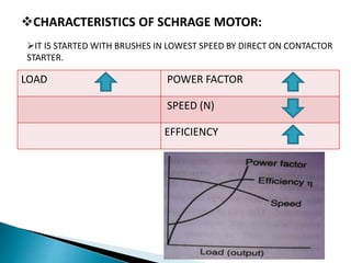
GANDHINAGAR INSTITUTE OF
TECHNOLOGY
Presentation on ::
PRESENTATION BY:
NAROLA KAUSHAL J.
(140123109006)
PANCHAL SIDDHARTH A.
(140123109013)
 GUIDED BY :
Prof. SUPRAJA MAM
WE ARE INTRODUTION TWO MOTORS:
(1)THREE PHASE SCHRAGE MOTOR
(2)REPULSION MOTOR
 SCHRAGE Motors:
 It is use commutator for taking current from supply &
producing unidirectional torque.
 It is work on AC & DC Supply.
Two type of AC Commutator Motors,
1. Single phase AC Commutator motors
2. Three phase AC Commutator motors
Detail study of the following:
(1)Introduction
(2)Construction details
(3)Working
(4)Characteristics
(5)Advantages
(6)Disadvantages
(7)uses
(1)INTRODUCTION:
 This motor is three phase, A.C commutator motor.
 It is basically an circuit for speed control.
 It’s disadvantages is that speed cannot be varied easily.
 It is an inverted induction motor with unibuilt frequency
convertor.
(2) CONSTRUCTIONAL DETAILS:
 ROTOR:
It is cylindrical part made of silicon steel.
It is fitted on shaft and shaft is free to rotate.
STATOR:
It is a outer cylindrical part.
Stator core is made up of silicon steel stampings and slots to accommodate stator.
COMMUTATOR:
It is made up of copper segments insulated by mica segments of commutator.
It is fitted on the same shaft on which the rotor is fitted.
SLIP RINGS & BRUSHES:
The slip rings are made of phosporbronze.
A unit of three slip rings is mounted on the shaft.
Rotor winding is connected to the slip rings carbon brushes.
The power is fed to the rotor via brushes and slip rings.
The function of brushes
is to collect the required
e.m.f from the commutator
and to inject it into
stator secondary winding.
(3) WORKING:
The 3-phase,50 Hz, supply is connected to the rotor primary winding through
slip rings.
The working flux in the air gap is produced.
Regulating winding is housed in the upper portion of the slots.
The primary and secondary winding are just as of induction motor and thus
e.m.f induced in the secondary winding
by induction motor action.
The line frequency voltage induced
in the regulating winding is
converted to the slip frequency
by commutator and injected into
secondary winding.
LOAD POWER FACTOR
SPEED (N)
EFFICIENCY
IT IS STARTED WITH BRUSHES IN LOWEST SPEED BY DIRECT ON CONTACTOR
STARTER.
CHARACTERISTICS OF SCHRAGE MOTOR:
ADVANTAGES:
Wide variation of speed ranges are obtained.
Speed control is simpler.
P.F can be adjusted easily.
DISADVANTAGES:
Complicated structure.
More losses.
Efficiency is less.
USES OF SCHRAGE MOTOR:
Paper mills
Spinning mills
Cranes
Hoists
Boiler drought fans
Textile machinery
 CONSTRUCTIONAL DETAILS:
1) STATOR
2) ROTOR
3) COMMUTATOR
4) BRUSHES
(1) STATOR & STATOR WINDINGS:
 Non salient type distributed.
 It is put in the stator slots.
 It is wound for 4,6,8 poles.
(2) ROTOR:
It is same as armature of D.C motor.
It is having slots in which lap or wave winding is put.
(3) COMMUTATOR:
It is made of Cu and mica segments.
It is connected to the commutator segments.
(4) CARBON BRUSHES:
They are placed in the holder & kept touching with commulator.
The brushes are shorted by connecting directly with a cu wire.
VERTICAL BRUSH AXIS:
If brush axis is vertical the direction of current and e.m.f will be shown.
E.M.F induced in the armature conductor will be an such direction that
magnetic effect produced by if will oppose the stator flux.
The rotor will behave like electromagnet and N & S polarities are developed
on it.
N pole portion of rotor will exactly facing the stator pole.
S pole formed on the rotor will be exactly facing the s pole of stator.
HOROZONTAL BRUSH AXIS:
This brush axis is perpendicular to stator magnetic axis.
In case voltage will be produced but the brush position being horizontal & the
voltage will be neutralized.
Voltage will be zero between brushes.
So current will be zero hence there will not be any torque produced.
Thus motor will not start in brush position if vertical or horizontal.
The speed of this motor can be changed by shifting the brushes.
The direction of rotation can be change by shifting brushes in the
reversed direction.
 DROWBACKS OF REPULSION MOTOR:
Very low power factor.
Very high speed at no load.
Speed not constant but varies with load.
Poor commutation and heavy sparking.
 APPLICATIONS:
Mixing m/c refrigerator.
Grinding devices.
Pumps
Compressors
Lift
Floor polishing machine
COMMUTATOR MOTOR

COMMUTATOR MOTOR

  • 1.
    GANDHINAGAR INSTITUTE OF TECHNOLOGY Presentationon :: PRESENTATION BY: NAROLA KAUSHAL J. (140123109006) PANCHAL SIDDHARTH A. (140123109013)  GUIDED BY : Prof. SUPRAJA MAM
  • 2.
    WE ARE INTRODUTIONTWO MOTORS: (1)THREE PHASE SCHRAGE MOTOR (2)REPULSION MOTOR
  • 3.
     SCHRAGE Motors: It is use commutator for taking current from supply & producing unidirectional torque.  It is work on AC & DC Supply. Two type of AC Commutator Motors, 1. Single phase AC Commutator motors 2. Three phase AC Commutator motors
  • 4.
    Detail study ofthe following: (1)Introduction (2)Construction details (3)Working (4)Characteristics (5)Advantages (6)Disadvantages (7)uses
  • 5.
    (1)INTRODUCTION:  This motoris three phase, A.C commutator motor.  It is basically an circuit for speed control.  It’s disadvantages is that speed cannot be varied easily.  It is an inverted induction motor with unibuilt frequency convertor.
  • 6.
    (2) CONSTRUCTIONAL DETAILS: ROTOR: It is cylindrical part made of silicon steel. It is fitted on shaft and shaft is free to rotate. STATOR: It is a outer cylindrical part. Stator core is made up of silicon steel stampings and slots to accommodate stator. COMMUTATOR: It is made up of copper segments insulated by mica segments of commutator. It is fitted on the same shaft on which the rotor is fitted.
  • 7.
    SLIP RINGS &BRUSHES: The slip rings are made of phosporbronze. A unit of three slip rings is mounted on the shaft. Rotor winding is connected to the slip rings carbon brushes. The power is fed to the rotor via brushes and slip rings. The function of brushes is to collect the required e.m.f from the commutator and to inject it into stator secondary winding.
  • 8.
    (3) WORKING: The 3-phase,50Hz, supply is connected to the rotor primary winding through slip rings. The working flux in the air gap is produced. Regulating winding is housed in the upper portion of the slots. The primary and secondary winding are just as of induction motor and thus e.m.f induced in the secondary winding by induction motor action. The line frequency voltage induced in the regulating winding is converted to the slip frequency by commutator and injected into secondary winding.
  • 9.
    LOAD POWER FACTOR SPEED(N) EFFICIENCY IT IS STARTED WITH BRUSHES IN LOWEST SPEED BY DIRECT ON CONTACTOR STARTER. CHARACTERISTICS OF SCHRAGE MOTOR:
  • 10.
    ADVANTAGES: Wide variation ofspeed ranges are obtained. Speed control is simpler. P.F can be adjusted easily. DISADVANTAGES: Complicated structure. More losses. Efficiency is less. USES OF SCHRAGE MOTOR: Paper mills Spinning mills Cranes Hoists Boiler drought fans Textile machinery
  • 11.
     CONSTRUCTIONAL DETAILS: 1)STATOR 2) ROTOR 3) COMMUTATOR 4) BRUSHES (1) STATOR & STATOR WINDINGS:  Non salient type distributed.  It is put in the stator slots.  It is wound for 4,6,8 poles.
  • 12.
    (2) ROTOR: It issame as armature of D.C motor. It is having slots in which lap or wave winding is put. (3) COMMUTATOR: It is made of Cu and mica segments. It is connected to the commutator segments. (4) CARBON BRUSHES: They are placed in the holder & kept touching with commulator. The brushes are shorted by connecting directly with a cu wire.
  • 13.
    VERTICAL BRUSH AXIS: Ifbrush axis is vertical the direction of current and e.m.f will be shown.
  • 14.
    E.M.F induced inthe armature conductor will be an such direction that magnetic effect produced by if will oppose the stator flux. The rotor will behave like electromagnet and N & S polarities are developed on it. N pole portion of rotor will exactly facing the stator pole. S pole formed on the rotor will be exactly facing the s pole of stator. HOROZONTAL BRUSH AXIS: This brush axis is perpendicular to stator magnetic axis. In case voltage will be produced but the brush position being horizontal & the voltage will be neutralized. Voltage will be zero between brushes. So current will be zero hence there will not be any torque produced.
  • 15.
    Thus motor willnot start in brush position if vertical or horizontal. The speed of this motor can be changed by shifting the brushes. The direction of rotation can be change by shifting brushes in the reversed direction.
  • 16.
     DROWBACKS OFREPULSION MOTOR: Very low power factor. Very high speed at no load. Speed not constant but varies with load. Poor commutation and heavy sparking.  APPLICATIONS: Mixing m/c refrigerator. Grinding devices. Pumps Compressors Lift Floor polishing machine