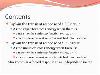
The document discusses the transient response of RC and RL circuits, explaining how capacitors and inductors store energy when subjected to step function sources or switched voltage/current sources. It details the determination of final conditions for capacitor voltage and inductor current, emphasizing the importance of time constants and superposition in circuit analysis. General equations for forced responses in both types of circuits are also provided, noting that steady-state is reached after approximately 5 time constants.
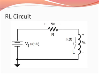
![RL Circuit
[ ]τ/)(1
1
1
1)(
0
0
ott
L
L
L
R
L
e
R
V
tI
L
V
I
L
R
dt
dI
VRI
dt
dI
−−
−=
=−+
=−+
R
L
=τ
dt
dI
LV
RVII
VVV
L
L
RRL
RL
=
==
=++−
/
01](https://image.slidesharecdn.com/initialandfinalconditionforcircuit-160723091412/85/Initial-and-final-condition-for-circuit-10-320.jpg)
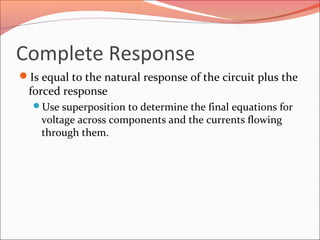
![General Equations
[ ]
[ ]
[ ]
[ ]
RL
eII
L
tV
eIIItI
RC
eVV
C
tI
eVVVtV
t
LLL
t
LLLL
t
CCC
t
CCCC
/
)0()()(
)()0()()(
)0()()(
)()0()()(
/
/
/
/
=
−∞=
∞−+∞=
=
−∞=
∞−+∞=
−
−
−
−
τ
τ
τ
τ
τ
τ
τ
τ
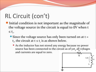
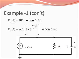
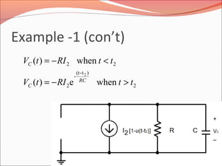
When a
voltage or
current source
changes its
magnitude at
t= 0s in a
simple RC or
RL circuit.
Equations for a simple RC circuit
Equations for a simple RL circuit](https://image.slidesharecdn.com/initialandfinalconditionforcircuit-160723091412/85/Initial-and-final-condition-for-circuit-18-320.jpg)
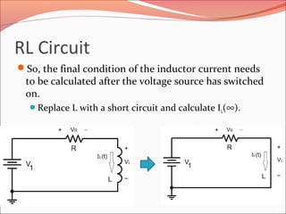
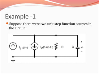
![Summary
The final condition for:
the capacitor voltage (Vo) is determined by replacing the
capacitor with an open circuit and then calculating the
voltage across the terminals.
The inductor current (Io) is determined by replacing the
inductor with a short circuit and then calculating the current
flowing through the short.
The time constant for:
an RC circuit is τ = RC and an RL circuit is τ = L/R
The general equations for the forced response of:
the voltage across a capacitor is
the current through an inductor is
[ ]
[ ] o
tt
oL
o
tt
oC
tteItI
tteVtV
o
o
>−=
>−=
−−
−−
when1)(
when1)(
/)(
/)(
τ
τ](https://image.slidesharecdn.com/initialandfinalconditionforcircuit-160723091412/85/Initial-and-final-condition-for-circuit-19-320.jpg)
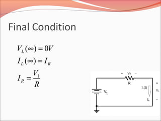
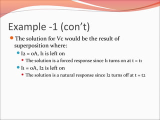
![Summary
General equations when the magnitude of a voltage
or current source in the circuit changes at t = 0s for
the:
voltage across a capacitor is
current through an inductor is
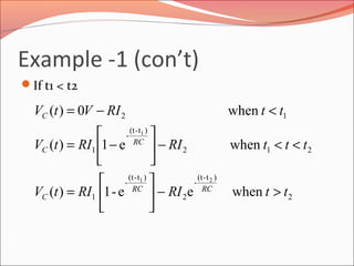
Superposition should be used if there are multiple
voltage and/or current sources that change the
magnitude of their output as a function of time.
[ ]
[ ] τ
τ
/
/
)()0()()(
)()0()()(
t
LLLL
t
CCCC
eIIItI
eVVVtV
−
−
∞−+∞=
∞−+∞=](https://image.slidesharecdn.com/initialandfinalconditionforcircuit-160723091412/85/Initial-and-final-condition-for-circuit-20-320.jpg)