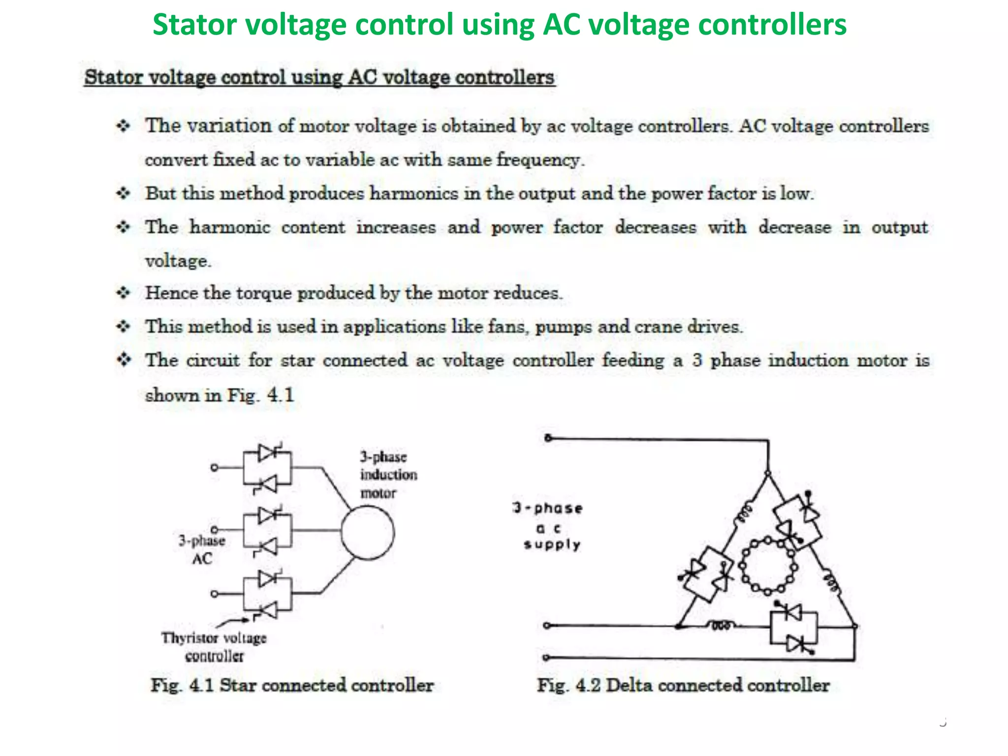
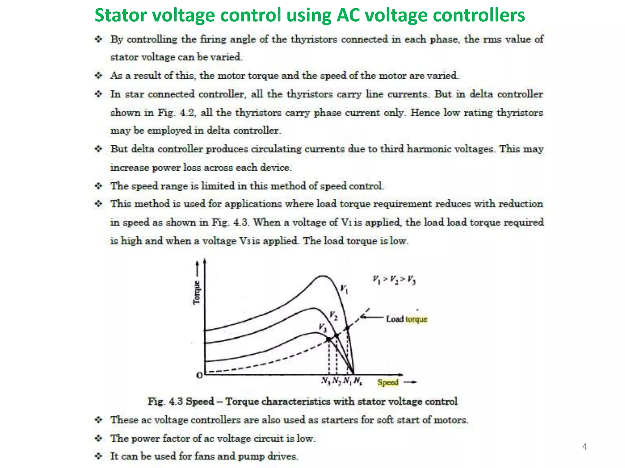
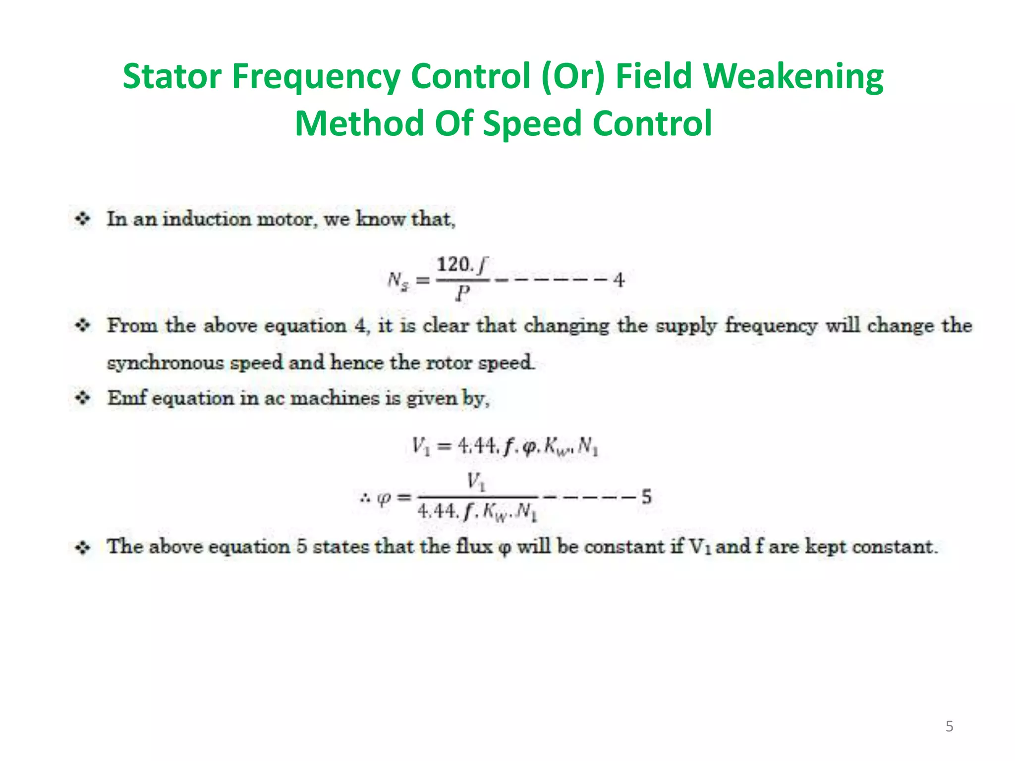
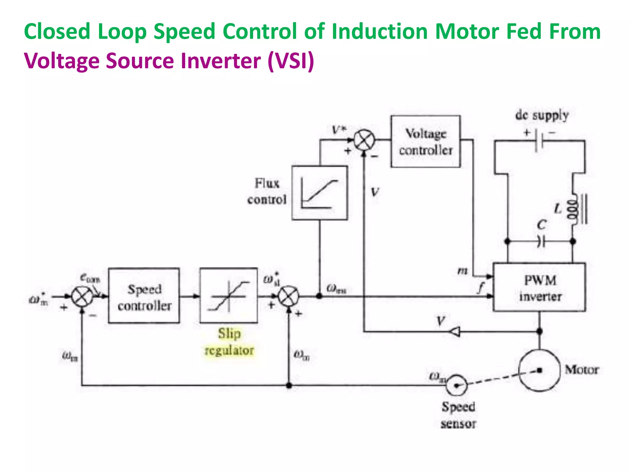
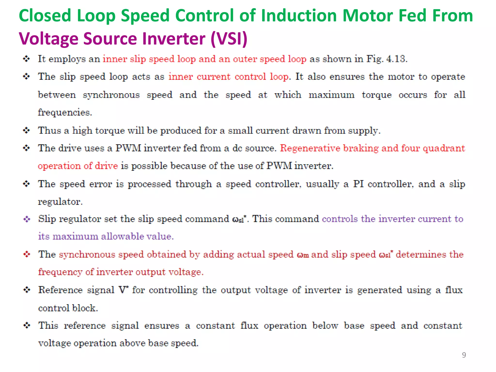
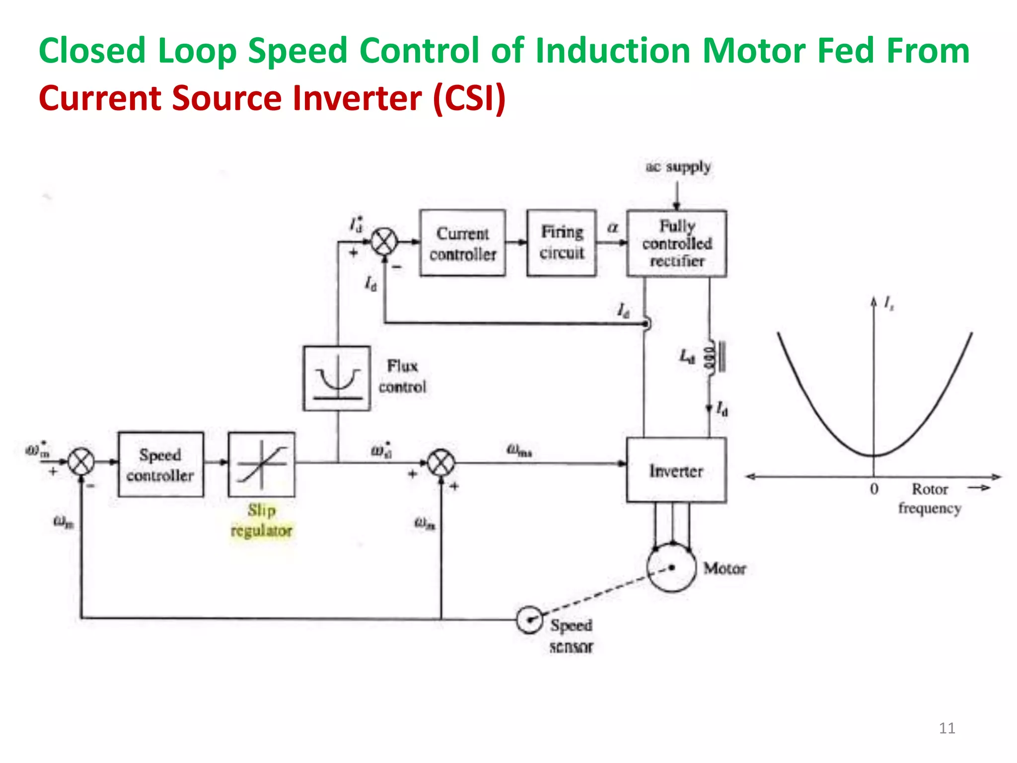
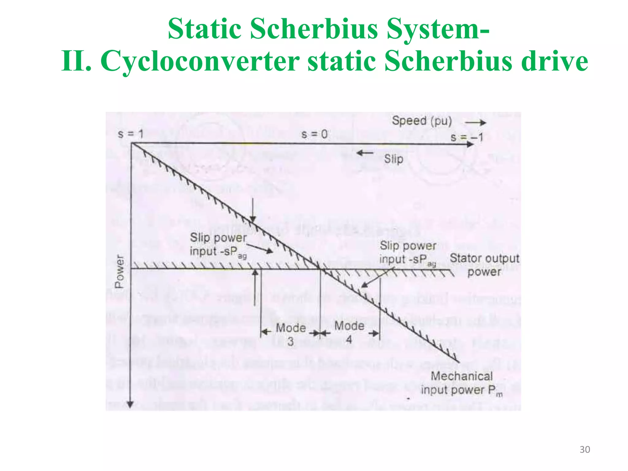
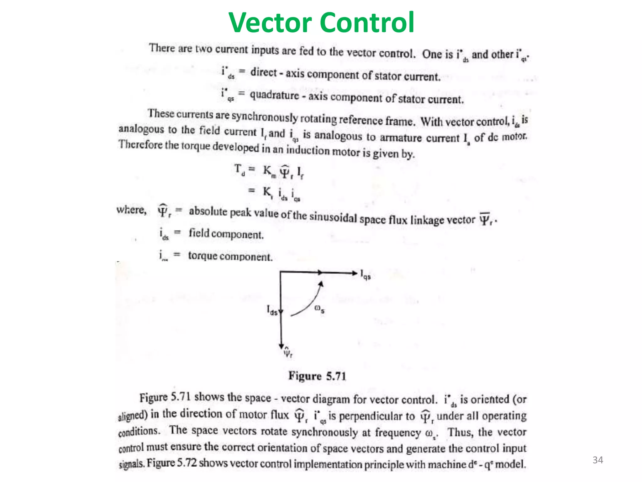
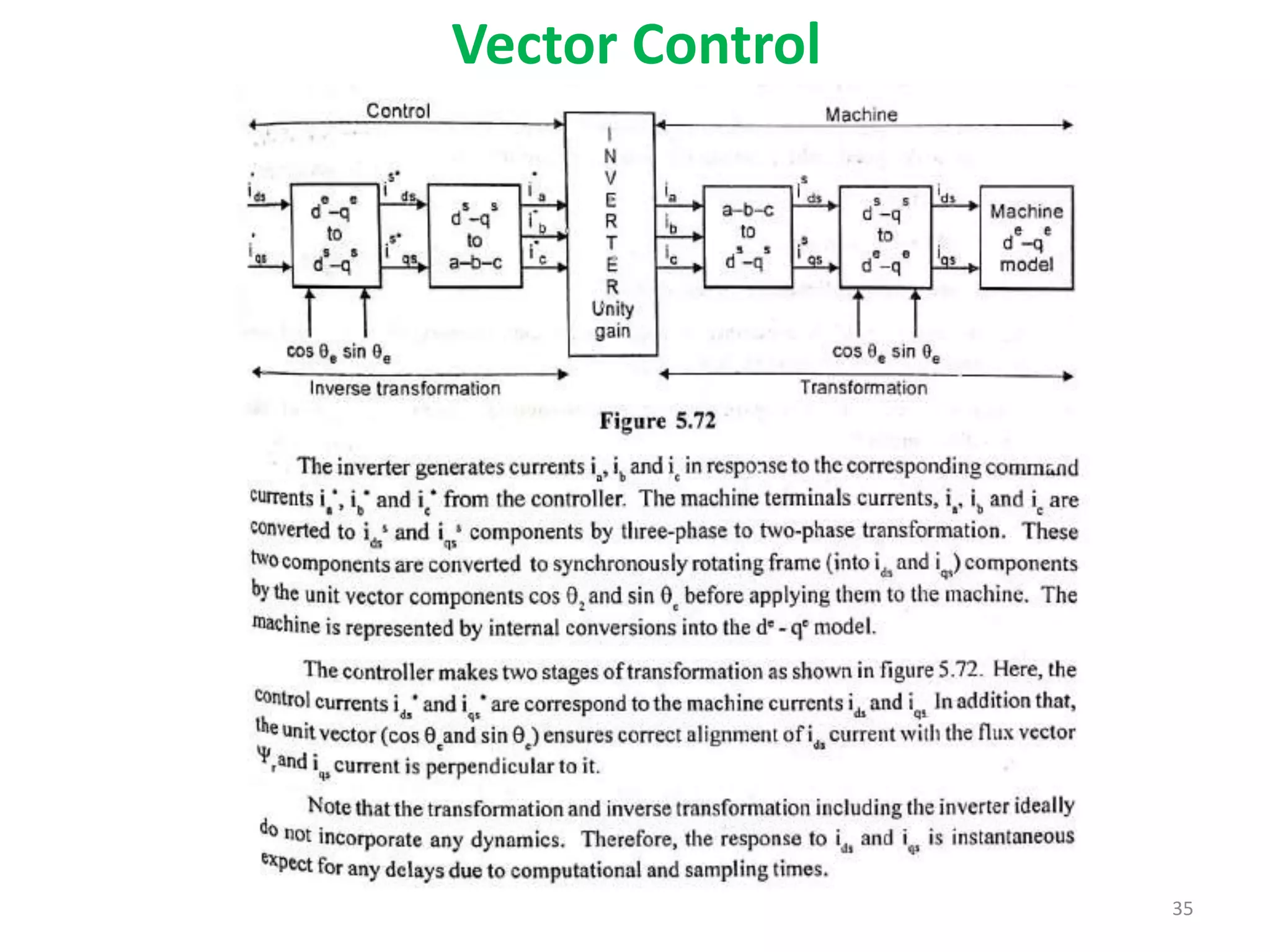
Unit-3
Induction Motor Drives
Speed Control Methods of Induction
Motor Drives
2
3
Stator voltage control using AC voltage controllers
4
Stator voltage control using AC voltage controllers
5
Stator Frequency Control (Or) Field Weakening
Method Of Speed Control
6
Stator Frequency Control (Or) Field Weakening
Method Of Speed Control
V/F Control
• Refer your Class notes
7
Closed Loop Speed Control of Induction Motor Fed From
Voltage Source Inverter (VSI)
9
Closed Loop Speed Control of Induction Motor Fed From
Voltage Source Inverter (VSI)
10
Closed Loop Speed Control of Induction Motor Fed From
Voltage Source Inverter (VSI)
11
Closed Loop Speed Control of Induction Motor Fed From
Current Source Inverter (CSI)
12
Closed Loop Speed Control of Induction Motor Fed From
Current Source Inverter (CSI)
13
Closed Loop Speed Control of Induction Motor Fed From
Current Source Inverter (CSI)
14
SLIP POWER RECOVERY SCHEME
• In rotor resistance control method of speed control, the slip power is wasted
in the external resistance and hence the efficiency reduces.
• However instead of wasting the slip power in external resistor, it can be
recovered and supplied back in order to improve the overall efficiency.
• This scheme of recovering the power is called slip power recovery scheme
and this is done by connecting an external source of emf of slip frequency
to the rotor circuit.
• The injected emf can either oppose the rotor induced emf or aids the rotor
induced emf.
• If it opposes the rotor induced emf, the total rotor resistance increases and
hence speed decreases.
• If the injected emf aids the main rotor emf, the total resistance decreases
and hence speed increases.
• Therefore by injecting induced emf in rotor circuit, the speed can be easily
controlled.
15
Types of Slip Power Recovery Scheme
The slip power recovery system can be classified into two types,
1. Kramer system:
a. Conventional Kramer system.
b. Static Kramer system.
2. Scherbius system
a. Conventional Scherbius system.
b. Static Scherbius system.
i. DC Link static Scherbius drive
ii. Cycloconverter static Scherbius drive
16
Static Kramer system
• In rotor resistance control method, slip power is wasted in
rotor circuit resistance.
• Instead of wasting slip power in rotor circuit resistance, it can
be converted to 50 Hz ac and pumped back to the line.
• Here, slip power can flow only in one direction.
• This method of drive is called static Kramer drive.
• It offers speed control for sub-synchronous speed only i.e.,
speed can be controlled only less than the synchronous speed.
17
18
Static Kramer system
Static Scherbius System-
I. DC link static Scherbius drive
• This system consists of SRIM, 2 number of phase controlled
bridges, smoothing inductor and step up transformer.
• This system is used for both sub-synchronous speed and super-
synchronous speed operation.
19
Static Scherbius System-
I. DC link static Scherbius drive
20
a. Sub-synchronous speed operation:
• Slip power is removed from rotor ckt. and pumped back into
ac supply.
• When m/c is operated at sub-synchronous speed, phase
controlled bridge 1 operates in rectifier mode and bridge 2
operates in inverter mode.
• In other words, bridge 1 has firing angle less than 900 whereas
bridge 2 has firing angle more than 900.
• The slip power flows from rotor circuit to bridge 1, bridge 2,
transformer and returned to supply.
21
Static Scherbius System-
I. DC link static Scherbius drive
22
Static Scherbius System-
I. DC link static Scherbius drive
b. Super-synchronous speed operation:
Static Scherbius System-
I. DC link static Scherbius drive
b. Super synchronous speed operation:
• Additional power is fed into the rotor circuit at slip frequency.
• When machine is operated at super synchronous speed, phase
controlled bridge 2 should operate in rectifier mode and
bridge 1 in inverter mode.
• In other words, bridge 2 has firing angle less than 900 whereas
bridge 1 has firing angle more than 900.
• The slip power flows from the supply to transformer,
bridge 2 (rectifier), bridge 1 (line commutated inverter) and to
the rotor circuit.
• Near synchronous speed, the rotor voltage is low and forced
commutation must be employed in inverter, which makes the
scheme less attractive.
23
24
Static Scherbius System-
II. Cycloconverter static Scherbius drive
Mode 1: Sub-synchronous motoring
This mode, shown in fig. 5.43(a) is similar to that of the
static Kramer system.
The stator input or air gap power Pag remains constant and the
slip power sPag, which is proportional to slip (which is +ve),
returned back to line through cycloconverter.
, line supplies net mechanical power Pm = (1 – s) Pag consumed
by shaft.
The slip fr. power in rotor creates a rotating field in the same
direction as in stator and rotor speed r corresponds to diff.
(s - sl) b/w these two frequencies.
At slip equal to zero, cycloconverter supplies dc excitation to
rotor and the m/c behave like a standard syn. motor.
25
Static Scherbius System-
II. Cycloconverter static Scherbius drive
Mode 2: Super-synchronous motoring
In this mode, (fig. 5.43b), shaft speed  beyond syn. speed, slip
becomes -ve and slip power is absorbed by rotor.
Slip power sPag supplements air gap power Pag for total mechanical
power output (1 + s) Pag.
The line  supplies slip power in addition to stator i/p power.
During this condition, slip voltage is reversed, so that slip frequency-
induced rotating magnetic field is opposite to that of stator.
26
Static Scherbius System-
II. Cycloconverter static Scherbius drive
Mode 3: Sub-synchronous regeneration:
In regenerative braking condition, (fig. 5.43c), shaft is driven by
load and mech. energy is converted into electrical energy.
With constant -ve shaft torque, mech. power i/p to shaft
Pm=(1-s)Pag  with speed and this equals electrical power fed to
the line.
In subsynchronous speed range, slip s is +ve and air gap power
Pag is -ve.
The slip power sPag is fed to rotor from cycloconverter so that
total air gap power is constant. Slip voltage has a +ve phase
sequence.
At synchronous speed, cycloconverter supplies dc excitation
current to rotor circuit and m/c behaves as a syn. generator.
Main application is a variable – speed wind generating system.
27
Static Scherbius System-
II. Cycloconverter static Scherbius drive
28
Static Scherbius System-
II. Cycloconverter static Scherbius drive
Mode 4: Super- synchronous regeneration.
Super-synchronous regeneration is indicated (fig. 5.43d).
Here, stator o/p power remains constant, but addl. Mech. power
i/p is reflected as slip power o/p.
Now rotor field rotates in opposite direction because
cycloconverter phase sequence is reversed.
Power distribution as a function of slip in subsynchronous and
supersynchronous speed ranged is summarized for all four modes
in figure 5.44, where the operating speed range of 50 percent
about the synchronous speed is indicated.
29
Static Scherbius System-
II. Cycloconverter static Scherbius drive
30
Static Scherbius System-
II. Cycloconverter static Scherbius drive
Advantages:
1. Prob. of commutation near syn. speed disappears.
2. Cycloconverter can easily operate as a phase-controlled rectifier, supplying
dc ct. in rotor and permitting true syn. m/c operation.
3. Near-sinusoidal ct. waves in the rotor, which reduce harmonic loss, and m/c
over excitation capacity that permits leading PF operation on stator side so the
line’s PF is unity.
4. Cycloconverter is to be controlled so that its o/p fr. tracks precisely with slip
fr.
Disadvantages:
1. Cycloconverter cost increases.
2. Control of Scherbius drive is some what complex.
Applications
1. Multi – MW, Variable - speed pumps / generators.
2. Flywheel energy storage systems.
31
Static Scherbius System-
II. Cycloconverter static Scherbius drive
Vector Control of Induction Motor Drives
32
33
Vector Control
34
Vector Control
35
Vector Control

Induction Motor Drives

  • 1.
  • 2.
    Speed Control Methodsof Induction Motor Drives 2
  • 3.
    3 Stator voltage controlusing AC voltage controllers
  • 4.
    4 Stator voltage controlusing AC voltage controllers
  • 5.
    5 Stator Frequency Control(Or) Field Weakening Method Of Speed Control
  • 6.
    6 Stator Frequency Control(Or) Field Weakening Method Of Speed Control
  • 7.
    V/F Control • Referyour Class notes 7
  • 8.
    Closed Loop SpeedControl of Induction Motor Fed From Voltage Source Inverter (VSI)
  • 9.
    9 Closed Loop SpeedControl of Induction Motor Fed From Voltage Source Inverter (VSI)
  • 10.
    10 Closed Loop SpeedControl of Induction Motor Fed From Voltage Source Inverter (VSI)
  • 11.
    11 Closed Loop SpeedControl of Induction Motor Fed From Current Source Inverter (CSI)
  • 12.
    12 Closed Loop SpeedControl of Induction Motor Fed From Current Source Inverter (CSI)
  • 13.
    13 Closed Loop SpeedControl of Induction Motor Fed From Current Source Inverter (CSI)
  • 14.
  • 15.
    SLIP POWER RECOVERYSCHEME • In rotor resistance control method of speed control, the slip power is wasted in the external resistance and hence the efficiency reduces. • However instead of wasting the slip power in external resistor, it can be recovered and supplied back in order to improve the overall efficiency. • This scheme of recovering the power is called slip power recovery scheme and this is done by connecting an external source of emf of slip frequency to the rotor circuit. • The injected emf can either oppose the rotor induced emf or aids the rotor induced emf. • If it opposes the rotor induced emf, the total rotor resistance increases and hence speed decreases. • If the injected emf aids the main rotor emf, the total resistance decreases and hence speed increases. • Therefore by injecting induced emf in rotor circuit, the speed can be easily controlled. 15
  • 16.
    Types of SlipPower Recovery Scheme The slip power recovery system can be classified into two types, 1. Kramer system: a. Conventional Kramer system. b. Static Kramer system. 2. Scherbius system a. Conventional Scherbius system. b. Static Scherbius system. i. DC Link static Scherbius drive ii. Cycloconverter static Scherbius drive 16
  • 17.
    Static Kramer system •In rotor resistance control method, slip power is wasted in rotor circuit resistance. • Instead of wasting slip power in rotor circuit resistance, it can be converted to 50 Hz ac and pumped back to the line. • Here, slip power can flow only in one direction. • This method of drive is called static Kramer drive. • It offers speed control for sub-synchronous speed only i.e., speed can be controlled only less than the synchronous speed. 17
  • 18.
  • 19.
    Static Scherbius System- I.DC link static Scherbius drive • This system consists of SRIM, 2 number of phase controlled bridges, smoothing inductor and step up transformer. • This system is used for both sub-synchronous speed and super- synchronous speed operation. 19
  • 20.
    Static Scherbius System- I.DC link static Scherbius drive 20 a. Sub-synchronous speed operation:
  • 21.
    a. Sub-synchronous speedoperation: • Slip power is removed from rotor ckt. and pumped back into ac supply. • When m/c is operated at sub-synchronous speed, phase controlled bridge 1 operates in rectifier mode and bridge 2 operates in inverter mode. • In other words, bridge 1 has firing angle less than 900 whereas bridge 2 has firing angle more than 900. • The slip power flows from rotor circuit to bridge 1, bridge 2, transformer and returned to supply. 21 Static Scherbius System- I. DC link static Scherbius drive
  • 22.
    22 Static Scherbius System- I.DC link static Scherbius drive b. Super-synchronous speed operation:
  • 23.
    Static Scherbius System- I.DC link static Scherbius drive b. Super synchronous speed operation: • Additional power is fed into the rotor circuit at slip frequency. • When machine is operated at super synchronous speed, phase controlled bridge 2 should operate in rectifier mode and bridge 1 in inverter mode. • In other words, bridge 2 has firing angle less than 900 whereas bridge 1 has firing angle more than 900. • The slip power flows from the supply to transformer, bridge 2 (rectifier), bridge 1 (line commutated inverter) and to the rotor circuit. • Near synchronous speed, the rotor voltage is low and forced commutation must be employed in inverter, which makes the scheme less attractive. 23
  • 24.
    24 Static Scherbius System- II.Cycloconverter static Scherbius drive
  • 25.
    Mode 1: Sub-synchronousmotoring This mode, shown in fig. 5.43(a) is similar to that of the static Kramer system. The stator input or air gap power Pag remains constant and the slip power sPag, which is proportional to slip (which is +ve), returned back to line through cycloconverter. , line supplies net mechanical power Pm = (1 – s) Pag consumed by shaft. The slip fr. power in rotor creates a rotating field in the same direction as in stator and rotor speed r corresponds to diff. (s - sl) b/w these two frequencies. At slip equal to zero, cycloconverter supplies dc excitation to rotor and the m/c behave like a standard syn. motor. 25 Static Scherbius System- II. Cycloconverter static Scherbius drive
  • 26.
    Mode 2: Super-synchronousmotoring In this mode, (fig. 5.43b), shaft speed  beyond syn. speed, slip becomes -ve and slip power is absorbed by rotor. Slip power sPag supplements air gap power Pag for total mechanical power output (1 + s) Pag. The line  supplies slip power in addition to stator i/p power. During this condition, slip voltage is reversed, so that slip frequency- induced rotating magnetic field is opposite to that of stator. 26 Static Scherbius System- II. Cycloconverter static Scherbius drive
  • 27.
    Mode 3: Sub-synchronousregeneration: In regenerative braking condition, (fig. 5.43c), shaft is driven by load and mech. energy is converted into electrical energy. With constant -ve shaft torque, mech. power i/p to shaft Pm=(1-s)Pag  with speed and this equals electrical power fed to the line. In subsynchronous speed range, slip s is +ve and air gap power Pag is -ve. The slip power sPag is fed to rotor from cycloconverter so that total air gap power is constant. Slip voltage has a +ve phase sequence. At synchronous speed, cycloconverter supplies dc excitation current to rotor circuit and m/c behaves as a syn. generator. Main application is a variable – speed wind generating system. 27 Static Scherbius System- II. Cycloconverter static Scherbius drive
  • 28.
    28 Static Scherbius System- II.Cycloconverter static Scherbius drive
  • 29.
    Mode 4: Super-synchronous regeneration. Super-synchronous regeneration is indicated (fig. 5.43d). Here, stator o/p power remains constant, but addl. Mech. power i/p is reflected as slip power o/p. Now rotor field rotates in opposite direction because cycloconverter phase sequence is reversed. Power distribution as a function of slip in subsynchronous and supersynchronous speed ranged is summarized for all four modes in figure 5.44, where the operating speed range of 50 percent about the synchronous speed is indicated. 29 Static Scherbius System- II. Cycloconverter static Scherbius drive
  • 30.
    30 Static Scherbius System- II.Cycloconverter static Scherbius drive
  • 31.
    Advantages: 1. Prob. ofcommutation near syn. speed disappears. 2. Cycloconverter can easily operate as a phase-controlled rectifier, supplying dc ct. in rotor and permitting true syn. m/c operation. 3. Near-sinusoidal ct. waves in the rotor, which reduce harmonic loss, and m/c over excitation capacity that permits leading PF operation on stator side so the line’s PF is unity. 4. Cycloconverter is to be controlled so that its o/p fr. tracks precisely with slip fr. Disadvantages: 1. Cycloconverter cost increases. 2. Control of Scherbius drive is some what complex. Applications 1. Multi – MW, Variable - speed pumps / generators. 2. Flywheel energy storage systems. 31 Static Scherbius System- II. Cycloconverter static Scherbius drive
  • 32.
    Vector Control ofInduction Motor Drives 32
  • 33.
  • 34.
  • 35.