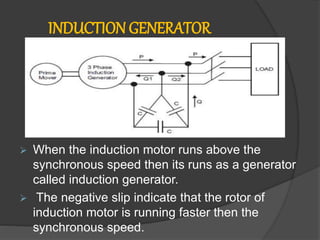
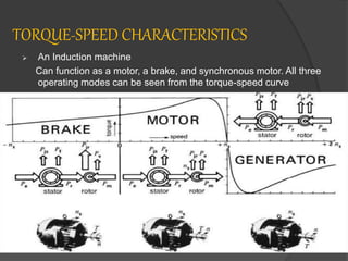
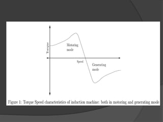
N R A M POLYTECNIC NITTE
DEPARTMENT OF ELECTRICAL AND
ELECTRONICS ENGG
NAME OF THE STUDENT : PRASHANTH KOTIAN
ROLL NO : 53
REGISTER NUMBER : 309EE17304
SUBJECT NAME : TRANSFORMER & AC MOTOR
SUBJECT CODE : 15EE41T
ACTIVITY : INDUCTION GENERATOR
SUBMITTED TO : VISHWANATHAN K
 Induction generator
 Principle of operation
 Induction generator
 Reactive power requirement,
voltage built up & control.
 Advantages & Disadvantages
 Application
CONTENTS
 When the induction motor runs above the
synchronous speed then its runs as a generator
called induction generator.
 The negative slip indicate that the rotor of
induction motor is running faster then the
synchronous speed.
INDUCTION GENERATOR
 Fig. show the induction generator which is
driven by the prime mover such as a wind
turbine is connected to a load.
 When the speed of induction generator
above synchronous speed the active power
delivered by the 3- phase load.
 The corresponding mode of operation of
induction machine is called generating mode
& the slip of induction machine will be
negative.
 The construction of induction generator is
the same as that of induction motor.
TORQUE-SPEED CHARACTERISTICS
 An Induction machine
Can function as a motor, a brake, and synchronous motor. All three
operating modes can be seen from the torque-speed curve
Principle of operation
 When the 3-phase induction motor is driven at a
speed greater than synchronous speed(-ve slip) by
an external prime mover with exciting current
provided either from 3- phase line or capacitor bank.
 The emf and current of slip frequency will appear in
the rotor winding.
 In generating mode of operation, an external prime
mover drives the rotor above the synchronous
speed.
 The stator flux induces currents in the rotor, but
since the opposing rotor flux in now cutting the stator
coils & the motor operates as a generator.
Reactive power requirement, voltage built-up &
control
 The induction generator is not self excited
machine, therefore develop rotating magnetic
field.
 The reactive power is also required for the
connected inductive load to improve the
power factor on the load.
 The induction generator using the delta
connected capacitor bank for the supply of
reactive power is called self excited or
isolated induction generator.
 The reactive power required by the generator
and for the connected inductive load is
supplied by the capacitor bank.
 To achieve a given voltage level in an
induction generator, the capacitor bank must
supply the magnetizing or exciting current
corresponding to that level.
 For a particular value of capacitance, the
curve between the voltage and magnetizing or
capacitive current will be linear.
 The fig. indicates that how the voltage is built
up different values of capacitance.
 At a point P the reactive power demanded by
the generator is equal to the reactive power
supplied by the capacitor bank.
 For a lagging power factor load, the voltage
collapses very rapidly.
ADVANTAGES
 Mechanically & electrically simpler than
other types of generator.
 Construction: simple, robust & rugged.
 Relatively cheaper.
 Requires no brushes & commutator.
 easy in maintenance.
 They do not have to be synchronized to
the supply lines as does a synchronous
generator
DISADVANTAGES
 It is not suitable for separate, isolated
operation
 It consumes rather than supplies
magnetizing KVAR.
 It cannot contribute to the maintenance
of system. voltage levels (this is left
entirely to the synchronous generators
or capacitors).
 In general it has a lower efficiency
APPLICATION
 Induction generator are often used in wind
turbines and small station due to their
ability to produce useful power at varying
rotor speed.
 Particularly suitable for wind generating
stations as in this speed is always a
variable factor.
 They are also very useful automatic
dynamic braking such as for braking
purpose in case of railways.
 Induction generator for a fixed wind turbine
system.

Induction generator

  • 1.
    N R AM POLYTECNIC NITTE DEPARTMENT OF ELECTRICAL AND ELECTRONICS ENGG NAME OF THE STUDENT : PRASHANTH KOTIAN ROLL NO : 53 REGISTER NUMBER : 309EE17304 SUBJECT NAME : TRANSFORMER & AC MOTOR SUBJECT CODE : 15EE41T ACTIVITY : INDUCTION GENERATOR SUBMITTED TO : VISHWANATHAN K
  • 2.
     Induction generator Principle of operation  Induction generator  Reactive power requirement, voltage built up & control.  Advantages & Disadvantages  Application CONTENTS
  • 3.
     When theinduction motor runs above the synchronous speed then its runs as a generator called induction generator.  The negative slip indicate that the rotor of induction motor is running faster then the synchronous speed. INDUCTION GENERATOR
  • 4.
     Fig. showthe induction generator which is driven by the prime mover such as a wind turbine is connected to a load.  When the speed of induction generator above synchronous speed the active power delivered by the 3- phase load.  The corresponding mode of operation of induction machine is called generating mode & the slip of induction machine will be negative.  The construction of induction generator is the same as that of induction motor.
  • 5.
    TORQUE-SPEED CHARACTERISTICS  AnInduction machine Can function as a motor, a brake, and synchronous motor. All three operating modes can be seen from the torque-speed curve
  • 7.
    Principle of operation When the 3-phase induction motor is driven at a speed greater than synchronous speed(-ve slip) by an external prime mover with exciting current provided either from 3- phase line or capacitor bank.  The emf and current of slip frequency will appear in the rotor winding.  In generating mode of operation, an external prime mover drives the rotor above the synchronous speed.  The stator flux induces currents in the rotor, but since the opposing rotor flux in now cutting the stator coils & the motor operates as a generator.
  • 8.
    Reactive power requirement,voltage built-up & control  The induction generator is not self excited machine, therefore develop rotating magnetic field.  The reactive power is also required for the connected inductive load to improve the power factor on the load.  The induction generator using the delta connected capacitor bank for the supply of reactive power is called self excited or isolated induction generator.
  • 9.
     The reactivepower required by the generator and for the connected inductive load is supplied by the capacitor bank.  To achieve a given voltage level in an induction generator, the capacitor bank must supply the magnetizing or exciting current corresponding to that level.  For a particular value of capacitance, the curve between the voltage and magnetizing or capacitive current will be linear.
  • 10.
     The fig.indicates that how the voltage is built up different values of capacitance.  At a point P the reactive power demanded by the generator is equal to the reactive power supplied by the capacitor bank.  For a lagging power factor load, the voltage collapses very rapidly.
  • 11.
    ADVANTAGES  Mechanically &electrically simpler than other types of generator.  Construction: simple, robust & rugged.  Relatively cheaper.  Requires no brushes & commutator.  easy in maintenance.  They do not have to be synchronized to the supply lines as does a synchronous generator
  • 12.
    DISADVANTAGES  It isnot suitable for separate, isolated operation  It consumes rather than supplies magnetizing KVAR.  It cannot contribute to the maintenance of system. voltage levels (this is left entirely to the synchronous generators or capacitors).  In general it has a lower efficiency
  • 13.
    APPLICATION  Induction generatorare often used in wind turbines and small station due to their ability to produce useful power at varying rotor speed.  Particularly suitable for wind generating stations as in this speed is always a variable factor.  They are also very useful automatic dynamic braking such as for braking purpose in case of railways.  Induction generator for a fixed wind turbine system.