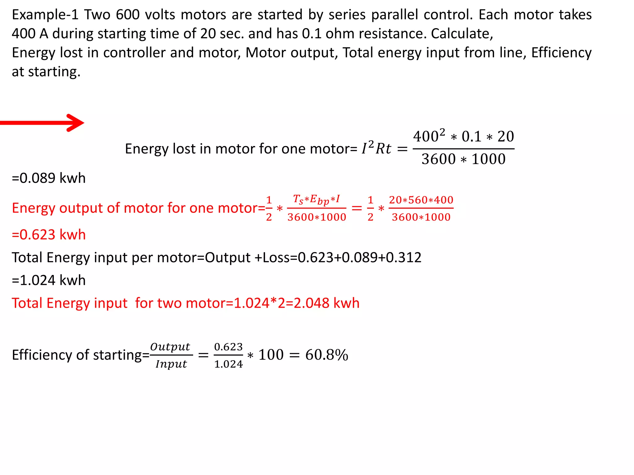
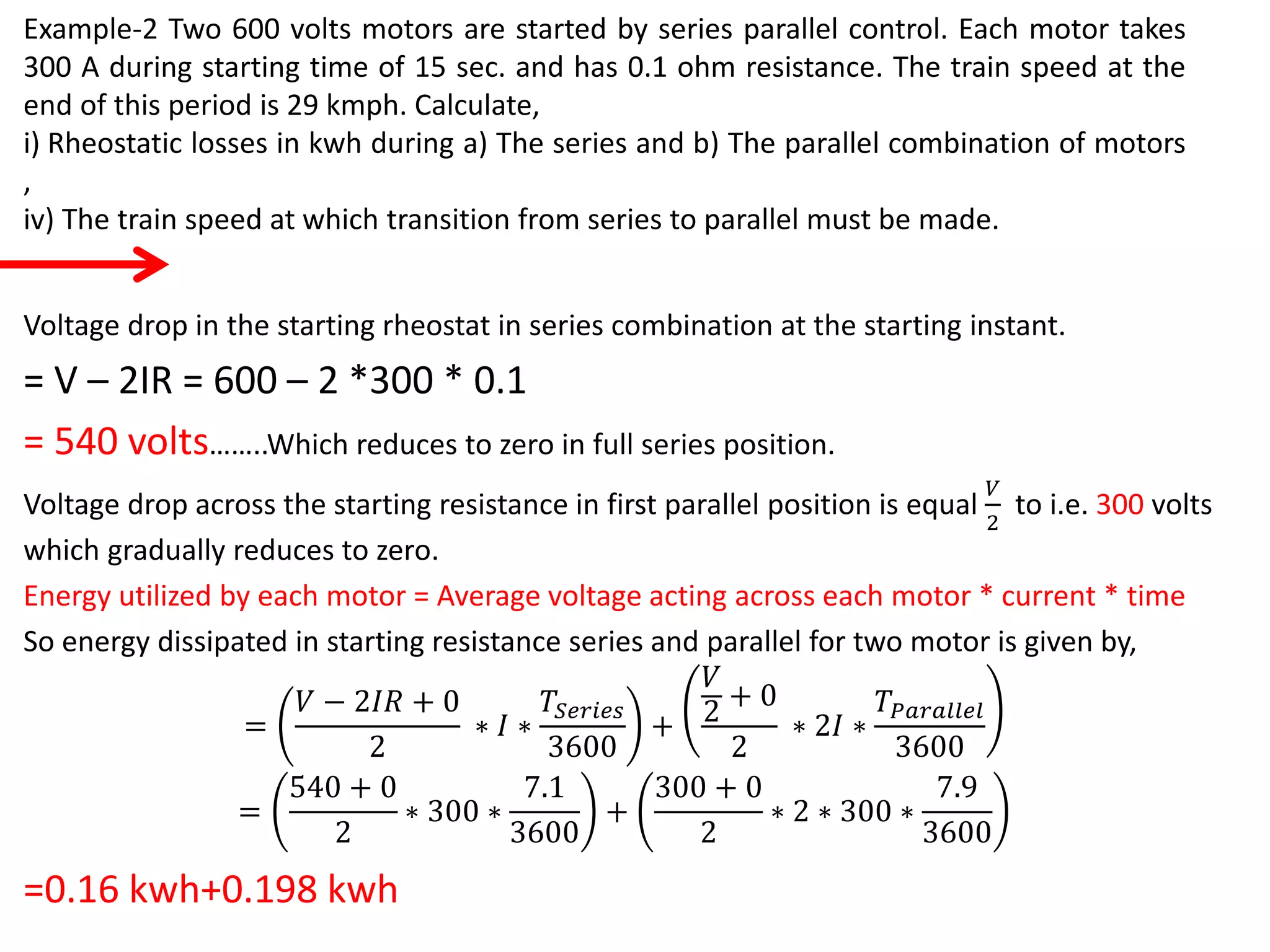
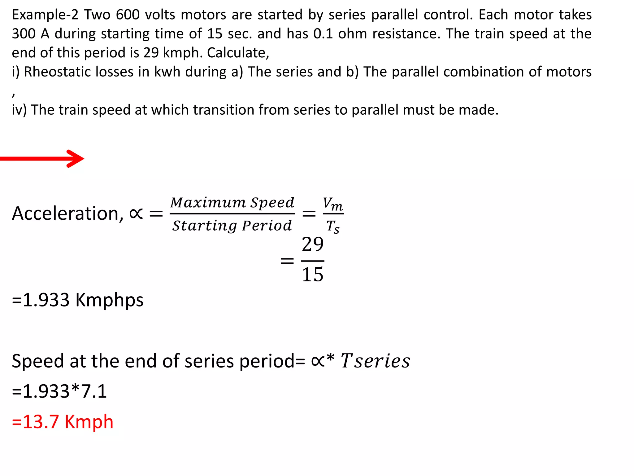
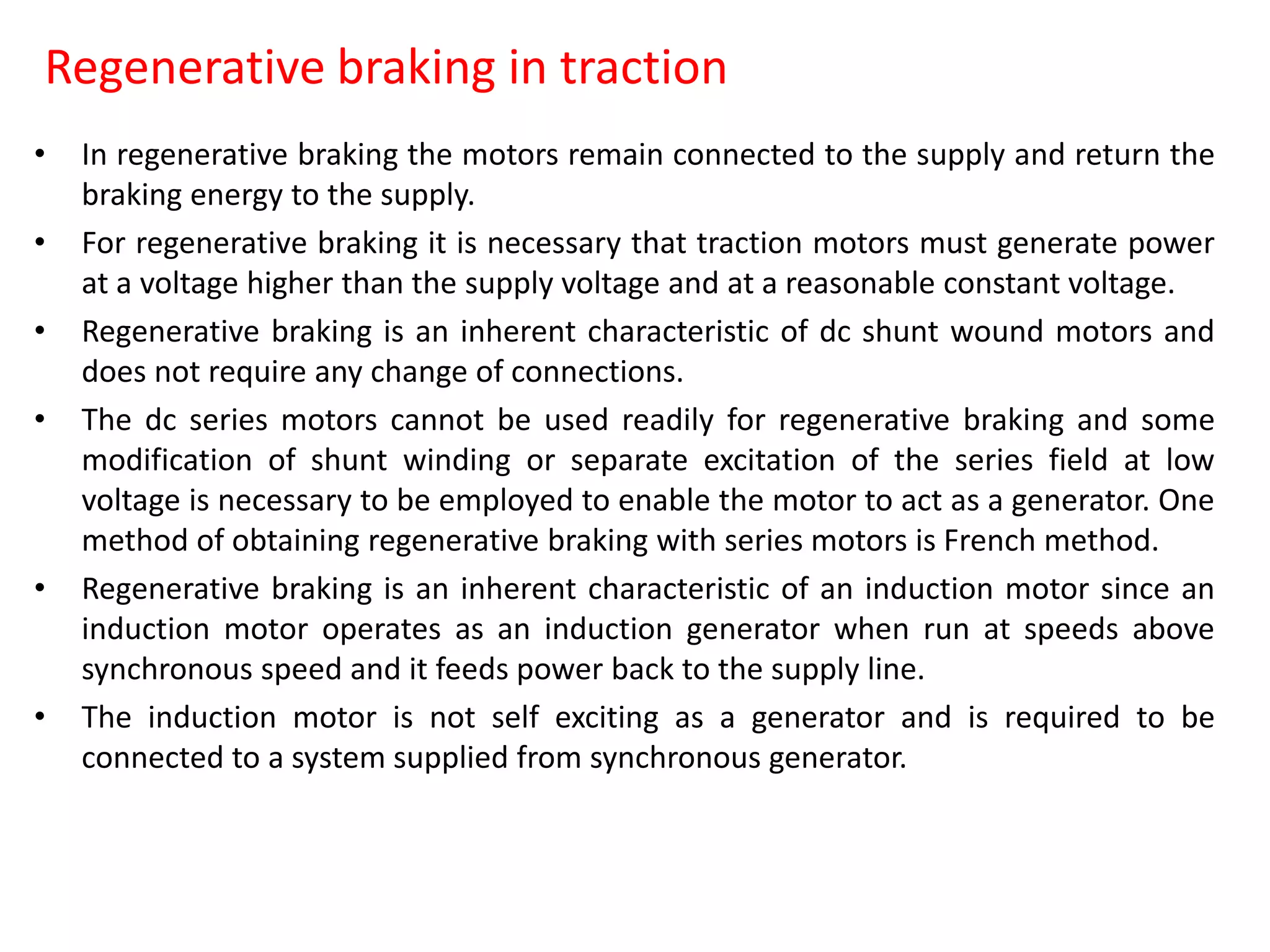
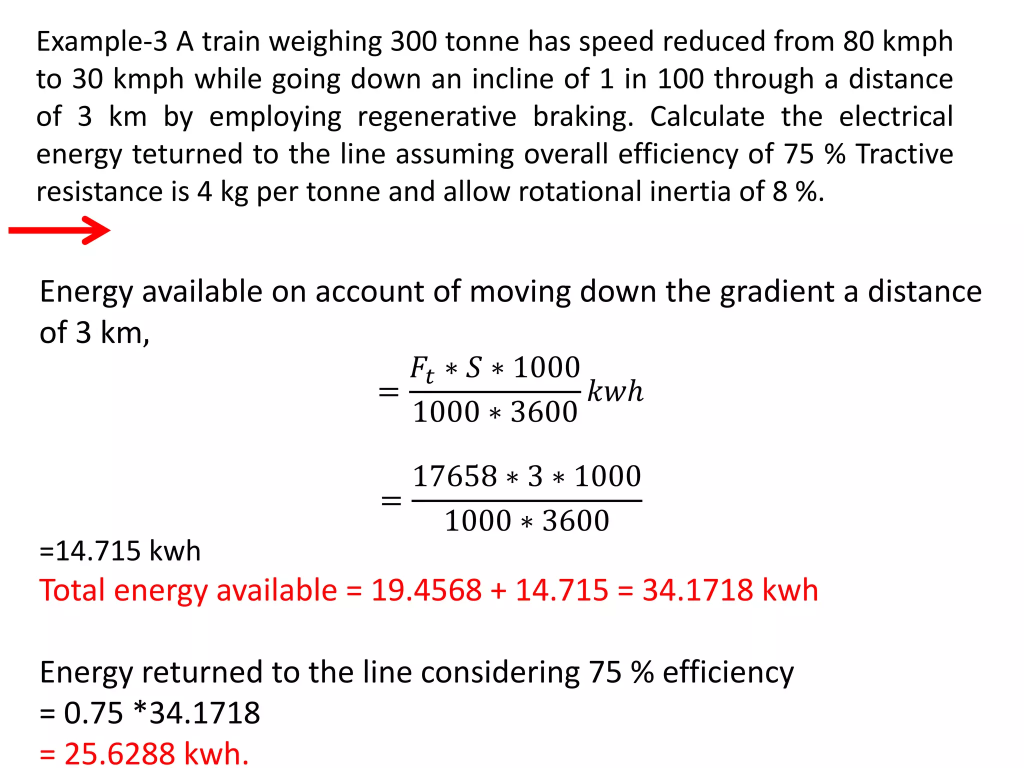
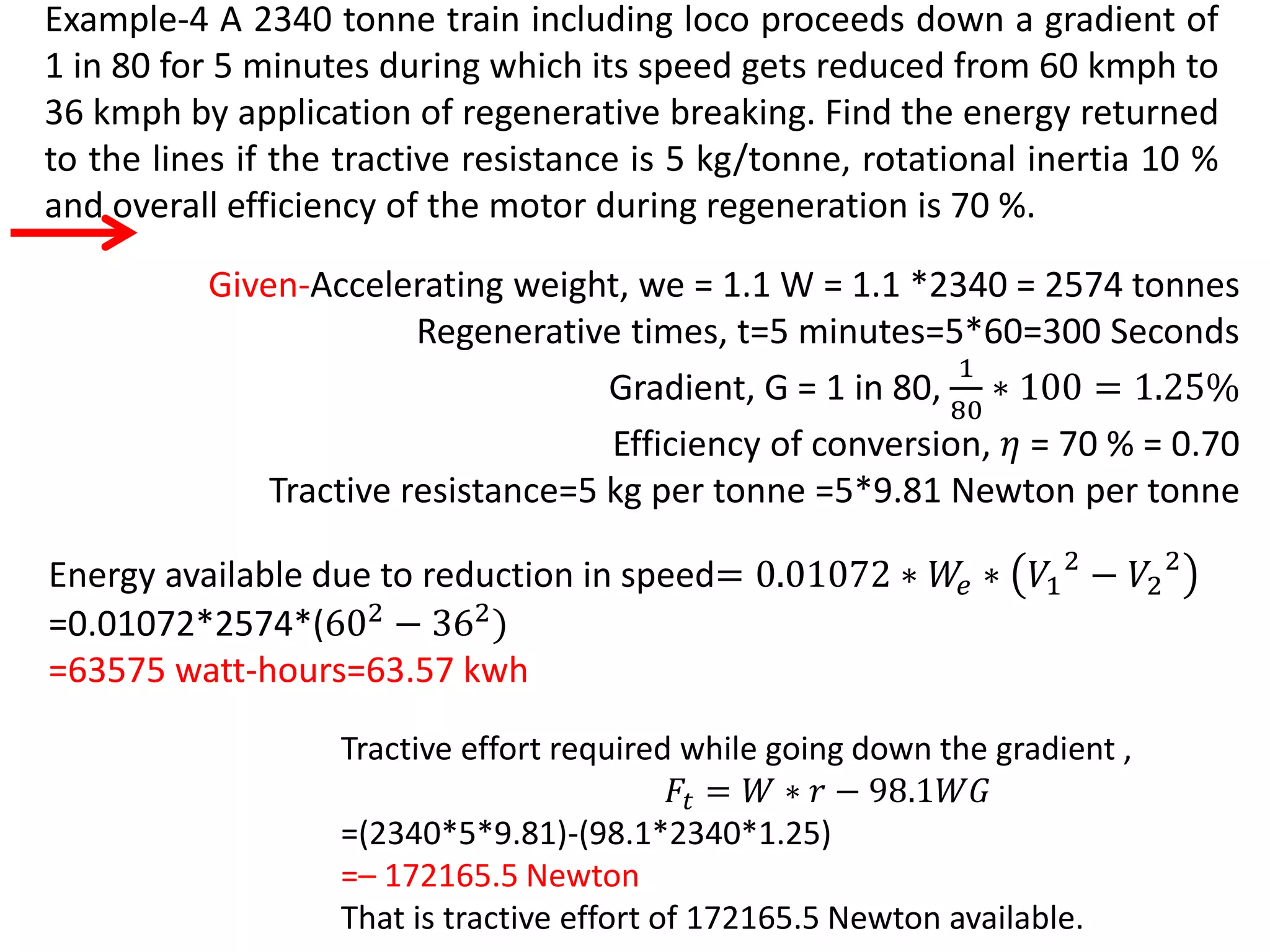
DEPARTMENT OF ELECTRICALENGINEERING
JSPMS
BHIVARABAISAWANTINSTITUTEOFTECHNOLOGYANDRESEARCH,
WAGHOLI,PUNE
A.Y. 2019-20 (SEM-II)
Class: T.E.
Subject: Utilization of Electrical Energy
Prepared by Prof. S. D.
Gadekar
Unit No 6:
Traction Motors and Control
Topics
• Desirable characteristic of traction motor
• Suitability of DC series, AC Series and Linear Induction motor for traction
purpose
• Speed Control of DC Traction Motor
• Series Parallel Control
• Efficiency for series parallel starting of two motors
• Transition Methods
• Numerical on Series Parallel Control
• Self relieving property of DC series motor
• Numerical on Series Parallel Control and maximum speed
• Regenerative braking
• French method of regenerative braking
• Numerical on regenerative braking
Desirable characteristic of traction motor
i) Mechanical features
a) Robust and capable to withstand continuous vibrations
b) The weight of traction motor should be minimum in
order to increase the pay load capacity of the vehicle
c) It must be small in overall dimensions specially in its
overall diameter.
d) It must be totally enclosed type.
Desirable characteristic of traction motor
ii) Electrical characteristics
a) High starting torque
b) Simple speed control
c) Self relieving property – The speed torque characteristics of
the motor should be such that the speed may fall with the
increase in load.
d) Possibility of dynamic or regenerative braking.
e) Capability to withstand voltage fluctuation
f) Capability of withstanding temporary interruption of supply.
g) Overload capacity.
h) Parallel running
Suitability of DC series motor for traction purpose
i) The dc series motor develops high torque at start which is an
essential requirement of traction service.
ii) The series motor is amenable to simple speed control
methods.
iii) In case of dc series motor,
Speed, N ∝
𝑉
∅
∝
1
𝐼
𝐴𝑙𝑠𝑜 𝑇 ∝ ∅𝐼 ∝ 𝐼2
So, Speed, N ∝
1
𝑇
𝑃𝑜𝑤𝑒𝑟 𝑂𝑢𝑡𝑝𝑢𝑡 ∝ 𝑁𝑇 ∝ 𝑇
Thus The power drawn from supply mains varies as the square
root of the load torque.
Suitability of DC series motor for traction purpose
iv) Series motor can be suitable for regenerative braking with some
special arrangements. Such as French method of regenerative
braking.
v) Due to excellent commutation, replacement of brushes is not
required frequently.
vi) Flux varies as the armature current. Thus, torque only depends
on current and independent of line voltage thus unaffected by
variations in the supply voltage.
vii) Up to point of saturation,
𝑇 ∝ 𝐼2
Thus, dc series motors are capable of withstanding excessive loads.
viii) In parallel operations dc series motor share load almost
equally.
Suitability of AC series motor for traction purpose
1. The speed of an ac series motor may be controlled efficiently by taps on a
transformer, which is not possible in case of a dc series motor.
2. Torque - Speed characteristic of the single phase series motor is similar to
that of the dc series motor i.e. high starting torque and decrease in speed
with increase in load making it to have self-relieving property from heavy
excessive load, so such a machine is particularly useful for traction
services.
3. These motors are used for main line services.
4. Single phase AC series motor have better performance (improved power
factor, higher efficiency, improved commutation, better starting and fewer
poles for a given output).
Suitability of Linear Induction motor for traction purpose
The linear synchronous speed Vs of linear induction motor is given as
s = 2 𝞃f meters /second
Where 𝞃 is the pole pitch in meters and f is the supply frequency in Hz.
s =
𝑉𝑠−𝑉
𝑉𝑠
slip of an induction motor.
Where V is the actual speed of rotor plate.
Thrust or force or tractive effort is given as,
F =
𝑃2
𝑉𝑠
Where 𝑃2 is the actual power supplied to the rotor.
Suitability of Linear Induction motor for traction purpose
In linear induction motor, tractive effort is a function of slip s. It
gives thrust-speed characteristic similar to a conventional rotary
induction motor.
Tractive effort, F can be controlled by varying both frequency and
voltage simultaneously so that induction density remains constant.
Transverse edge effect reduces the effective thrust and increases
the losses.
The end effect do not contribute to useful thrust but only towards
motor losses.
Speed Control of DC Traction Motor
1. Rheostatic Control
2. Series Parallel Control
3. Field Control
4. Motor Generator Locomotive control
5. Diesel Electric Locomotive Control
Series Parallel Control
+ -
Step 1
+ -
Step 2
V V
+ -
V
Step 3
+ -
V
Step 4
Efficiency for series parallel starting of two motors-
Let I=Current Amperes; V=Line Voltage volts and T=Accelerating Time seconds.
At the starting instant, both motors are connected in series along with the
starting resistance, the voltage across the motors is zero and across the external
resistance is V volts.
As the motor speed up, the external resistance is gradually reduced to zero.
During this period voltage acting across each motor gradually increases from 0
to
𝑉
2
volts. The time required is
𝑇
2
seconds.
Energy utilized by each motor = Average voltage acting across each motor *
current * time
𝐸𝑛𝑒𝑟𝑔𝑦 𝑈𝑡𝑖𝑙𝑖𝑧𝑒𝑑 𝑏𝑦 𝑒𝑎𝑐ℎ 𝑚𝑜𝑡𝑜𝑟 =
0 +
𝑉
2
2
∗ 𝐼 ∗
𝑇
2
=
𝑉𝐼𝑇
8
𝑊𝑎𝑡𝑡 − 𝑠𝑒𝑐𝑜𝑛𝑑𝑠
𝐸𝑛𝑒𝑟𝑔𝑦 𝑈𝑡𝑖𝑙𝑖𝑧𝑒𝑑 𝑏𝑦 𝑡𝑤𝑜 𝑚𝑜𝑡𝑜𝑟 = 2 ∗
𝑉𝐼𝑇
8
=
𝑉𝐼𝑇
4
𝑊𝑎𝑡𝑡 − 𝑠𝑒𝑐𝑜𝑛𝑑𝑠
𝐸𝑛𝑒𝑟𝑔𝑦 𝑑𝑟𝑎𝑤𝑛 𝑑𝑢𝑟𝑖𝑛𝑔 𝑡ℎ𝑖𝑠 𝑝𝑒𝑟𝑖𝑜𝑑 = 𝑉𝐼 ∗
𝑇
2
=
𝑉𝐼𝑇
2
𝑊𝑎𝑡𝑡 − 𝑠𝑒𝑐𝑜𝑛𝑑𝑠
Efficiency for series parallel starting of two motors-
When the motors are changed from series parallel, the external resistance is
again inserted in the motor circuit.
The voltage across each motor is V/2 volts and the current per motor is I
amperes. Total current drawn from the line is 2I Amp.
The motor speed up, the external resistance is gradually reduced to zero and
voltage across each motor increases gradually from V/2 to V volts.
Energy utilized by each motor = Average voltage acting across each motor *
current * time
𝐸𝑛𝑒𝑟𝑔𝑦 𝑈𝑡𝑖𝑙𝑖𝑧𝑒𝑑 𝑏𝑦 𝑒𝑎𝑐ℎ 𝑚𝑜𝑡𝑜𝑟 =
𝑉
2
+ 𝑉
2
∗ 𝐼 ∗
𝑇
2
=
3𝑉𝐼𝑇
8
𝑊𝑎𝑡𝑡 − 𝑠𝑒𝑐𝑜𝑛𝑑𝑠
𝐸𝑛𝑒𝑟𝑔𝑦 𝑈𝑡𝑖𝑙𝑖𝑧𝑒𝑑 𝑏𝑦 𝑡𝑤𝑜 𝑚𝑜𝑡𝑜𝑟 = 2 ∗
3𝑉𝐼𝑇
8
=
3𝑉𝐼𝑇
4
𝑊𝑎𝑡𝑡 − 𝑠𝑒𝑐𝑜𝑛𝑑𝑠
𝐸𝑛𝑒𝑟𝑔𝑦 𝑑𝑟𝑎𝑤𝑛 𝑑𝑢𝑟𝑖𝑛𝑔 𝑡ℎ𝑖𝑠 𝑝𝑒𝑟𝑖𝑜𝑑 = 𝑉2𝐼 ∗
𝑇
2
= 𝑉𝐼𝑇 𝑊𝑎𝑡𝑡 − 𝑠𝑒𝑐𝑜𝑛𝑑𝑠
Efficiency for series parallel starting of two motors-
Total energy utilised in driving the motors=
𝑉𝐼𝑇
4
+
3𝑉𝐼𝑇
4
=VIT Watt –Seconds
𝐸𝑛𝑒𝑟𝑔𝑦 𝑑𝑟𝑎𝑤𝑛 𝑑𝑢𝑟𝑖𝑛𝑔 𝑡ℎ𝑖𝑠 𝑝𝑒𝑟𝑖𝑜𝑑=
𝑉𝐼𝑇
2
+ 𝑉𝐼𝑇 =
3𝑉𝐼𝑇
2
𝑊𝑎𝑡𝑡 − 𝑠𝑒𝑐𝑜𝑛𝑑𝑠
Overall Starting Efficiency=
𝐸𝑛𝑒𝑟𝑔𝑦 𝑈𝑡𝑖𝑙𝑖𝑧𝑒𝑑
𝐸𝑛𝑒𝑔𝑦 𝐼𝑛𝑝𝑢𝑡
∗ 100
=
𝑉𝐼𝑇
3
2
𝑉𝐼𝑇
∗ 100
= 66.67 %
Transition Methods
The methods of changing-over the connections from
one grouping to another are known as transition
methods.
1. Open-circuit transition
2. Shunt transition
3. Bridge Transition
Transition Methods
1. Open-Circuit Transition
2. Shunt Transition
2. Bridge Transition
Line voltage, V = 600 volts
Current per motor, I = 400 amperes
Starting period, Ts = 20 seconds
Motor resistance, R = 0.1 Ohm
Example-1 Two 600 volts motors are started by series parallel
control. Each motor takes 400 A during starting time of 20 sec. and
has 0.1 ohm resistance. Calculate,
i)Energy lost in controller and motor,
ii) Motor output,
iii) Total energy input from line,
iv) Efficiency at starting.
Back emf of each motor in full series position,
𝐸 𝑏𝑠𝑒 =
𝑉
2
− 𝐼𝑅
𝐸 𝑏𝑠𝑒 =
600
2
−400*0.1=260 Volts
Back emf of each motor in full parallel position,
𝐸 𝑏𝑝 = 600 − 400 ∗ 0.1 = 560 𝑉𝑜𝑙𝑡𝑠
since motors take 20 seconds to build up 560 volts, therefore, time taken to
build up 260 volts emf.
𝑇𝑠𝑒𝑟𝑖𝑒𝑠 =
20
560
∗ 260 = 9.2857 𝑆𝑒𝑐𝑜𝑛𝑑𝑠
𝑇𝑃𝑎𝑟𝑎𝑙𝑙𝑒𝑙 = 𝑇 − 𝑇𝑠𝑒𝑟𝑖𝑒𝑠 = 10.7142 𝑆𝑒𝑐𝑜𝑛𝑑𝑠
Example-1 Two 600 volts motors are started by series parallel control. Each
motor takes 400 A during starting time of 20 sec. and has 0.1 ohm resistance.
Calculate,
Energy lost in controller and motor, Motor output, Total energy input from line,
Efficiency at starting.
Voltage drop in the starting rheostat in series combination at the starting instant.
= V – 2IR = 600 – 2 *400 * 0.1
= 520 volts……..Which reduces to zero in full series position.
Voltage drop across the starting resistance in first parallel position is equal
𝑉
2
to i.e. 300 volts
which gradually reduces to zero.
Energy utilized by each motor = Average voltage acting across each motor * current * time
So energy dissipated in starting resistance series and parallel for two motor is given by,
=
𝑉 − 2𝐼𝑅 + 0
2
∗ 𝐼 ∗
𝑇𝑆𝑒𝑟𝑖𝑒𝑠
3600
+
𝑉
2
+ 0
2
∗ 2𝐼 ∗
𝑇𝑃𝑎𝑟𝑎𝑙𝑙𝑒𝑙
3600
=
520 + 0
2
∗ 400 ∗
9.2857
3600
+
300 + 0
2
∗ 2 ∗ 400 ∗
10.7142
3600
=0.268 kwh+0.357 kwh=0.625
Energy dissipated in starting resistance during series and parallel combination per motor,
=0.312 kwh
Example-1 Two 600 volts motors are started by series parallel control. Each motor takes
400 A during starting time of 20 sec. and has 0.1 ohm resistance. Calculate,
Energy lost in controller and motor, Motor output, Total energy input from line, Efficiency
at starting.
Energy lost in motor for one motor= 𝐼2
𝑅𝑡 =
4002
∗ 0.1 ∗ 20
3600 ∗ 1000
=0.089 kwh
Energy output of motor for one motor=
1
2
∗
𝑇𝑠∗𝐸 𝑏𝑝∗𝐼
3600∗1000
=
1
2
∗
20∗560∗400
3600∗1000
=0.623 kwh
Total Energy input per motor=Output +Loss=0.623+0.089+0.312
=1.024 kwh
Total Energy input for two motor=1.024*2=2.048 kwh
Efficiency of starting=
𝑂𝑢𝑡𝑝𝑢𝑡
𝐼𝑛𝑝𝑢𝑡
=
0.623
1.024
∗ 100 = 60.8%
Example-1 Two 600 volts motors are started by series parallel control. Each motor takes
400 A during starting time of 20 sec. and has 0.1 ohm resistance. Calculate,
Energy lost in controller and motor, Motor output, Total energy input from line, Efficiency
at starting.
Self relieving property of DC series motor
The speed-torque characteristic of the motor should be such that the
speed may fall with the increase in load.
The motors having such speed-torque characteristics are self
protective against excessive overloading as power output of a motor is
proportional to the product of torque and speed.
Speed, N ∝
𝑉
∅
∝
1
𝐼
𝐴𝑙𝑠𝑜 𝑇 ∝ ∅𝐼 ∝ 𝐼2
So, Speed, N ∝
1
𝑇
𝑃𝑜𝑤𝑒𝑟 𝑂𝑢𝑡𝑝𝑢𝑡 ∝ 𝑁𝑇 ∝ 𝑇
Line voltage, V = 600 volts
Current per motor, I = 300 amperes
Starting period, Ts = 15 seconds
Motor resistance, R = 0.1 Ohm
M𝑎𝑥𝑖𝑚𝑢𝑚 𝑆𝑝𝑒𝑒𝑑 𝑉𝑚 = 29 𝑘𝑚𝑝ℎ
Example-2 Two 600 volts motors are started by series parallel
control. Each motor takes 300 A during starting time of 15 sec. and
has 0.1 ohm resistance. The train speed at the end of this period is
29 kmph. Calculate,
i) Rheostatic losses in kwh during a) The series and b) The parallel
combination of motors ,
iv) The train speed at which transition from series to parallel must
be made.
Back emf of each motor in full series position,
𝐸 𝑏𝑠𝑒 =
𝑉
2
− 𝐼𝑅
𝐸 𝑏𝑠𝑒 =
600
2
− 300*0.1=270 Volts
Back emf of each motor in full parallel position,
𝐸 𝑏𝑝 = 600 − 300 ∗ 0.1 = 570 𝑉𝑜𝑙𝑡𝑠
since motors take 20 seconds to build up 570 volts, therefore, time taken
to build up 270 volts emf.
𝑇𝑠𝑒𝑟𝑖𝑒𝑠 =
15
570
∗ 270 = 7.1 𝑆𝑒𝑐𝑜𝑛𝑑𝑠
𝑇𝑃𝑎𝑟𝑎𝑙𝑙𝑒𝑙 = 𝑇 − 𝑇𝑠𝑒𝑟𝑖𝑒𝑠 = 7.9 𝑆𝑒𝑐𝑜𝑛𝑑𝑠
Example-2 Two 600 volts motors are started by series parallel control. Each
motor takes 300 A during starting time of 15 sec. and has 0.1 ohm resistance.
The train speed at the end of this period is 29 kmph. Calculate,
i) Rheostatic losses in kwh during a) The series and b) The parallel combination
of motors ,
iv) The train speed at which transition from series to parallel must be made.
Voltage drop in the starting rheostat in series combination at the starting instant.
= V – 2IR = 600 – 2 *300 * 0.1
= 540 volts……..Which reduces to zero in full series position.
Voltage drop across the starting resistance in first parallel position is equal
𝑉
2
to i.e. 300 volts
which gradually reduces to zero.
Energy utilized by each motor = Average voltage acting across each motor * current * time
So energy dissipated in starting resistance series and parallel for two motor is given by,
=
𝑉 − 2𝐼𝑅 + 0
2
∗ 𝐼 ∗
𝑇𝑆𝑒𝑟𝑖𝑒𝑠
3600
+
𝑉
2
+ 0
2
∗ 2𝐼 ∗
𝑇𝑃𝑎𝑟𝑎𝑙𝑙𝑒𝑙
3600
=
540 + 0
2
∗ 300 ∗
7.1
3600
+
300 + 0
2
∗ 2 ∗ 300 ∗
7.9
3600
=0.16 kwh+0.198 kwh
Example-2 Two 600 volts motors are started by series parallel control. Each motor takes
300 A during starting time of 15 sec. and has 0.1 ohm resistance. The train speed at the
end of this period is 29 kmph. Calculate,
i) Rheostatic losses in kwh during a) The series and b) The parallel combination of motors
,
iv) The train speed at which transition from series to parallel must be made.
Acceleration, ∝ =
𝑀𝑎𝑥𝑖𝑚𝑢𝑚 𝑆𝑝𝑒𝑒𝑑
𝑆𝑡𝑎𝑟𝑡𝑖𝑛𝑔 𝑃𝑒𝑟𝑖𝑜𝑑
=
𝑉 𝑚
𝑇𝑠
=
29
15
=1.933 Kmphps
Speed at the end of series period= ∝* 𝑇𝑠𝑒𝑟𝑖𝑒𝑠
=1.933*7.1
=13.7 Kmph
Example-2 Two 600 volts motors are started by series parallel control. Each motor takes
300 A during starting time of 15 sec. and has 0.1 ohm resistance. The train speed at the
end of this period is 29 kmph. Calculate,
i) Rheostatic losses in kwh during a) The series and b) The parallel combination of motors
,
iv) The train speed at which transition from series to parallel must be made.
Regenerative braking in traction
• In regenerative braking the motors remain connected to the supply and return the
braking energy to the supply.
• For regenerative braking it is necessary that traction motors must generate power
at a voltage higher than the supply voltage and at a reasonable constant voltage.
• Regenerative braking is an inherent characteristic of dc shunt wound motors and
does not require any change of connections.
• The dc series motors cannot be used readily for regenerative braking and some
modification of shunt winding or separate excitation of the series field at low
voltage is necessary to be employed to enable the motor to act as a generator. One
method of obtaining regenerative braking with series motors is French method.
• Regenerative braking is an inherent characteristic of an induction motor since an
induction motor operates as an induction generator when run at speeds above
synchronous speed and it feeds power back to the supply line.
• The induction motor is not self exciting as a generator and is required to be
connected to a system supplied from synchronous generator.
Regenerative braking in traction
Advantages :
i. The wear of the brake shoes and wheel tyres is reduced to considerable extent,
therefore, their life is increased and replacement cost is reduced.
ii. Higher value of braking retardation is obtained so that the vehicle can be brought
to rest quickly and running time is considerably reduced.
iii. Higher speeds are possible while going down the gradients because the high
braking retardation can be obtained with regenerative braking.
Disadvantages :
i. Additional equipment is required for control of regeneration and for protection of
equipment and machines, hence initial as well as maintenance cost is increased.
ii. For regenerative energy the operation of the substations becomes complicated
and difficult.
iii. Regenerative braking is employed down to a speed of 16 kmph, then rheostatic
braking to about 6.5 kmph and then mechanical braking is required to bring
locomotive to rest.
French method of regenerative braking
If there is a single series motor as incase
of a trolley buses, tramways, it is
provided with a main series field
winding connected in parallel with
auxiliary field winding.
During regeneration (braking
period) the auxiliary field
windings are put in series with
each other and are switched
across the supply.
Motoring
Generating
The machine acts as a compound generator slightly differentially compounded.
If there are several motors, we do not require any auxiliary
winding.
During normal running the motors are connected in parallel with
field winding connected in series with their respective armatures.
But, during regeneration the motors are connected such that all
armatures are connected in parallel and series field windings of
all motors are connected in series and placed across the supply.
French method of regenerative braking
Example-3 A train weighing 300 tonne has speed reduced from 80 kmph
to 30 kmph while going down an incline of 1 in 100 through a distance
of 3 km by employing regenerative braking. Calculate the electrical
energy teturned to the line assuming overall efficiency of 75 % Tractive
resistance is 4 kg per tonne and allow rotational inertia of 8 %.
Given-Accelerating weight, we = 1.1 W = 1.1 *300 = 330 tonnes
Distance travelled during period, s = 3 km
Gradient, G = 1 %
Efficiency of conversion, 𝜂 = 75 % = 0.75
Tractive resistance=4 kg per tonne =4*9.81 Newton per tonne
Energy available due to reduction in speed= 0.01072 ∗ 𝑊𝑒 ∗ 𝑉1
2
− 𝑉2
2
=0.01072*330*(802 − 302)
=19456.8 watt-hours=19.45 kwh
Tractive effort required while going down the gradient ,
𝐹𝑡 = 𝑊 ∗ 𝑟 − 98.1𝑊𝐺
=(300*4*9.81)-(98.1*300*1)
=– 17658 Newton
That is tractive effort of 17658 Newton available.
Example-3 A train weighing 300 tonne has speed reduced from 80 kmph
to 30 kmph while going down an incline of 1 in 100 through a distance
of 3 km by employing regenerative braking. Calculate the electrical
energy teturned to the line assuming overall efficiency of 75 % Tractive
resistance is 4 kg per tonne and allow rotational inertia of 8 %.
Energy available on account of moving down the gradient a distance
of 3 km,
=
𝐹𝑡 ∗ 𝑆 ∗ 1000
1000 ∗ 3600
𝑘𝑤ℎ
=
17658 ∗ 3 ∗ 1000
1000 ∗ 3600
=14.715 kwh
Total energy available = 19.4568 + 14.715 = 34.1718 kwh
Energy returned to the line considering 75 % efficiency
= 0.75 *34.1718
= 25.6288 kwh.
Example-4 A 2340 tonne train including loco proceeds down a gradient of
1 in 80 for 5 minutes during which its speed gets reduced from 60 kmph to
36 kmph by application of regenerative breaking. Find the energy returned
to the lines if the tractive resistance is 5 kg/tonne, rotational inertia 10 %
and overall efficiency of the motor during regeneration is 70 %.
Given-Accelerating weight, we = 1.1 W = 1.1 *2340 = 2574 tonnes
Regenerative times, t=5 minutes=5*60=300 Seconds
Gradient, G = 1 in 80,
1
80
∗ 100 = 1.25%
Efficiency of conversion, 𝜂 = 70 % = 0.70
Tractive resistance=5 kg per tonne =5*9.81 Newton per tonne
Energy available due to reduction in speed= 0.01072 ∗ 𝑊𝑒 ∗ 𝑉1
2
− 𝑉2
2
=0.01072*2574*(602 − 362)
=63575 watt-hours=63.57 kwh
Tractive effort required while going down the gradient ,
𝐹𝑡 = 𝑊 ∗ 𝑟 − 98.1𝑊𝐺
=(2340*5*9.81)-(98.1*2340*1.25)
=– 172165.5 Newton
That is tractive effort of 172165.5 Newton available.
Example-4 A 2340 tonne train including loco proceeds down a gradient of 1
in 80 for 5 minutes during which its speed gets reduced from 60 kmph to 36
kmph by application of regenerative breaking. Find the energy returned to
the lines if the tractive resistance is 5 kg/tonne, rotational inertia 10 % and
overall efficiency of the motor during regeneration is 70 %.
Distance moved during regeneration is given by calculating the area
under the speed-time curve for regeneration period,
𝐷 =
𝑉1 + 𝑉2
2
∗
𝑡
3600
=
60 + 36
2
∗
300
3600
D=4 Km
Energy available on account of moving down the gradient a distance
of 3 km,
=
𝐹𝑡 ∗ 𝑆 ∗ 1000
1000 ∗ 3600
𝑘𝑤ℎ
=
172165.5 ∗ 4 ∗ 1000
1000 ∗ 3600
=191.3 kwh
Total energy available = 63.575+191.3= 254.875 kwh
Example-4 A 2340 tonne train including loco proceeds down a gradient of 1
in 80 for 5 minutes during which its speed gets reduced from 60 kmph to 36
kmph by application of regenerative breaking. Find the energy returned to
the lines if the tractive resistance is 5 kg/tonne, rotational inertia 10 % and
overall efficiency of the motor during regeneration is 70 %.
Total energy available = 63.575+191.3= 254.875 kwh
Energy returned to the line considering 75 % efficiency
= 0.70 *254.875
= 178.4 kwh.

Traction Motors and Control

  • 1.
    DEPARTMENT OF ELECTRICALENGINEERING JSPMS BHIVARABAISAWANTINSTITUTEOFTECHNOLOGYANDRESEARCH, WAGHOLI,PUNE A.Y.2019-20 (SEM-II) Class: T.E. Subject: Utilization of Electrical Energy Prepared by Prof. S. D. Gadekar
  • 2.
    Unit No 6: TractionMotors and Control Topics • Desirable characteristic of traction motor • Suitability of DC series, AC Series and Linear Induction motor for traction purpose • Speed Control of DC Traction Motor • Series Parallel Control • Efficiency for series parallel starting of two motors • Transition Methods • Numerical on Series Parallel Control • Self relieving property of DC series motor • Numerical on Series Parallel Control and maximum speed • Regenerative braking • French method of regenerative braking • Numerical on regenerative braking
  • 3.
    Desirable characteristic oftraction motor i) Mechanical features a) Robust and capable to withstand continuous vibrations b) The weight of traction motor should be minimum in order to increase the pay load capacity of the vehicle c) It must be small in overall dimensions specially in its overall diameter. d) It must be totally enclosed type.
  • 4.
    Desirable characteristic oftraction motor ii) Electrical characteristics a) High starting torque b) Simple speed control c) Self relieving property – The speed torque characteristics of the motor should be such that the speed may fall with the increase in load. d) Possibility of dynamic or regenerative braking. e) Capability to withstand voltage fluctuation f) Capability of withstanding temporary interruption of supply. g) Overload capacity. h) Parallel running
  • 5.
    Suitability of DCseries motor for traction purpose i) The dc series motor develops high torque at start which is an essential requirement of traction service. ii) The series motor is amenable to simple speed control methods. iii) In case of dc series motor, Speed, N ∝ 𝑉 ∅ ∝ 1 𝐼 𝐴𝑙𝑠𝑜 𝑇 ∝ ∅𝐼 ∝ 𝐼2 So, Speed, N ∝ 1 𝑇 𝑃𝑜𝑤𝑒𝑟 𝑂𝑢𝑡𝑝𝑢𝑡 ∝ 𝑁𝑇 ∝ 𝑇 Thus The power drawn from supply mains varies as the square root of the load torque.
  • 6.
    Suitability of DCseries motor for traction purpose iv) Series motor can be suitable for regenerative braking with some special arrangements. Such as French method of regenerative braking. v) Due to excellent commutation, replacement of brushes is not required frequently. vi) Flux varies as the armature current. Thus, torque only depends on current and independent of line voltage thus unaffected by variations in the supply voltage. vii) Up to point of saturation, 𝑇 ∝ 𝐼2 Thus, dc series motors are capable of withstanding excessive loads. viii) In parallel operations dc series motor share load almost equally.
  • 7.
    Suitability of ACseries motor for traction purpose 1. The speed of an ac series motor may be controlled efficiently by taps on a transformer, which is not possible in case of a dc series motor. 2. Torque - Speed characteristic of the single phase series motor is similar to that of the dc series motor i.e. high starting torque and decrease in speed with increase in load making it to have self-relieving property from heavy excessive load, so such a machine is particularly useful for traction services. 3. These motors are used for main line services. 4. Single phase AC series motor have better performance (improved power factor, higher efficiency, improved commutation, better starting and fewer poles for a given output).
  • 8.
    Suitability of LinearInduction motor for traction purpose The linear synchronous speed Vs of linear induction motor is given as s = 2 𝞃f meters /second Where 𝞃 is the pole pitch in meters and f is the supply frequency in Hz. s = 𝑉𝑠−𝑉 𝑉𝑠 slip of an induction motor. Where V is the actual speed of rotor plate. Thrust or force or tractive effort is given as, F = 𝑃2 𝑉𝑠 Where 𝑃2 is the actual power supplied to the rotor.
  • 9.
    Suitability of LinearInduction motor for traction purpose In linear induction motor, tractive effort is a function of slip s. It gives thrust-speed characteristic similar to a conventional rotary induction motor. Tractive effort, F can be controlled by varying both frequency and voltage simultaneously so that induction density remains constant. Transverse edge effect reduces the effective thrust and increases the losses. The end effect do not contribute to useful thrust but only towards motor losses.
  • 10.
    Speed Control ofDC Traction Motor 1. Rheostatic Control 2. Series Parallel Control 3. Field Control 4. Motor Generator Locomotive control 5. Diesel Electric Locomotive Control
  • 11.
    Series Parallel Control +- Step 1 + - Step 2 V V + - V Step 3 + - V Step 4
  • 12.
    Efficiency for seriesparallel starting of two motors- Let I=Current Amperes; V=Line Voltage volts and T=Accelerating Time seconds. At the starting instant, both motors are connected in series along with the starting resistance, the voltage across the motors is zero and across the external resistance is V volts. As the motor speed up, the external resistance is gradually reduced to zero. During this period voltage acting across each motor gradually increases from 0 to 𝑉 2 volts. The time required is 𝑇 2 seconds. Energy utilized by each motor = Average voltage acting across each motor * current * time 𝐸𝑛𝑒𝑟𝑔𝑦 𝑈𝑡𝑖𝑙𝑖𝑧𝑒𝑑 𝑏𝑦 𝑒𝑎𝑐ℎ 𝑚𝑜𝑡𝑜𝑟 = 0 + 𝑉 2 2 ∗ 𝐼 ∗ 𝑇 2 = 𝑉𝐼𝑇 8 𝑊𝑎𝑡𝑡 − 𝑠𝑒𝑐𝑜𝑛𝑑𝑠 𝐸𝑛𝑒𝑟𝑔𝑦 𝑈𝑡𝑖𝑙𝑖𝑧𝑒𝑑 𝑏𝑦 𝑡𝑤𝑜 𝑚𝑜𝑡𝑜𝑟 = 2 ∗ 𝑉𝐼𝑇 8 = 𝑉𝐼𝑇 4 𝑊𝑎𝑡𝑡 − 𝑠𝑒𝑐𝑜𝑛𝑑𝑠 𝐸𝑛𝑒𝑟𝑔𝑦 𝑑𝑟𝑎𝑤𝑛 𝑑𝑢𝑟𝑖𝑛𝑔 𝑡ℎ𝑖𝑠 𝑝𝑒𝑟𝑖𝑜𝑑 = 𝑉𝐼 ∗ 𝑇 2 = 𝑉𝐼𝑇 2 𝑊𝑎𝑡𝑡 − 𝑠𝑒𝑐𝑜𝑛𝑑𝑠
  • 13.
    Efficiency for seriesparallel starting of two motors- When the motors are changed from series parallel, the external resistance is again inserted in the motor circuit. The voltage across each motor is V/2 volts and the current per motor is I amperes. Total current drawn from the line is 2I Amp. The motor speed up, the external resistance is gradually reduced to zero and voltage across each motor increases gradually from V/2 to V volts. Energy utilized by each motor = Average voltage acting across each motor * current * time 𝐸𝑛𝑒𝑟𝑔𝑦 𝑈𝑡𝑖𝑙𝑖𝑧𝑒𝑑 𝑏𝑦 𝑒𝑎𝑐ℎ 𝑚𝑜𝑡𝑜𝑟 = 𝑉 2 + 𝑉 2 ∗ 𝐼 ∗ 𝑇 2 = 3𝑉𝐼𝑇 8 𝑊𝑎𝑡𝑡 − 𝑠𝑒𝑐𝑜𝑛𝑑𝑠 𝐸𝑛𝑒𝑟𝑔𝑦 𝑈𝑡𝑖𝑙𝑖𝑧𝑒𝑑 𝑏𝑦 𝑡𝑤𝑜 𝑚𝑜𝑡𝑜𝑟 = 2 ∗ 3𝑉𝐼𝑇 8 = 3𝑉𝐼𝑇 4 𝑊𝑎𝑡𝑡 − 𝑠𝑒𝑐𝑜𝑛𝑑𝑠 𝐸𝑛𝑒𝑟𝑔𝑦 𝑑𝑟𝑎𝑤𝑛 𝑑𝑢𝑟𝑖𝑛𝑔 𝑡ℎ𝑖𝑠 𝑝𝑒𝑟𝑖𝑜𝑑 = 𝑉2𝐼 ∗ 𝑇 2 = 𝑉𝐼𝑇 𝑊𝑎𝑡𝑡 − 𝑠𝑒𝑐𝑜𝑛𝑑𝑠
  • 14.
    Efficiency for seriesparallel starting of two motors- Total energy utilised in driving the motors= 𝑉𝐼𝑇 4 + 3𝑉𝐼𝑇 4 =VIT Watt –Seconds 𝐸𝑛𝑒𝑟𝑔𝑦 𝑑𝑟𝑎𝑤𝑛 𝑑𝑢𝑟𝑖𝑛𝑔 𝑡ℎ𝑖𝑠 𝑝𝑒𝑟𝑖𝑜𝑑= 𝑉𝐼𝑇 2 + 𝑉𝐼𝑇 = 3𝑉𝐼𝑇 2 𝑊𝑎𝑡𝑡 − 𝑠𝑒𝑐𝑜𝑛𝑑𝑠 Overall Starting Efficiency= 𝐸𝑛𝑒𝑟𝑔𝑦 𝑈𝑡𝑖𝑙𝑖𝑧𝑒𝑑 𝐸𝑛𝑒𝑔𝑦 𝐼𝑛𝑝𝑢𝑡 ∗ 100 = 𝑉𝐼𝑇 3 2 𝑉𝐼𝑇 ∗ 100 = 66.67 %
  • 15.
    Transition Methods The methodsof changing-over the connections from one grouping to another are known as transition methods. 1. Open-circuit transition 2. Shunt transition 3. Bridge Transition
  • 16.
  • 17.
  • 18.
  • 19.
    Line voltage, V= 600 volts Current per motor, I = 400 amperes Starting period, Ts = 20 seconds Motor resistance, R = 0.1 Ohm Example-1 Two 600 volts motors are started by series parallel control. Each motor takes 400 A during starting time of 20 sec. and has 0.1 ohm resistance. Calculate, i)Energy lost in controller and motor, ii) Motor output, iii) Total energy input from line, iv) Efficiency at starting.
  • 20.
    Back emf ofeach motor in full series position, 𝐸 𝑏𝑠𝑒 = 𝑉 2 − 𝐼𝑅 𝐸 𝑏𝑠𝑒 = 600 2 −400*0.1=260 Volts Back emf of each motor in full parallel position, 𝐸 𝑏𝑝 = 600 − 400 ∗ 0.1 = 560 𝑉𝑜𝑙𝑡𝑠 since motors take 20 seconds to build up 560 volts, therefore, time taken to build up 260 volts emf. 𝑇𝑠𝑒𝑟𝑖𝑒𝑠 = 20 560 ∗ 260 = 9.2857 𝑆𝑒𝑐𝑜𝑛𝑑𝑠 𝑇𝑃𝑎𝑟𝑎𝑙𝑙𝑒𝑙 = 𝑇 − 𝑇𝑠𝑒𝑟𝑖𝑒𝑠 = 10.7142 𝑆𝑒𝑐𝑜𝑛𝑑𝑠 Example-1 Two 600 volts motors are started by series parallel control. Each motor takes 400 A during starting time of 20 sec. and has 0.1 ohm resistance. Calculate, Energy lost in controller and motor, Motor output, Total energy input from line, Efficiency at starting.
  • 21.
    Voltage drop inthe starting rheostat in series combination at the starting instant. = V – 2IR = 600 – 2 *400 * 0.1 = 520 volts……..Which reduces to zero in full series position. Voltage drop across the starting resistance in first parallel position is equal 𝑉 2 to i.e. 300 volts which gradually reduces to zero. Energy utilized by each motor = Average voltage acting across each motor * current * time So energy dissipated in starting resistance series and parallel for two motor is given by, = 𝑉 − 2𝐼𝑅 + 0 2 ∗ 𝐼 ∗ 𝑇𝑆𝑒𝑟𝑖𝑒𝑠 3600 + 𝑉 2 + 0 2 ∗ 2𝐼 ∗ 𝑇𝑃𝑎𝑟𝑎𝑙𝑙𝑒𝑙 3600 = 520 + 0 2 ∗ 400 ∗ 9.2857 3600 + 300 + 0 2 ∗ 2 ∗ 400 ∗ 10.7142 3600 =0.268 kwh+0.357 kwh=0.625 Energy dissipated in starting resistance during series and parallel combination per motor, =0.312 kwh Example-1 Two 600 volts motors are started by series parallel control. Each motor takes 400 A during starting time of 20 sec. and has 0.1 ohm resistance. Calculate, Energy lost in controller and motor, Motor output, Total energy input from line, Efficiency at starting.
  • 22.
    Energy lost inmotor for one motor= 𝐼2 𝑅𝑡 = 4002 ∗ 0.1 ∗ 20 3600 ∗ 1000 =0.089 kwh Energy output of motor for one motor= 1 2 ∗ 𝑇𝑠∗𝐸 𝑏𝑝∗𝐼 3600∗1000 = 1 2 ∗ 20∗560∗400 3600∗1000 =0.623 kwh Total Energy input per motor=Output +Loss=0.623+0.089+0.312 =1.024 kwh Total Energy input for two motor=1.024*2=2.048 kwh Efficiency of starting= 𝑂𝑢𝑡𝑝𝑢𝑡 𝐼𝑛𝑝𝑢𝑡 = 0.623 1.024 ∗ 100 = 60.8% Example-1 Two 600 volts motors are started by series parallel control. Each motor takes 400 A during starting time of 20 sec. and has 0.1 ohm resistance. Calculate, Energy lost in controller and motor, Motor output, Total energy input from line, Efficiency at starting.
  • 23.
    Self relieving propertyof DC series motor The speed-torque characteristic of the motor should be such that the speed may fall with the increase in load. The motors having such speed-torque characteristics are self protective against excessive overloading as power output of a motor is proportional to the product of torque and speed. Speed, N ∝ 𝑉 ∅ ∝ 1 𝐼 𝐴𝑙𝑠𝑜 𝑇 ∝ ∅𝐼 ∝ 𝐼2 So, Speed, N ∝ 1 𝑇 𝑃𝑜𝑤𝑒𝑟 𝑂𝑢𝑡𝑝𝑢𝑡 ∝ 𝑁𝑇 ∝ 𝑇
  • 24.
    Line voltage, V= 600 volts Current per motor, I = 300 amperes Starting period, Ts = 15 seconds Motor resistance, R = 0.1 Ohm M𝑎𝑥𝑖𝑚𝑢𝑚 𝑆𝑝𝑒𝑒𝑑 𝑉𝑚 = 29 𝑘𝑚𝑝ℎ Example-2 Two 600 volts motors are started by series parallel control. Each motor takes 300 A during starting time of 15 sec. and has 0.1 ohm resistance. The train speed at the end of this period is 29 kmph. Calculate, i) Rheostatic losses in kwh during a) The series and b) The parallel combination of motors , iv) The train speed at which transition from series to parallel must be made.
  • 25.
    Back emf ofeach motor in full series position, 𝐸 𝑏𝑠𝑒 = 𝑉 2 − 𝐼𝑅 𝐸 𝑏𝑠𝑒 = 600 2 − 300*0.1=270 Volts Back emf of each motor in full parallel position, 𝐸 𝑏𝑝 = 600 − 300 ∗ 0.1 = 570 𝑉𝑜𝑙𝑡𝑠 since motors take 20 seconds to build up 570 volts, therefore, time taken to build up 270 volts emf. 𝑇𝑠𝑒𝑟𝑖𝑒𝑠 = 15 570 ∗ 270 = 7.1 𝑆𝑒𝑐𝑜𝑛𝑑𝑠 𝑇𝑃𝑎𝑟𝑎𝑙𝑙𝑒𝑙 = 𝑇 − 𝑇𝑠𝑒𝑟𝑖𝑒𝑠 = 7.9 𝑆𝑒𝑐𝑜𝑛𝑑𝑠 Example-2 Two 600 volts motors are started by series parallel control. Each motor takes 300 A during starting time of 15 sec. and has 0.1 ohm resistance. The train speed at the end of this period is 29 kmph. Calculate, i) Rheostatic losses in kwh during a) The series and b) The parallel combination of motors , iv) The train speed at which transition from series to parallel must be made.
  • 26.
    Voltage drop inthe starting rheostat in series combination at the starting instant. = V – 2IR = 600 – 2 *300 * 0.1 = 540 volts……..Which reduces to zero in full series position. Voltage drop across the starting resistance in first parallel position is equal 𝑉 2 to i.e. 300 volts which gradually reduces to zero. Energy utilized by each motor = Average voltage acting across each motor * current * time So energy dissipated in starting resistance series and parallel for two motor is given by, = 𝑉 − 2𝐼𝑅 + 0 2 ∗ 𝐼 ∗ 𝑇𝑆𝑒𝑟𝑖𝑒𝑠 3600 + 𝑉 2 + 0 2 ∗ 2𝐼 ∗ 𝑇𝑃𝑎𝑟𝑎𝑙𝑙𝑒𝑙 3600 = 540 + 0 2 ∗ 300 ∗ 7.1 3600 + 300 + 0 2 ∗ 2 ∗ 300 ∗ 7.9 3600 =0.16 kwh+0.198 kwh Example-2 Two 600 volts motors are started by series parallel control. Each motor takes 300 A during starting time of 15 sec. and has 0.1 ohm resistance. The train speed at the end of this period is 29 kmph. Calculate, i) Rheostatic losses in kwh during a) The series and b) The parallel combination of motors , iv) The train speed at which transition from series to parallel must be made.
  • 27.
    Acceleration, ∝ = 𝑀𝑎𝑥𝑖𝑚𝑢𝑚𝑆𝑝𝑒𝑒𝑑 𝑆𝑡𝑎𝑟𝑡𝑖𝑛𝑔 𝑃𝑒𝑟𝑖𝑜𝑑 = 𝑉 𝑚 𝑇𝑠 = 29 15 =1.933 Kmphps Speed at the end of series period= ∝* 𝑇𝑠𝑒𝑟𝑖𝑒𝑠 =1.933*7.1 =13.7 Kmph Example-2 Two 600 volts motors are started by series parallel control. Each motor takes 300 A during starting time of 15 sec. and has 0.1 ohm resistance. The train speed at the end of this period is 29 kmph. Calculate, i) Rheostatic losses in kwh during a) The series and b) The parallel combination of motors , iv) The train speed at which transition from series to parallel must be made.
  • 28.
    Regenerative braking intraction • In regenerative braking the motors remain connected to the supply and return the braking energy to the supply. • For regenerative braking it is necessary that traction motors must generate power at a voltage higher than the supply voltage and at a reasonable constant voltage. • Regenerative braking is an inherent characteristic of dc shunt wound motors and does not require any change of connections. • The dc series motors cannot be used readily for regenerative braking and some modification of shunt winding or separate excitation of the series field at low voltage is necessary to be employed to enable the motor to act as a generator. One method of obtaining regenerative braking with series motors is French method. • Regenerative braking is an inherent characteristic of an induction motor since an induction motor operates as an induction generator when run at speeds above synchronous speed and it feeds power back to the supply line. • The induction motor is not self exciting as a generator and is required to be connected to a system supplied from synchronous generator.
  • 29.
    Regenerative braking intraction Advantages : i. The wear of the brake shoes and wheel tyres is reduced to considerable extent, therefore, their life is increased and replacement cost is reduced. ii. Higher value of braking retardation is obtained so that the vehicle can be brought to rest quickly and running time is considerably reduced. iii. Higher speeds are possible while going down the gradients because the high braking retardation can be obtained with regenerative braking. Disadvantages : i. Additional equipment is required for control of regeneration and for protection of equipment and machines, hence initial as well as maintenance cost is increased. ii. For regenerative energy the operation of the substations becomes complicated and difficult. iii. Regenerative braking is employed down to a speed of 16 kmph, then rheostatic braking to about 6.5 kmph and then mechanical braking is required to bring locomotive to rest.
  • 30.
    French method ofregenerative braking If there is a single series motor as incase of a trolley buses, tramways, it is provided with a main series field winding connected in parallel with auxiliary field winding. During regeneration (braking period) the auxiliary field windings are put in series with each other and are switched across the supply. Motoring Generating The machine acts as a compound generator slightly differentially compounded.
  • 31.
    If there areseveral motors, we do not require any auxiliary winding. During normal running the motors are connected in parallel with field winding connected in series with their respective armatures. But, during regeneration the motors are connected such that all armatures are connected in parallel and series field windings of all motors are connected in series and placed across the supply. French method of regenerative braking
  • 32.
    Example-3 A trainweighing 300 tonne has speed reduced from 80 kmph to 30 kmph while going down an incline of 1 in 100 through a distance of 3 km by employing regenerative braking. Calculate the electrical energy teturned to the line assuming overall efficiency of 75 % Tractive resistance is 4 kg per tonne and allow rotational inertia of 8 %. Given-Accelerating weight, we = 1.1 W = 1.1 *300 = 330 tonnes Distance travelled during period, s = 3 km Gradient, G = 1 % Efficiency of conversion, 𝜂 = 75 % = 0.75 Tractive resistance=4 kg per tonne =4*9.81 Newton per tonne Energy available due to reduction in speed= 0.01072 ∗ 𝑊𝑒 ∗ 𝑉1 2 − 𝑉2 2 =0.01072*330*(802 − 302) =19456.8 watt-hours=19.45 kwh Tractive effort required while going down the gradient , 𝐹𝑡 = 𝑊 ∗ 𝑟 − 98.1𝑊𝐺 =(300*4*9.81)-(98.1*300*1) =– 17658 Newton That is tractive effort of 17658 Newton available.
  • 33.
    Example-3 A trainweighing 300 tonne has speed reduced from 80 kmph to 30 kmph while going down an incline of 1 in 100 through a distance of 3 km by employing regenerative braking. Calculate the electrical energy teturned to the line assuming overall efficiency of 75 % Tractive resistance is 4 kg per tonne and allow rotational inertia of 8 %. Energy available on account of moving down the gradient a distance of 3 km, = 𝐹𝑡 ∗ 𝑆 ∗ 1000 1000 ∗ 3600 𝑘𝑤ℎ = 17658 ∗ 3 ∗ 1000 1000 ∗ 3600 =14.715 kwh Total energy available = 19.4568 + 14.715 = 34.1718 kwh Energy returned to the line considering 75 % efficiency = 0.75 *34.1718 = 25.6288 kwh.
  • 34.
    Example-4 A 2340tonne train including loco proceeds down a gradient of 1 in 80 for 5 minutes during which its speed gets reduced from 60 kmph to 36 kmph by application of regenerative breaking. Find the energy returned to the lines if the tractive resistance is 5 kg/tonne, rotational inertia 10 % and overall efficiency of the motor during regeneration is 70 %. Given-Accelerating weight, we = 1.1 W = 1.1 *2340 = 2574 tonnes Regenerative times, t=5 minutes=5*60=300 Seconds Gradient, G = 1 in 80, 1 80 ∗ 100 = 1.25% Efficiency of conversion, 𝜂 = 70 % = 0.70 Tractive resistance=5 kg per tonne =5*9.81 Newton per tonne Energy available due to reduction in speed= 0.01072 ∗ 𝑊𝑒 ∗ 𝑉1 2 − 𝑉2 2 =0.01072*2574*(602 − 362) =63575 watt-hours=63.57 kwh Tractive effort required while going down the gradient , 𝐹𝑡 = 𝑊 ∗ 𝑟 − 98.1𝑊𝐺 =(2340*5*9.81)-(98.1*2340*1.25) =– 172165.5 Newton That is tractive effort of 172165.5 Newton available.
  • 35.
    Example-4 A 2340tonne train including loco proceeds down a gradient of 1 in 80 for 5 minutes during which its speed gets reduced from 60 kmph to 36 kmph by application of regenerative breaking. Find the energy returned to the lines if the tractive resistance is 5 kg/tonne, rotational inertia 10 % and overall efficiency of the motor during regeneration is 70 %. Distance moved during regeneration is given by calculating the area under the speed-time curve for regeneration period, 𝐷 = 𝑉1 + 𝑉2 2 ∗ 𝑡 3600 = 60 + 36 2 ∗ 300 3600 D=4 Km Energy available on account of moving down the gradient a distance of 3 km, = 𝐹𝑡 ∗ 𝑆 ∗ 1000 1000 ∗ 3600 𝑘𝑤ℎ = 172165.5 ∗ 4 ∗ 1000 1000 ∗ 3600 =191.3 kwh Total energy available = 63.575+191.3= 254.875 kwh
  • 36.
    Example-4 A 2340tonne train including loco proceeds down a gradient of 1 in 80 for 5 minutes during which its speed gets reduced from 60 kmph to 36 kmph by application of regenerative breaking. Find the energy returned to the lines if the tractive resistance is 5 kg/tonne, rotational inertia 10 % and overall efficiency of the motor during regeneration is 70 %. Total energy available = 63.575+191.3= 254.875 kwh Energy returned to the line considering 75 % efficiency = 0.70 *254.875 = 178.4 kwh.