Downloaded 204 times
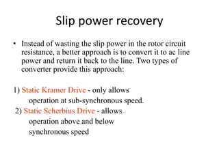
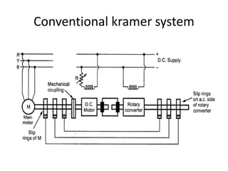
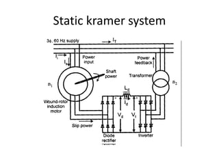
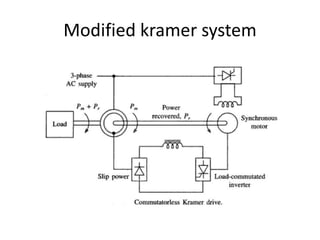
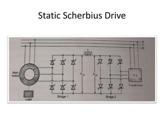
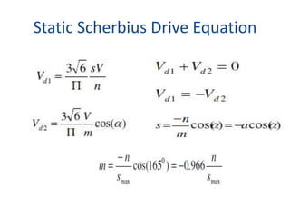
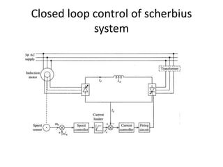


This document discusses slip power recovery in induction motors using static Kramer and Scherbius drives. It provides details on: 1. The conventional Kramer system controls motor speed by injecting a voltage into the rotor circuit at the slip frequency. This allows increasing or decreasing the rotor resistance to control speed. 2. Static Kramer drives only allow sub-synchronous operation while Static Scherbius drives allow both above and below synchronous speeds. 3. Scherbius drives enable bi-directional power flow using positive and negative injected voltages phase with or opposing the rotor current, allowing a wider range of operating conditions than Kramer drives.


