1) Induction generators have the same basic construction as squirrel-cage induction motors but operate at a speed greater than synchronous speed when driven by an external prime mover like a wind turbine or steam turbine.
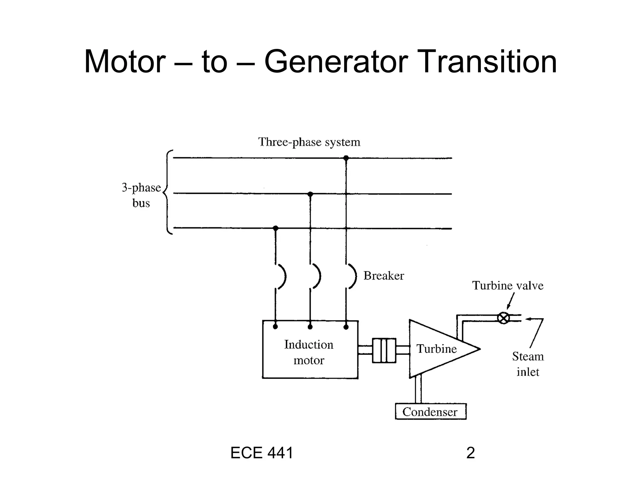
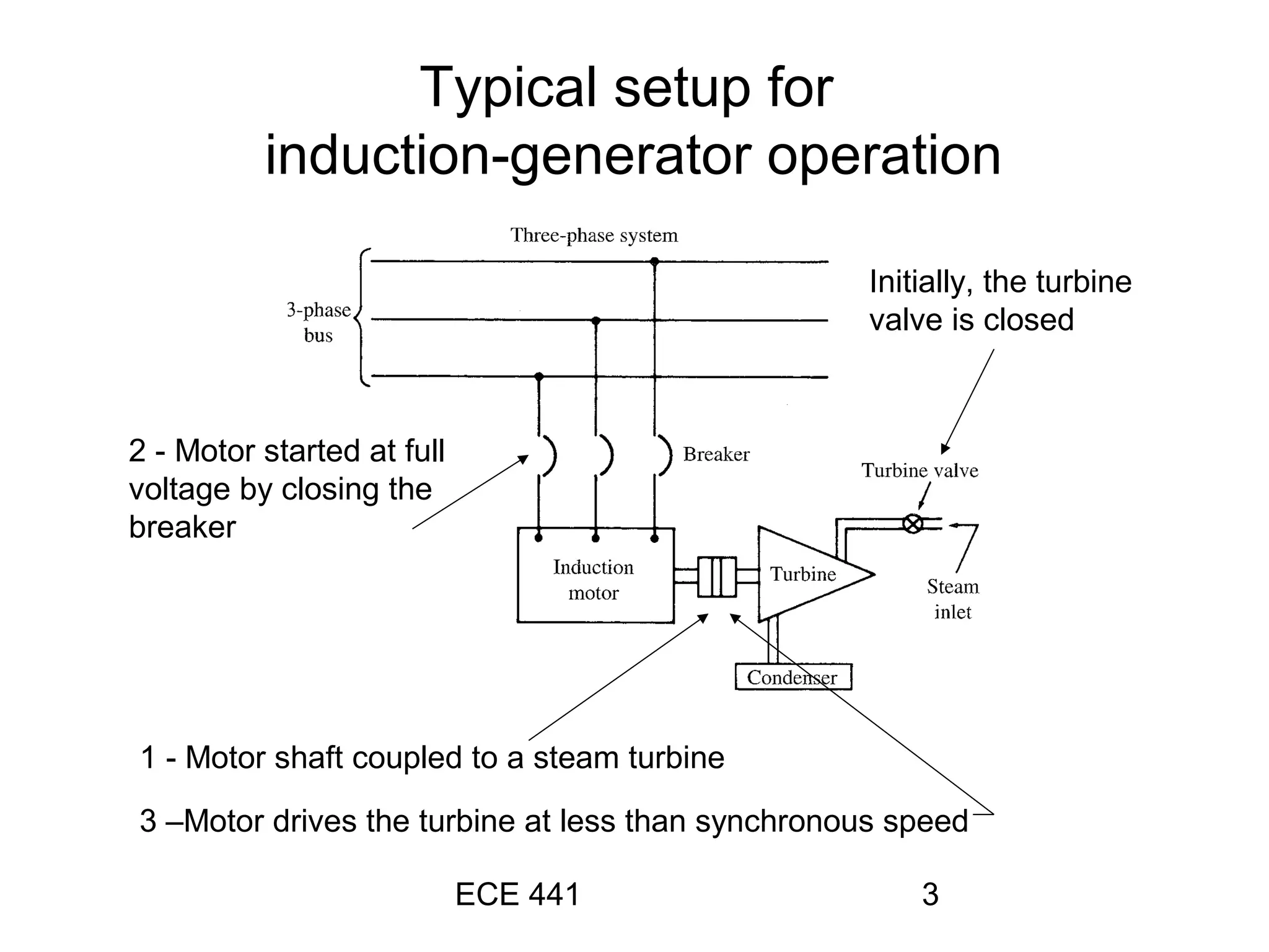
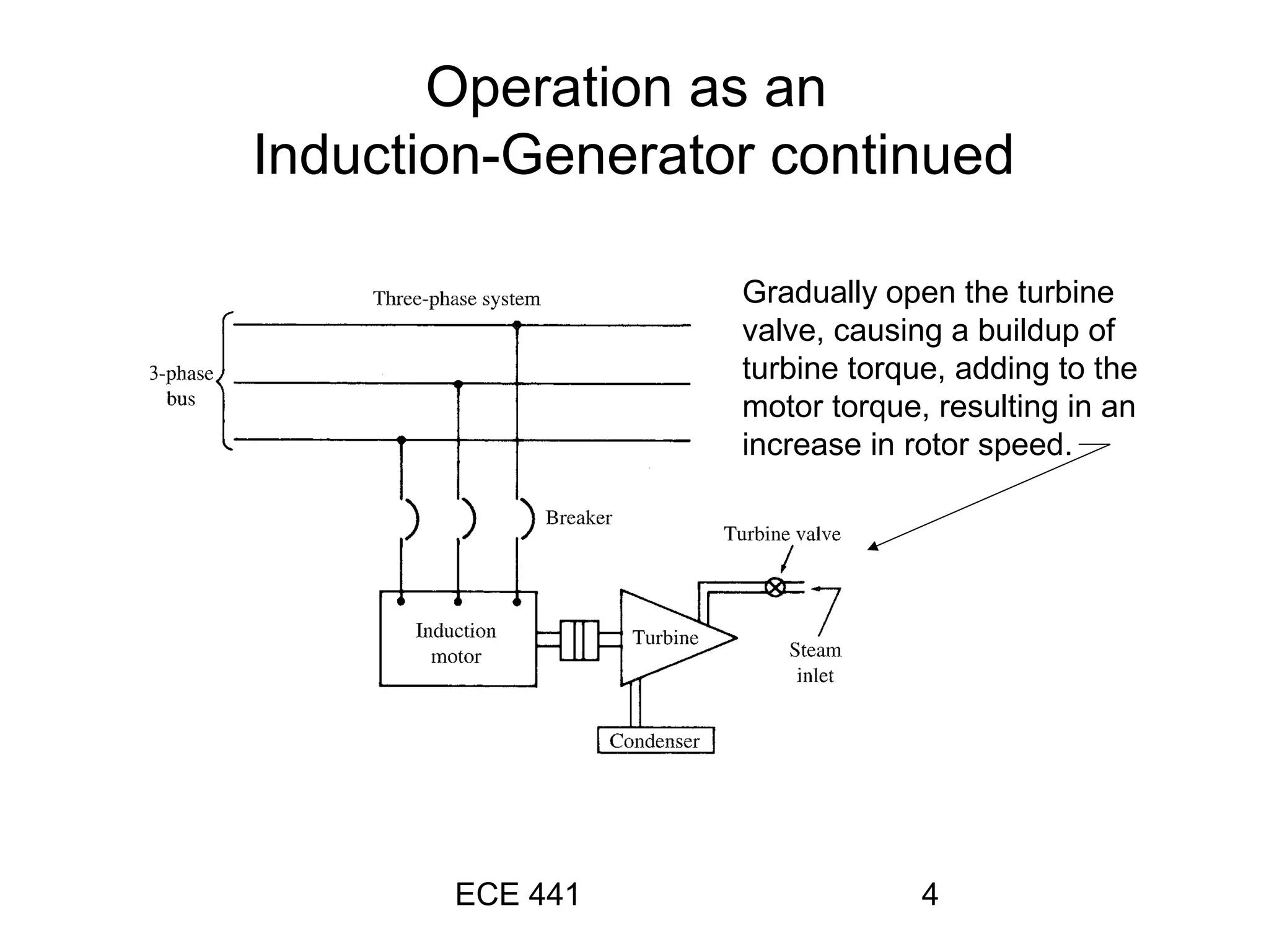
2) To operate an induction motor as a generator, the motor is first started while coupled to a steam turbine that is initially not turning. As the turbine begins to turn, it increases the rotor speed above synchronous speed, causing the motor to act as a generator supplying power to the grid.
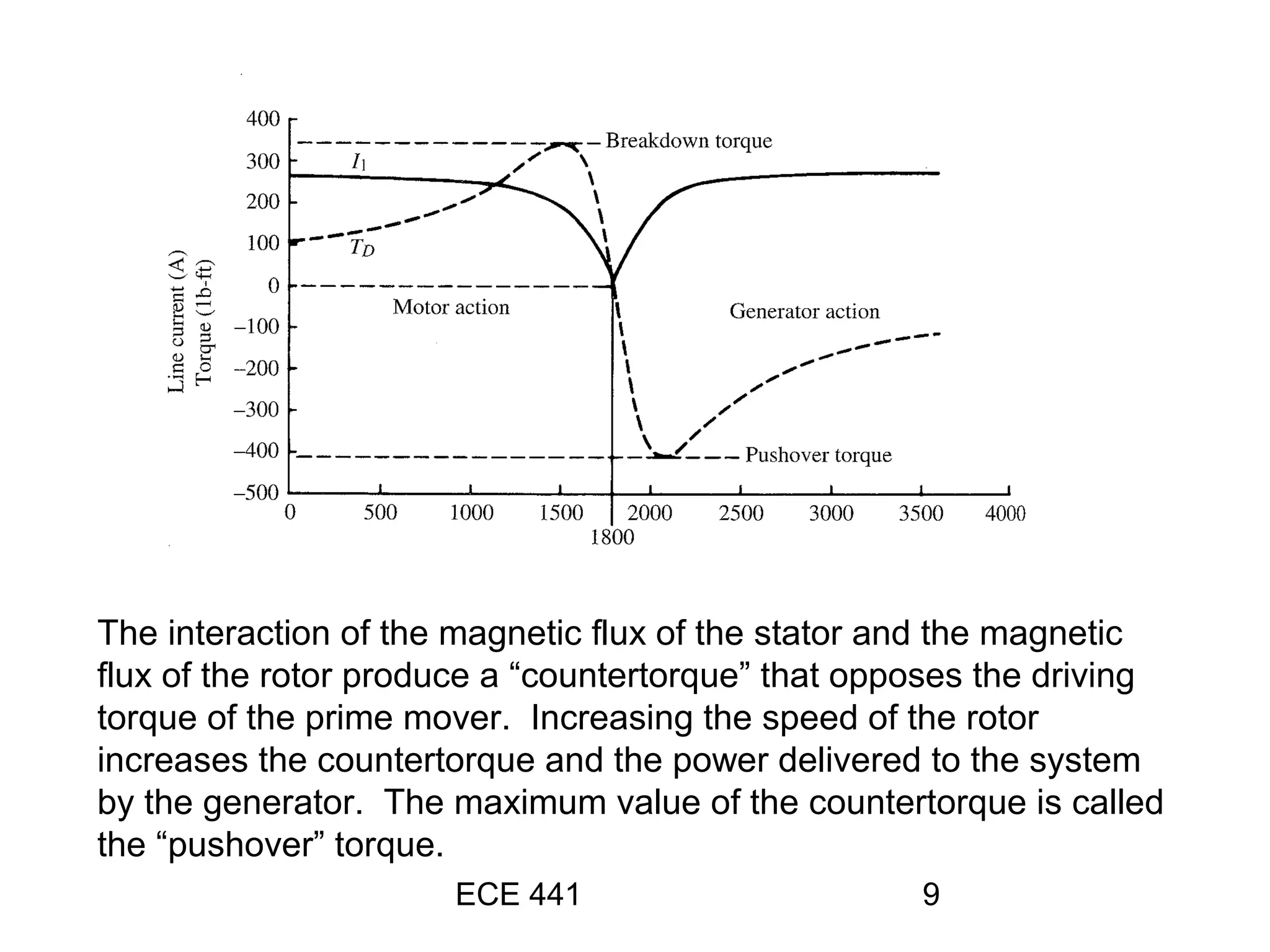
3) In generator mode, the interaction between the stator and rotor magnetic fields produces a countertorque that opposes the driving torque of the prime mover. Increasing rotor speed above synchronous speed increases
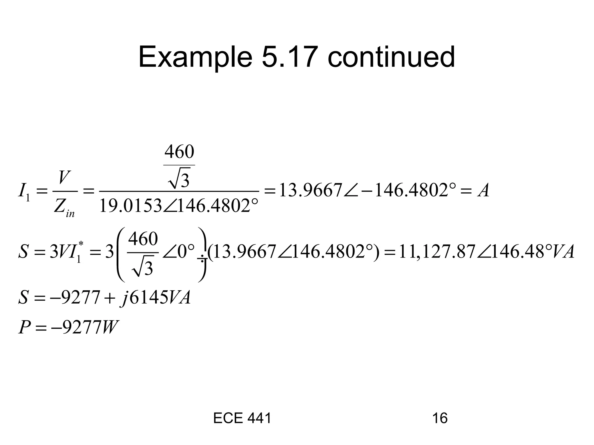
![ECE 441 6
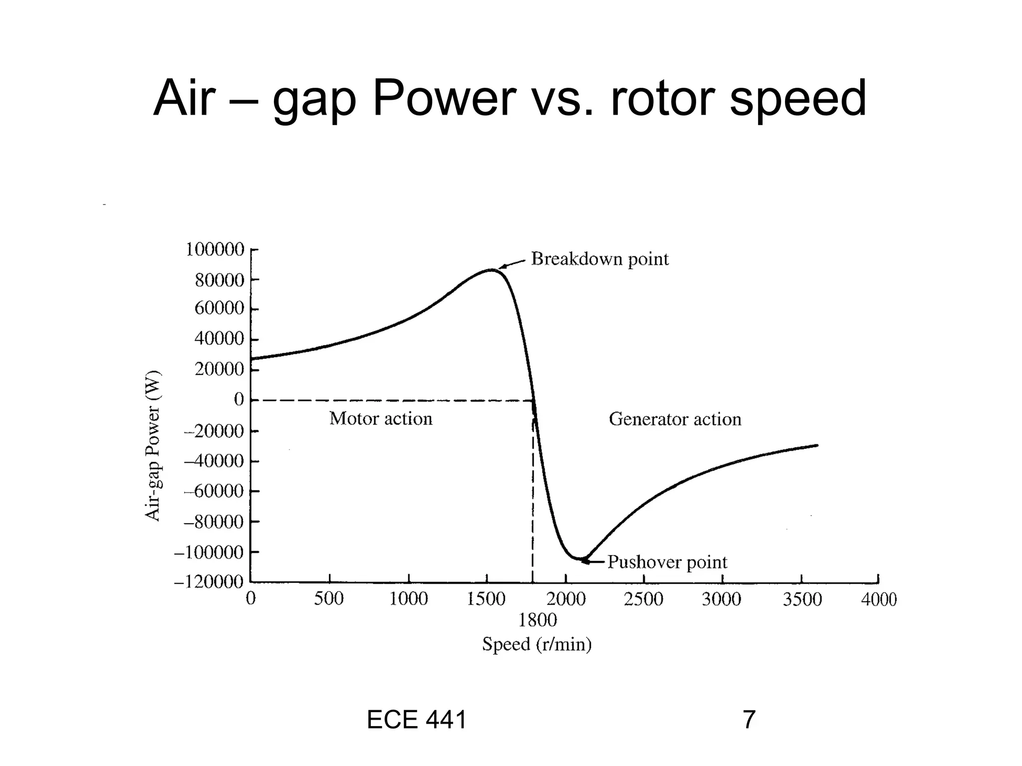
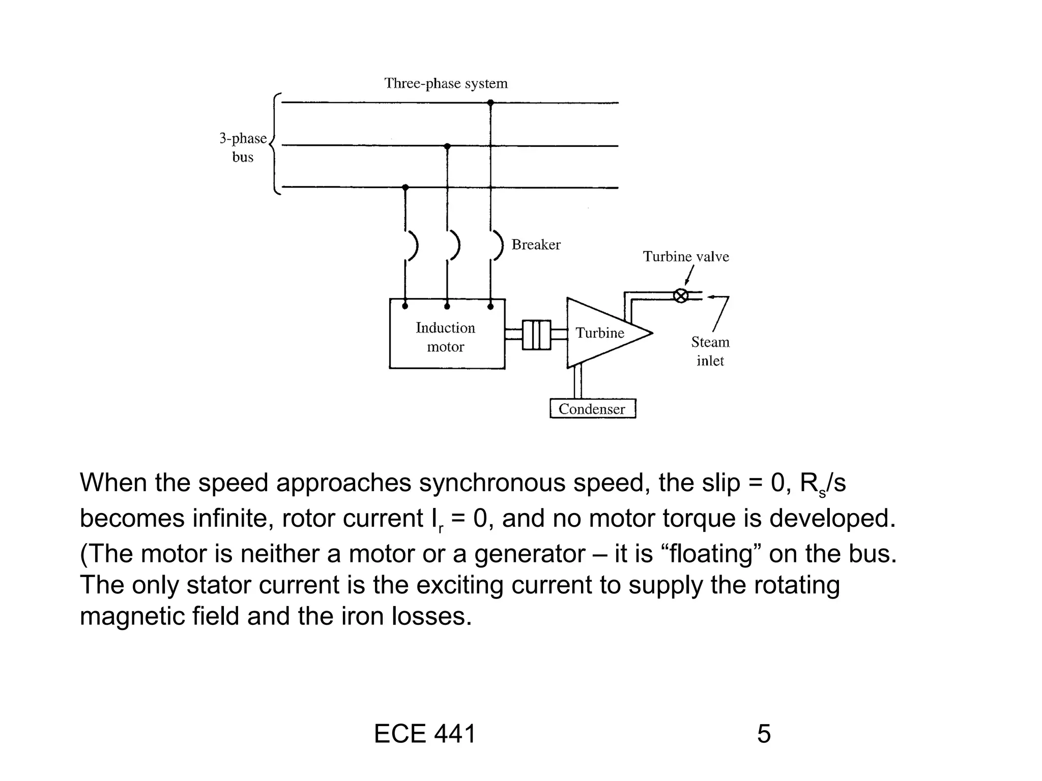
The speed of the rotating flux is independent of the rotor speed –
only a function of the number of poles and the frequency of the
applied voltage. Increasing the rotor speed above the synchronous
speed causes the slip [(ns – nr)/ns] to become negative! The gap
power, Pgap = Prcl/s becomes negative, now supplying power to the
system!](https://image.slidesharecdn.com/3601-160513141823/75/ppt-on-induction-generator-6-2048.jpg)