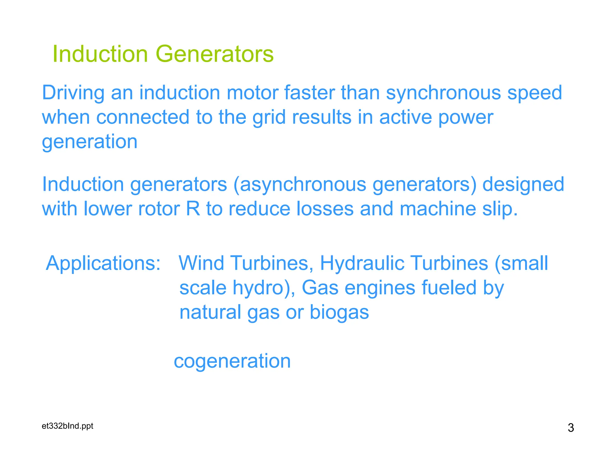
et332bInd.ppt
Lesson 16: Asynchronous
Generators/Induction Generators
ET 332b
Ac Motors, Generators and Power
Systems
1
et332bInd.ppt
Learning Objectives
2
After this presentation you will be able to:
 Explain how an induction generator operates
 List application for induction generators in the use
renewable resources
 Discuss the limitations of induction generators
 Compute the power developed from an induction
generator using the per phase circuit model
et332bInd.ppt 3
Induction Generators
Driving an induction motor faster than synchronous speed
when connected to the grid results in active power
generation
Induction generators (asynchronous generators) designed
with lower rotor R to reduce losses and machine slip.
Applications: Wind Turbines, Hydraulic Turbines (small
scale hydro), Gas engines fueled by
natural gas or biogas
cogeneration
et332bInd.ppt 4
Induction Generator Starting Sequence
Induction
Generator
Breaker
Prime
Mover
Mechanical
Power In
Generator
Losses
Electric
Power
Out
nr >ns
Existing Three Phase System
1.) Breaker open
2.) Increase prime mover
mechanical power input
until nr >ns.
3.) Close Breaker
4.) Adjust mechanical power
input to match electric
load.
Pmech=Pe+Ploss
Induction generator can
not vary terminal voltage
or frequency. Set by
system.
et332bInd.ppt 5
Induction Generator Speed Power Curves
0 500 1000 1500 2000 2500 3000 3500 4000
-100
-50
0
50
100
Induction Machine Speed-Power Curve
Rotor Speed (rpm)
Air
Gap
Power
(kW)
ns
1.1ns
Generator
Operation
Pushover
Power
et332bInd.ppt 6
Limitations of Induction Generations
• Require existing power grid for synchronous
operation.
– Can not control frequency or voltage independently
• Can not operate above pushover speed
• Require a source of reactive power to operate
– When connect to grid, system supplies reactive power
to operate generator
• When operating without grid connection
frequency varies with power output.
– Parallel capacitors supply reactive power
et332bInd.ppt 7
Induction Generator Example
A three-phase, six-pole, 460 V, 60 Hz induction generator operates on
a 480 V system. The generator its rated power output is 20 kW. It
is driven by a turbine at a speed of 1215 rpm. The generator has
the following electrical parameters:
R1 =0.200 W, R2= 0.150 W, Rfe= 320 W,
X1=1.20 W, X2=1.29 W, XM=42.0 W
Find the active power delivered by the generator and the reactive
power it requires from the system to operate.
et332bInd.ppt 8
Example Solution
et332bInd.ppt 9
Example Solution
et332bInd.ppt 10
Example Solution
et332bInd.ppt 11
Example Solution
et332bInd.ppt 12
Isolated Operation of Induction Generators
Induction
Generator
Breaker
Prime
Mover
Mechanical
Power In
Generator
Losses
Electric
Power
Out
nr >ns
Isolated Three Phase System
Reactive
Power from
Capacitors
When nr = ns, no
power delivered
Isolated Induction generator
requires residual flux
to build voltage
Capacitors supply reactive
power to load and
generator when voltage
builds.
Voltage falls rapidly when
load is applied.
et332bInd.ppt 13
Voltage Build-up in Isolated Induction Generators
R1
-jXc
R2/s
jX2
jX1
jXm Rfe
Vin
Current
Voltage
Iop
Vop
Xc0
Xc1
Xc0>Xc1










f
V
I
C
I
V
X
op
op
op
op
c
2
1
External Capacitor provides
Reactive power for operation
Operating point set by intersection
between magnetization curve and
Xc
et332bInd.ppt 14
Voltage Build-up in Isolated Induction Generators
Lab measurements determine the magnetization curve
Three Phase Induction Motor Magnetization Curve
0
20
40
60
80
100
120
140
0.00 0.25 0.50 0.75 1.00 1.25 1.50
Stator Current (A)
Stator
Voltage
(V)
Lab Data Linearized Magnetization Curve Load Line
F
28.45
or
F
10
845
.
2
C
60
2
1
110
1.18
f
2
1
V
I
C
5
op
op





















Inductance
change
due to rotor
motion
et332bInd.ppt 15
Voltage Build-up in Isolated Induction Generators
Single phase motor magnetization curve
Magnetization Curve-Single Phase Motor
0.00
20.00
40.00
60.00
80.00
100.00
120.00
140.00
0.00 1.00 2.00 3.00 4.00 5.00 6.00 7.00
Current (A)
Voltage
(V)
Lab Measurements Linearized Data Load Line
F
127
or
F
10
27
.
1
C
60
2
1
120
5.74
f
2
1
V
I
C
4
op
op




















et332bInd.ppt
END LESSON 16: ASYNCHRONOUS
GENERATORS/INDUCTION
GENERATORS
ET 332b
Ac Motors, Generators and Power Systems
16

Lesson no16 application of Induction Generator in Wind.ppsx

  • 1.
    et332bInd.ppt Lesson 16: Asynchronous Generators/InductionGenerators ET 332b Ac Motors, Generators and Power Systems 1
  • 2.
    et332bInd.ppt Learning Objectives 2 After thispresentation you will be able to:  Explain how an induction generator operates  List application for induction generators in the use renewable resources  Discuss the limitations of induction generators  Compute the power developed from an induction generator using the per phase circuit model
  • 3.
    et332bInd.ppt 3 Induction Generators Drivingan induction motor faster than synchronous speed when connected to the grid results in active power generation Induction generators (asynchronous generators) designed with lower rotor R to reduce losses and machine slip. Applications: Wind Turbines, Hydraulic Turbines (small scale hydro), Gas engines fueled by natural gas or biogas cogeneration
  • 4.
    et332bInd.ppt 4 Induction GeneratorStarting Sequence Induction Generator Breaker Prime Mover Mechanical Power In Generator Losses Electric Power Out nr >ns Existing Three Phase System 1.) Breaker open 2.) Increase prime mover mechanical power input until nr >ns. 3.) Close Breaker 4.) Adjust mechanical power input to match electric load. Pmech=Pe+Ploss Induction generator can not vary terminal voltage or frequency. Set by system.
  • 5.
    et332bInd.ppt 5 Induction GeneratorSpeed Power Curves 0 500 1000 1500 2000 2500 3000 3500 4000 -100 -50 0 50 100 Induction Machine Speed-Power Curve Rotor Speed (rpm) Air Gap Power (kW) ns 1.1ns Generator Operation Pushover Power
  • 6.
    et332bInd.ppt 6 Limitations ofInduction Generations • Require existing power grid for synchronous operation. – Can not control frequency or voltage independently • Can not operate above pushover speed • Require a source of reactive power to operate – When connect to grid, system supplies reactive power to operate generator • When operating without grid connection frequency varies with power output. – Parallel capacitors supply reactive power
  • 7.
    et332bInd.ppt 7 Induction GeneratorExample A three-phase, six-pole, 460 V, 60 Hz induction generator operates on a 480 V system. The generator its rated power output is 20 kW. It is driven by a turbine at a speed of 1215 rpm. The generator has the following electrical parameters: R1 =0.200 W, R2= 0.150 W, Rfe= 320 W, X1=1.20 W, X2=1.29 W, XM=42.0 W Find the active power delivered by the generator and the reactive power it requires from the system to operate.
  • 8.
  • 9.
  • 10.
  • 11.
  • 12.
    et332bInd.ppt 12 Isolated Operationof Induction Generators Induction Generator Breaker Prime Mover Mechanical Power In Generator Losses Electric Power Out nr >ns Isolated Three Phase System Reactive Power from Capacitors When nr = ns, no power delivered Isolated Induction generator requires residual flux to build voltage Capacitors supply reactive power to load and generator when voltage builds. Voltage falls rapidly when load is applied.
  • 13.
    et332bInd.ppt 13 Voltage Build-upin Isolated Induction Generators R1 -jXc R2/s jX2 jX1 jXm Rfe Vin Current Voltage Iop Vop Xc0 Xc1 Xc0>Xc1           f V I C I V X op op op op c 2 1 External Capacitor provides Reactive power for operation Operating point set by intersection between magnetization curve and Xc
  • 14.
    et332bInd.ppt 14 Voltage Build-upin Isolated Induction Generators Lab measurements determine the magnetization curve Three Phase Induction Motor Magnetization Curve 0 20 40 60 80 100 120 140 0.00 0.25 0.50 0.75 1.00 1.25 1.50 Stator Current (A) Stator Voltage (V) Lab Data Linearized Magnetization Curve Load Line F 28.45 or F 10 845 . 2 C 60 2 1 110 1.18 f 2 1 V I C 5 op op                      Inductance change due to rotor motion
  • 15.
    et332bInd.ppt 15 Voltage Build-upin Isolated Induction Generators Single phase motor magnetization curve Magnetization Curve-Single Phase Motor 0.00 20.00 40.00 60.00 80.00 100.00 120.00 140.00 0.00 1.00 2.00 3.00 4.00 5.00 6.00 7.00 Current (A) Voltage (V) Lab Measurements Linearized Data Load Line F 127 or F 10 27 . 1 C 60 2 1 120 5.74 f 2 1 V I C 4 op op                    
  • 16.
    et332bInd.ppt END LESSON 16:ASYNCHRONOUS GENERATORS/INDUCTION GENERATORS ET 332b Ac Motors, Generators and Power Systems 16