Downloaded 141 times


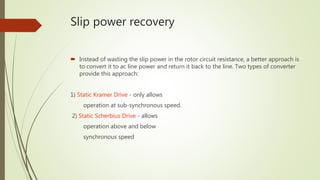
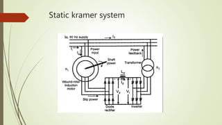
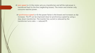
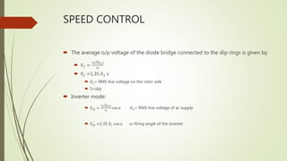
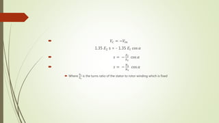
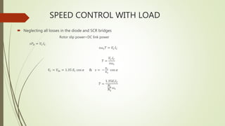
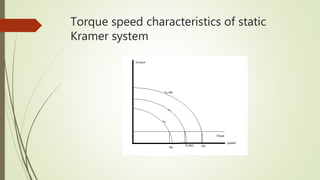


The document discusses the Static Kramer drive system, which allows a motor to operate at sub-synchronous speeds. It does this by converting the slip power in the rotor circuit into AC line power and returning it to the line using an inverter. At zero speed, the motor acts as a transformer and transfers all real power back to the line. Speed is controlled by varying the firing angle of the inverter, which adjusts the rotor slip and synchronous speed. The load torque is directly proportional to the DC link voltage and current, rotor speed, and inversely proportional to the turns ratio between the stator and rotor windings.


![Electric drives [ned mohan 2001 (scanned) 470pág]](https://cdn.slidesharecdn.com/ss_thumbnails/electricdrivesnedmohan2001-scanned470pg-121224050928-phpapp01-thumbnail.jpg?width=640&height=640&fit=bounds)