Downloaded 166 times

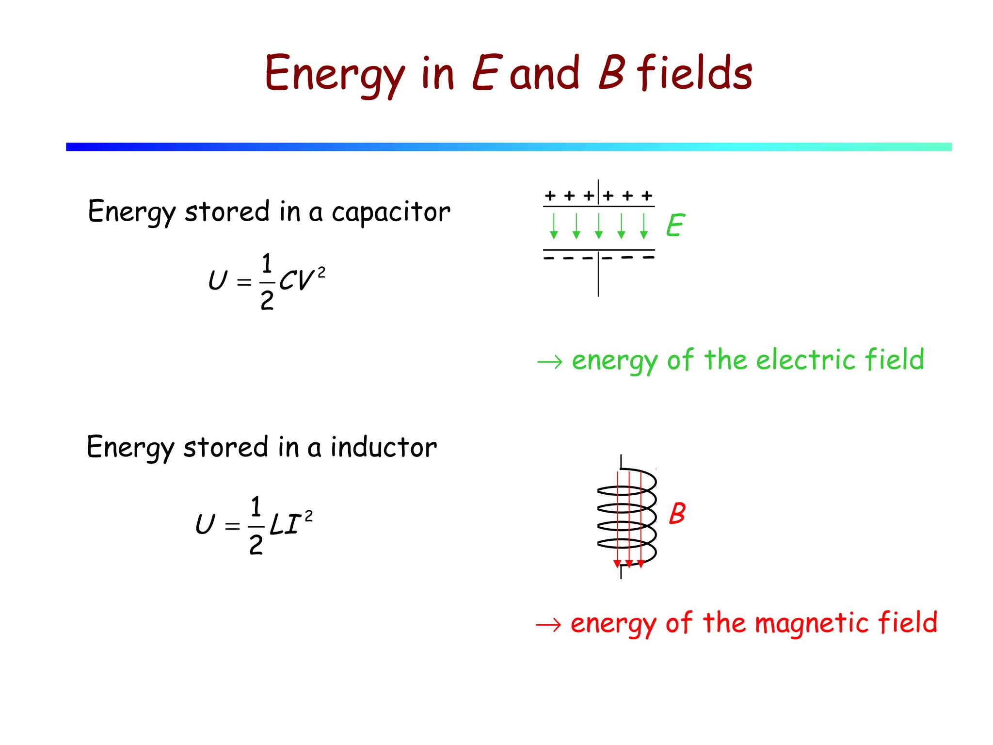
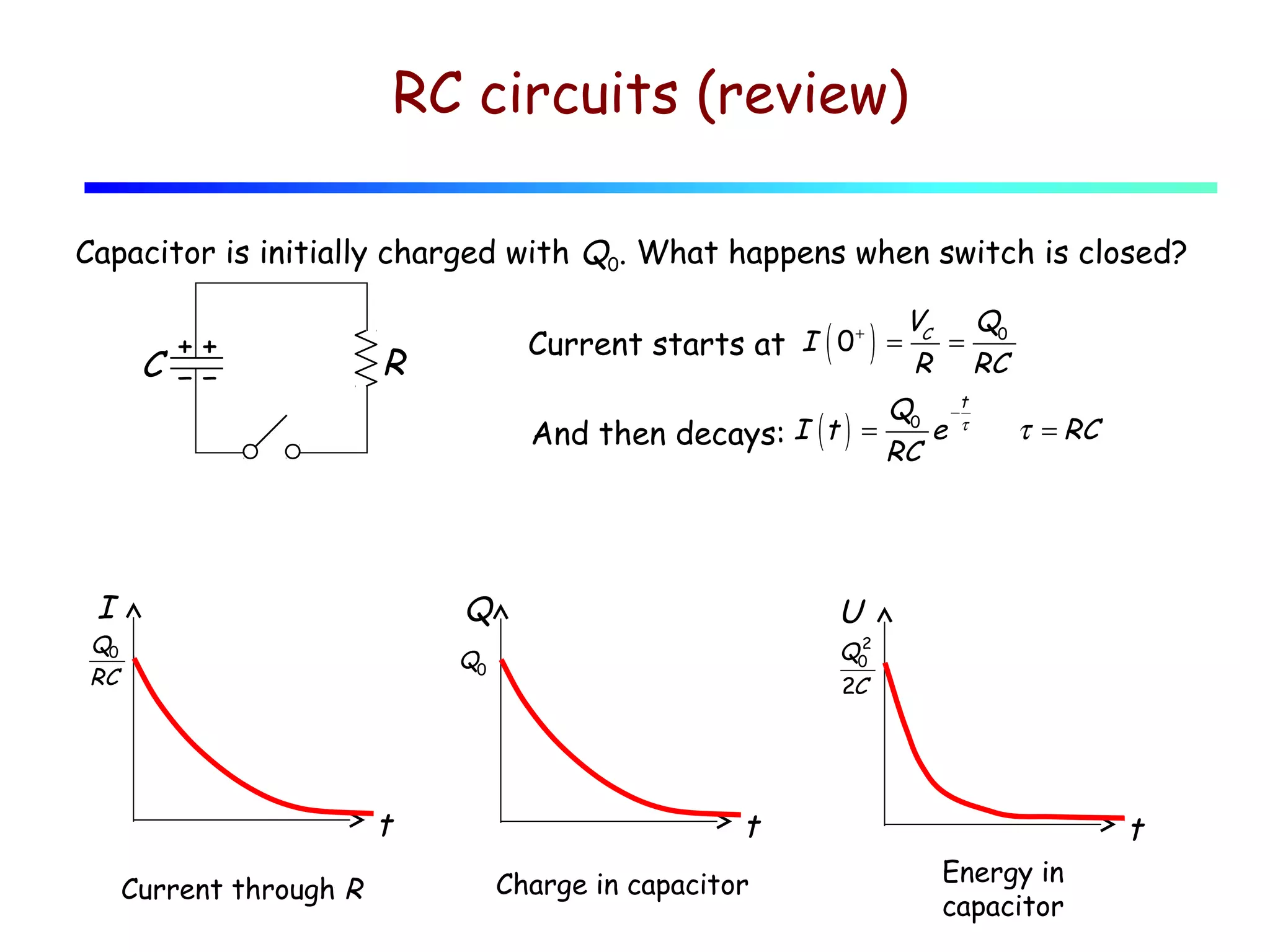

1) This lecture discusses energy storage in capacitors and inductors, as well as RC, RL, LC, and RLC circuits. 2) In an LC circuit without resistance, the charge oscillates back and forth between the capacitor and inductor at the characteristic frequency. 3) When resistance is added to an RLC circuit, the charge still oscillates but decays exponentially over time, governed by the damping ratio.