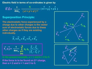
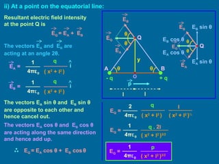
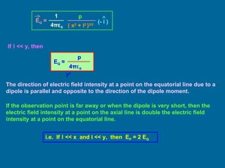
1. The document discusses electric fields created by point charges and electric dipoles. It defines electric field strength and describes how electric field strength is calculated for point charges and dipoles.
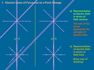
2. Key properties of electric field lines are outlined, including that they emanate from positive charges and terminate at negative charges.
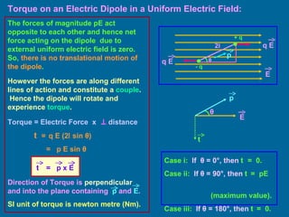
3. Formulas are given for calculating the torque and work done on an electric dipole placed in a uniform electric field. The dipole will experience a torque causing it to rotate into alignment with the field.
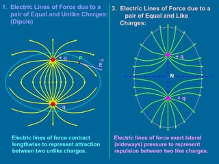
Electrostatic potential and capacitanceEdigniteNGO
Hello everyone, we are from Edignite NGO and we have come up with chapters of class 11 and 12 (CBSE).
For any queries, please contact
Lekha Periwal : +916290889619
Heer Mehta : +917984844099
Describes electrostatic principles and concepts.
**More good stuff available at:
www.wsautter.com
and
http://www.youtube.com/results?search_query=wnsautter&aq=f
This kind of Van de Graaff generator is made up of:
• A motor
• Two rollers
• A belt
• Two brush assemblies
• An output terminal (usually a metal or aluminum sphere)
The strong negative charge from the roller now begins to do two things:
1. It repels the electrons near the tips of the lower brush assembly.
2. It begins to strip nearby air molecules of their electrons.
Applications:
1. It is used to generate x-rays, which is widely used in medicine field.
2. It is used in atom smasher’s, which is used in research purposes.
3. It found applications in physics, medicine, and astro physics.
ANURAG TYAGI CLASSES (ATC) is an organisation destined to orient students into correct path to achieve
success in IIT-JEE, AIEEE, PMT, CBSE & ICSE board classes. The organisation is run by a competitive staff comprising of Ex-IITians. Our goal at ATC is to create an environment that inspires students to recognise and explore their own potentials and build up confidence in themselves.ATC was founded by Mr. ANURAG TYAGI on 19 march, 2001.
based on class 10 chapter electricity.
consists of topic such as-
electric potential,electric current, resistors ,series and parallel connection, heating effect of electric current, electric power,etc.
*Animated PPT FOR SCHOOL/ Coachings *
Physics , Chemistry , maths , biology
(Improve your teaching style )
*CONTENT*:-
1. ANIMATED THEORY
(COMES ON PRESS KEY ONE BY ONE )
2.MCQ
3. LIVE EXAMPLE
4. ANIMATED IMAGES LIKE
SPRING , CAR ETC
5. ANIMATED
6. CHAPTER WISE QUESTIONS AND SOLUTION WITH ANIMATED IMAGES
7. SEPARATE TOPIC SEPARATE FILES
Live example watch this video
https://youtu.be/PG4LTFUKi1A
https://drive.google.com/folderview?id=1KsUPQfeqPQXQ6y6MzoMl07C89yRYhnQt
*Delivery in 1 min in Google drive*
No any file miss .
* Work with in zoom ,Google neet , *
contact/whatsapp:- 9753223223
This Slide explains basic theories in electrostatics, i.e. Coulomb's law, Electric field, electric potential, electric dipole, electric field due to electric dipole, etc.
Visit: https://phystudypoint.blogspot.com
Electric Field Contents 1 Electric Field 3 1.1 Electric Field . 3 1.1.1 Electric Field (Quantitatively Approach) 3 1.1.2 Electric Dipole 6 1.1.3 Electric Field Due To Electric Dipole 6 1.1.4 3-Dimensional Electric Field Problems . 16 1.2 Numerical Computation . 20 1.2.1 Electric Field . 20 1.2.2 Electric Potential . 24 1.3 Displacement Field 26 1.4 Electric Force . 27 1.4.1 Electric Dipole in Electric Field . 27 1.4.2 Oil Drop Experiment . 32 1.5 Charge Density 34 1.6 Motion of Charged Particle in Electric Field 34 1.6.1 Motion of Charge in Uniform Electric Field 34 1.7 Relative Permittivity . 37 1.8 Electric Field Due To Charge Distribution . 37 1.8.1 Charged Rod At Axial Position . 38 1.8.2 Charged Rod On Equatorial Position 39 1.8.3 Charged Rod On Un-Symmetrical Position . 42 1.8.4 Charged Ring At Position On Its Axis . 45 1.8.5 Charged Disk On Its Axis 46 1.8.6 Cavity in a Non-Conducting Sphere . 49 1.9 Electric Force on Surface of Conductor
JEE Main Advanced 12 Sample ebook, which helps you to understand the chapter in easy way also download sample papers and previous year papers and practice to solve the question on time. Download at www.misostudy.com.
JEE Main 12 Sample ebook, which helps you to understand the chapter in easy way also downaload sample papers and previous year papers and practice to solve the question on time. Download at www.misostudy.com.
State of ICS and IoT Cyber Threat Landscape Report 2024 previewPrayukth K V
The IoT and OT threat landscape report has been prepared by the Threat Research Team at Sectrio using data from Sectrio, cyber threat intelligence farming facilities spread across over 85 cities around the world. In addition, Sectrio also runs AI-based advanced threat and payload engagement facilities that serve as sinks to attract and engage sophisticated threat actors, and newer malware including new variants and latent threats that are at an earlier stage of development.
The latest edition of the OT/ICS and IoT security Threat Landscape Report 2024 also covers:
State of global ICS asset and network exposure
Sectoral targets and attacks as well as the cost of ransom
Global APT activity, AI usage, actor and tactic profiles, and implications
Rise in volumes of AI-powered cyberattacks
Major cyber events in 2024
Malware and malicious payload trends
Cyberattack types and targets
Vulnerability exploit attempts on CVEs
Attacks on counties – USA
Expansion of bot farms – how, where, and why
In-depth analysis of the cyber threat landscape across North America, South America, Europe, APAC, and the Middle East
Why are attacks on smart factories rising?
Cyber risk predictions
Axis of attacks – Europe
Systemic attacks in the Middle East
Download the full report from here:
https://sectrio.com/resources/ot-threat-landscape-reports/sectrio-releases-ot-ics-and-iot-security-threat-landscape-report-2024/
Neuro-symbolic is not enough, we need neuro-*semantic*Frank van Harmelen
Neuro-symbolic (NeSy) AI is on the rise. However, simply machine learning on just any symbolic structure is not sufficient to really harvest the gains of NeSy. These will only be gained when the symbolic structures have an actual semantics. I give an operational definition of semantics as “predictable inference”.
All of this illustrated with link prediction over knowledge graphs, but the argument is general.
LF Energy Webinar: Electrical Grid Modelling and Simulation Through PowSyBl -...DanBrown980551
Do you want to learn how to model and simulate an electrical network from scratch in under an hour?
Then welcome to this PowSyBl workshop, hosted by Rte, the French Transmission System Operator (TSO)!
During the webinar, you will discover the PowSyBl ecosystem as well as handle and study an electrical network through an interactive Python notebook.
PowSyBl is an open source project hosted by LF Energy, which offers a comprehensive set of features for electrical grid modelling and simulation. Among other advanced features, PowSyBl provides:
- A fully editable and extendable library for grid component modelling;
- Visualization tools to display your network;
- Grid simulation tools, such as power flows, security analyses (with or without remedial actions) and sensitivity analyses;
The framework is mostly written in Java, with a Python binding so that Python developers can access PowSyBl functionalities as well.
What you will learn during the webinar:
- For beginners: discover PowSyBl's functionalities through a quick general presentation and the notebook, without needing any expert coding skills;
- For advanced developers: master the skills to efficiently apply PowSyBl functionalities to your real-world scenarios.
JMeter webinar - integration with InfluxDB and GrafanaRTTS
Watch this recorded webinar about real-time monitoring of application performance. See how to integrate Apache JMeter, the open-source leader in performance testing, with InfluxDB, the open-source time-series database, and Grafana, the open-source analytics and visualization application.
In this webinar, we will review the benefits of leveraging InfluxDB and Grafana when executing load tests and demonstrate how these tools are used to visualize performance metrics.
Length: 30 minutes
Session Overview
-------------------------------------------
During this webinar, we will cover the following topics while demonstrating the integrations of JMeter, InfluxDB and Grafana:
- What out-of-the-box solutions are available for real-time monitoring JMeter tests?
- What are the benefits of integrating InfluxDB and Grafana into the load testing stack?
- Which features are provided by Grafana?
- Demonstration of InfluxDB and Grafana using a practice web application
To view the webinar recording, go to:
https://www.rttsweb.com/jmeter-integration-webinar
Builder.ai Founder Sachin Dev Duggal's Strategic Approach to Create an Innova...Ramesh Iyer
In today's fast-changing business world, Companies that adapt and embrace new ideas often need help to keep up with the competition. However, fostering a culture of innovation takes much work. It takes vision, leadership and willingness to take risks in the right proportion. Sachin Dev Duggal, co-founder of Builder.ai, has perfected the art of this balance, creating a company culture where creativity and growth are nurtured at each stage.
Dev Dives: Train smarter, not harder – active learning and UiPath LLMs for do...UiPathCommunity
💥 Speed, accuracy, and scaling – discover the superpowers of GenAI in action with UiPath Document Understanding and Communications Mining™:
See how to accelerate model training and optimize model performance with active learning
Learn about the latest enhancements to out-of-the-box document processing – with little to no training required
Get an exclusive demo of the new family of UiPath LLMs – GenAI models specialized for processing different types of documents and messages
This is a hands-on session specifically designed for automation developers and AI enthusiasts seeking to enhance their knowledge in leveraging the latest intelligent document processing capabilities offered by UiPath.
Speakers:
👨🏫 Andras Palfi, Senior Product Manager, UiPath
👩🏫 Lenka Dulovicova, Product Program Manager, UiPath
Essentials of Automations: Optimizing FME Workflows with ParametersSafe Software
Are you looking to streamline your workflows and boost your projects’ efficiency? Do you find yourself searching for ways to add flexibility and control over your FME workflows? If so, you’re in the right place.
Join us for an insightful dive into the world of FME parameters, a critical element in optimizing workflow efficiency. This webinar marks the beginning of our three-part “Essentials of Automation” series. This first webinar is designed to equip you with the knowledge and skills to utilize parameters effectively: enhancing the flexibility, maintainability, and user control of your FME projects.
Here’s what you’ll gain:
- Essentials of FME Parameters: Understand the pivotal role of parameters, including Reader/Writer, Transformer, User, and FME Flow categories. Discover how they are the key to unlocking automation and optimization within your workflows.
- Practical Applications in FME Form: Delve into key user parameter types including choice, connections, and file URLs. Allow users to control how a workflow runs, making your workflows more reusable. Learn to import values and deliver the best user experience for your workflows while enhancing accuracy.
- Optimization Strategies in FME Flow: Explore the creation and strategic deployment of parameters in FME Flow, including the use of deployment and geometry parameters, to maximize workflow efficiency.
- Pro Tips for Success: Gain insights on parameterizing connections and leveraging new features like Conditional Visibility for clarity and simplicity.
We’ll wrap up with a glimpse into future webinars, followed by a Q&A session to address your specific questions surrounding this topic.
Don’t miss this opportunity to elevate your FME expertise and drive your projects to new heights of efficiency.
PHP Frameworks: I want to break free (IPC Berlin 2024)Ralf Eggert
In this presentation, we examine the challenges and limitations of relying too heavily on PHP frameworks in web development. We discuss the history of PHP and its frameworks to understand how this dependence has evolved. The focus will be on providing concrete tips and strategies to reduce reliance on these frameworks, based on real-world examples and practical considerations. The goal is to equip developers with the skills and knowledge to create more flexible and future-proof web applications. We'll explore the importance of maintaining autonomy in a rapidly changing tech landscape and how to make informed decisions in PHP development.
This talk is aimed at encouraging a more independent approach to using PHP frameworks, moving towards a more flexible and future-proof approach to PHP development.
The Art of the Pitch: WordPress Relationships and SalesLaura Byrne
Clients don’t know what they don’t know. What web solutions are right for them? How does WordPress come into the picture? How do you make sure you understand scope and timeline? What do you do if sometime changes?
All these questions and more will be explored as we talk about matching clients’ needs with what your agency offers without pulling teeth or pulling your hair out. Practical tips, and strategies for successful relationship building that leads to closing the deal.
AI for Every Business: Unlocking Your Product's Universal Potential by VP of ...
Electrostatics 2
1.
2. Electric Field: Electric field is a region of space around a charge or a system of charges within which other charged particles experience electrostatic forces. Theoretically, electric field extends upto infinity but practically it is limited to a certain distance. Electric Field Strength or Electric Field Intensity or Electric Field: Electric field strength at a point in an electric field is the electrostatic force per unit positive charge acting on a vanishingly small positive test charge placed at that point. The test charge is considered to be vanishingly small because its presence should not alter the configuration of the charge(s) and thus the electric field which is intended to be measured. or or + q 0 + q 0 + q - q q – Source charge, q 0 – Test charge, F – Force & E - Field E = ∆ q F Lt ∆ q -> 0 q 0 F E = q r 2 1 4 π ε 0 E = r F F
3.
4. Electric Field due to a Point Charge: O Z Y X Force exerted on q 0 by q is P (x,y,z) Electric field strength is or or The electric field due to a point charge has spherical symmetry. If q > 0, then the field is radially outwards. If q < 0, then the field is radially inwards. 0 + q 0 + q F r q q 0 r 2 1 4 π ε 0 r F = q q 0 r 3 1 4 π ε 0 r F = q 0 F E = q r 3 1 4 π ε 0 E (r) = r r 2 1 4 π ε 0 E (r) = q r E r 2
5. Electric field in terms of co-ordinates is given by Superposition Principle: The electrostatic force experienced by a charge due to other charges is the vector sum of electrostatic forces due to these other charges as if they are existing individually. In the present example, a = 1 and b = 2 to 5. If the force is to be found on 2 nd charge, then a = 2 and b = 1 and 3 to 5. ( x 2 + y 2 + z 2 ) 3/2 1 4 π ε 0 E (r) = q i j k ( x + y + z ) + q 2 - q 3 - q 5 + q 4 + q 1 F 12 F 14 F 15 F 13 F 1 = F 12 + F 13 + F 14 + F 15 F 12 F 14 F 15 F 13 F 1 q a q b 1 4 π ε 0 F a (r a ) = ∑ b=1 b ≠a N r a - r b r a - r b │ │ 3
6. Superposition principle holds good for electric field also. Note: The interactions must be on the charge which is to be studied due to other charges. The charge on which the influence due to other charges is to be found is assumed to be floating charge and others are rigidly fixed. For eg. 1 st charge (floating) is repelled away by q 2 and q 4 and attracted towards q 3 and q 5 . The interactions between the other charges (among themselves) must be ignored. i.e. F 23 , F 24 , F 25 , F 34 , F 35 and F 45 are ignored. Electric Lines of Force: An electric line of force is an imaginary straight or curved path along which a unit positive charge is supposed to move when free to do so in an electric field. Electric lines of force do not physically exist but they represent real situations. Electric Lines of Force E E
7.
8.
9.
10.
11.
12. Electric Dipole: Electric dipole is a pair of equal and opposite charges separated by a very small distance. The electric field produced by a dipole is known as dipole field. Electric dipole moment is a vector quantity used to measure the strength of an electric dipole. + q - q The magnitude of electric dipole moment is the product of magnitude of either charge and the distance between the two charges. The direction is from negative to positive charge. The SI unit of ‘p’ is ‘coulomb metre (C m)’. Note: An ideal dipole is the dipole in which the charge becomes larger and larger and the separation becomes smaller and smaller. 2 l p p = ( q x 2 l) l
13. Electric Field Intensity due to an Electric Dipole: i) At a point on the axial line: Resultant electric field intensity at the point P is If l << x, then The direction of electric field intensity at a point on the axial line due to a dipole is always along the direction of the dipole moment. E P = E B - E A + q - q A B E P = E A + E B The vectors E A and E B are collinear and opposite. 1 4 π ε 0 i E A = q (x + l ) 2 q (x - l ) 2 1 4 π ε 0 i E B = │ E P │ = │ E B │ - │ E A │ │ E P │ = q (x + l ) 2 q (x - l ) 2 1 4 π ε 0 ] [ - │ E P │ = 1 4 π ε 0 2 ( q . 2 l ) x (x 2 – l 2 ) 2 │ E P │ = 1 4 π ε 0 2 p x (x 2 – l 2 ) 2 E P ≈ 2 p 4 π ε 0 x 3 l l x P p E A E B O E P = 1 4 π ε 0 2 p x (x 2 – l 2 ) 2 i
14. + q - q A B Resultant electric field intensity at the point Q is ii) At a point on the equatorial line: E A cos θ E B cos θ E B sin θ E A sin θ The vectors E A sin θ and E B sin θ are opposite to each other and hence cancel out. The vectors E A cos θ and E B cos θ are acting along the same direction and hence add up. E Q = E A cos θ + E B cos θ θ θ l l y θ θ p E B E A E Q Q E Q = E A + E B The vectors E A and E B are acting at an angle 2 θ . q ( x 2 + l 2 ) 1 4 π ε 0 E A = i q 1 4 π ε 0 E B = i ( x 2 + l 2 ) E B E A E Q θ θ E Q = q 2 4 π ε 0 ( x 2 + l 2 ) l ( x 2 + l 2 ) ½ 1 E Q = 4 π ε 0 q . 2 l ( x 2 + l 2 ) 3/2 E Q = 1 4 π ε 0 p ( x 2 + l 2 ) 3/2 Q O
15. If l << y, then The direction of electric field intensity at a point on the equatorial line due to a dipole is parallel and opposite to the direction of the dipole moment. If the observation point is far away or when the dipole is very short, then the electric field intensity at a point on the axial line is double the electric field intensity at a point on the equatorial line. i.e. If l << x and l << y, then E P = 2 E Q E Q = 1 4 π ε 0 p ( x 2 + l 2 ) 3/2 (- i ) E Q ≈ p 4 π ε 0 y 3
16. Torque on an Electric Dipole in a Uniform Electric Field: The forces of magnitude pE act opposite to each other and hence net force acting on the dipole due to external uniform electric field is zero. So, there is no translational motion of the dipole . However the forces are along different lines of action and constitute a couple . Hence the dipole will rotate and experience torque . t = q E (2 l sin θ ) = p E sin θ + q - q 2 l Case i: If θ = 0 ° , then t = 0. Case ii: If θ = 90 ° , then t = pE (maximum value). Case iii: If θ = 180°, then t = 0. θ Torque = Electric Force x distance θ q E q E E t p E Direction of Torque is perpendicular and into the plane containing p and E . SI unit of torque is newton metre (Nm). t = p x E p
17. Work done on an Electric Dipole in Uniform Electric Field: dW = t d θ = p E sin θ d θ W = ∫ p E sin θ d θ W = p E (cos θ 1 - cos θ 2 ) If Potential Energy is arbitrarily taken zero when the dipole is at 90 °, then P.E in rotating the dipole and inclining it at an angle θ is Potential Energy U = - p E cos θ Note: Potential Energy can be taken zero arbitrarily at any position of the dipole. - q 2 l + q When an electric dipole is placed in a uniform electric field, it experiences torque and tends to allign in such a way to attain stable equilibrium. Case i: If θ = 0 ° , then U = - pE (Stable Equilibrium) Case ii: If θ = 90 ° , then U = 0 Case iii: If θ = 180°, then U = pE (Unstable Equilibrium) END θ 1 θ 2 q E E θ 1 θ 2 q E q E q E d θ