Downloaded 391 times
![A circuit containing a series combination of a resistor and a
capacitor is called an RC circuit.
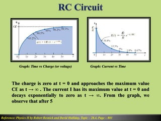
Maximum current of the circuit, I0 =
Ɛ
𝐑
[When, t = 0, Maximum
current flows]
Maximum Charge on Capacitor, Q = CƐ [When t = tf = 5τ]
Reference: Physics II by Robert Resnick and David Halliday, Topic – 28.4, Page – 883](https://image.slidesharecdn.com/1-150221115805-conversion-gate02/85/1-rc-rl-rlc-3-320.jpg)

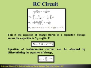


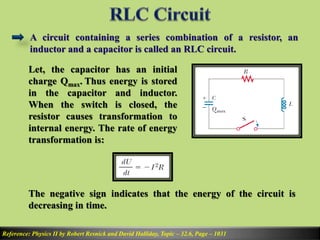


1) An RC circuit contains a resistor and capacitor in series. The charge on the capacitor and current through the circuit can be expressed as exponential functions of time, with the time constant τ=RC. 2) For an RL circuit, the current through the inductor is expressed as 1-e^(-t/τ) where τ=L/R. This shows the current rising exponentially towards its maximum value. 3) In an RLC circuit, the charge on the capacitor undergoes damped harmonic oscillations expressed as e^(-Rt/2L)cos(ωdt), where ωd is the angular frequency of oscillations.