Downloaded 1,921 times


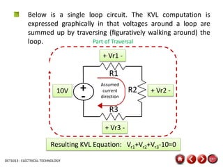


The document discusses Kirchhoff's laws, which are two fundamental laws of circuit analysis: 1) Kirchhoff's voltage law (KVL) states that the sum of the voltages around any closed loop is equal to zero. 2) Kirchhoff's current law (KCL) states that the algebraic sum of the currents entering and leaving any node in a circuit is equal to zero. The document provides examples of applying KVL and KCL to analyze circuits and solve for unknown voltages and currents. It also includes a quiz on Kirchhoff's laws.