https://academics.boun.edu.tr/sema.dumanli/
https://bountenna.boun.edu.tr/
EE101, Lecture 4: Alternating Current and
Components
Assoc. Prof. Sema Dumanlı Oktar
Outline
• AC Fundamentals
• Capacitors and Inductors
• RC Circuits
• Transformers
Re: Direct and Alternative Current
DC:
• Flow of electric charge that
occurs in one direction
• Typically produced by
batteries and direct current
generator
• Not economically feasible to
transmit because of high
voltages needed for long-
distance transmission
AC:
• Alternating currents flow
back and forth.
• AC is preferred over DC due
to their ease of generation
and distribution.
Alternating Currents
• DC
• AC
AC Voltages
• If we pass an alternating current through a
resistor, we can observe across the resistor an
AC voltage whose instantaneous value obeys
Ohm’s law.
• This voltage can be written as
• Vp is the peak value, w is the angular frequency
(rad/s), and t is time.
v t
( ) =Vp sinwt
AC Voltages
• Note that
• f is the frequency in Hz.
• What about the power?
w = 2pf
AC Voltages
-2.5
-2
-1.5
-1
-0.5
0
0.5
1
1.5
2
2.5
0 0.5 1 1.5 2 2.5
I
V
P
AC Voltages
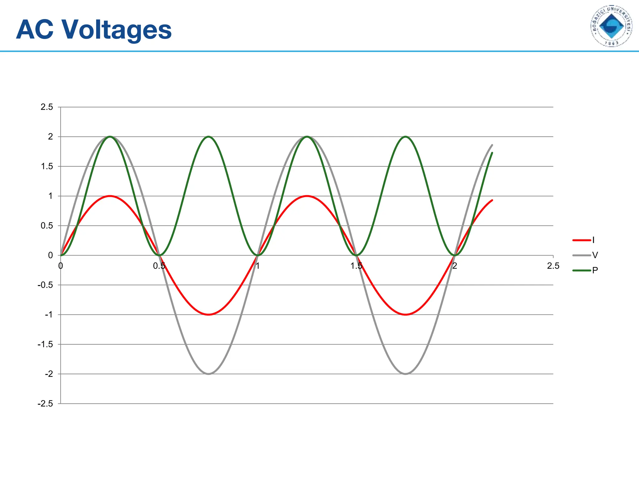
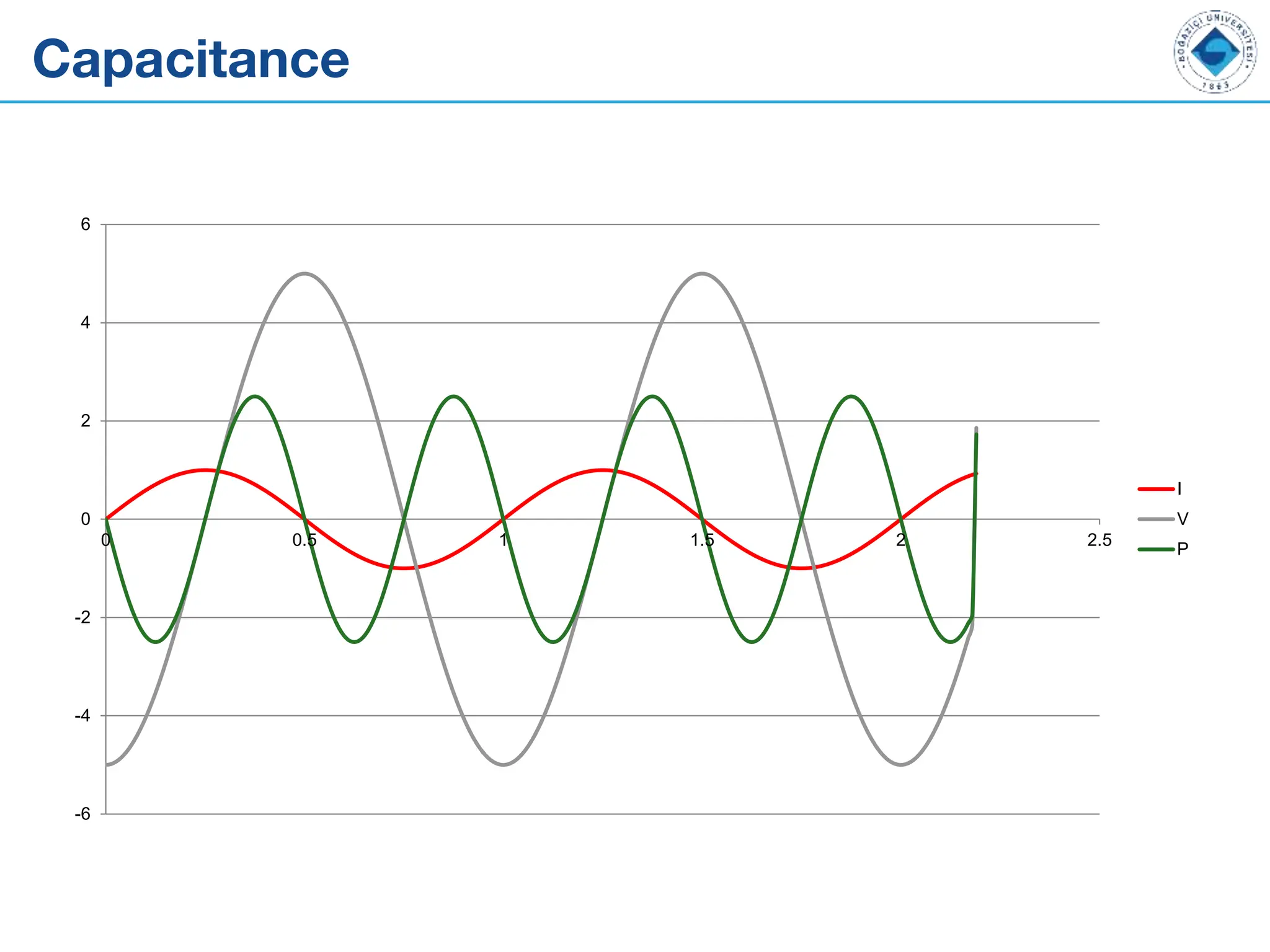
• Let us solve for the power
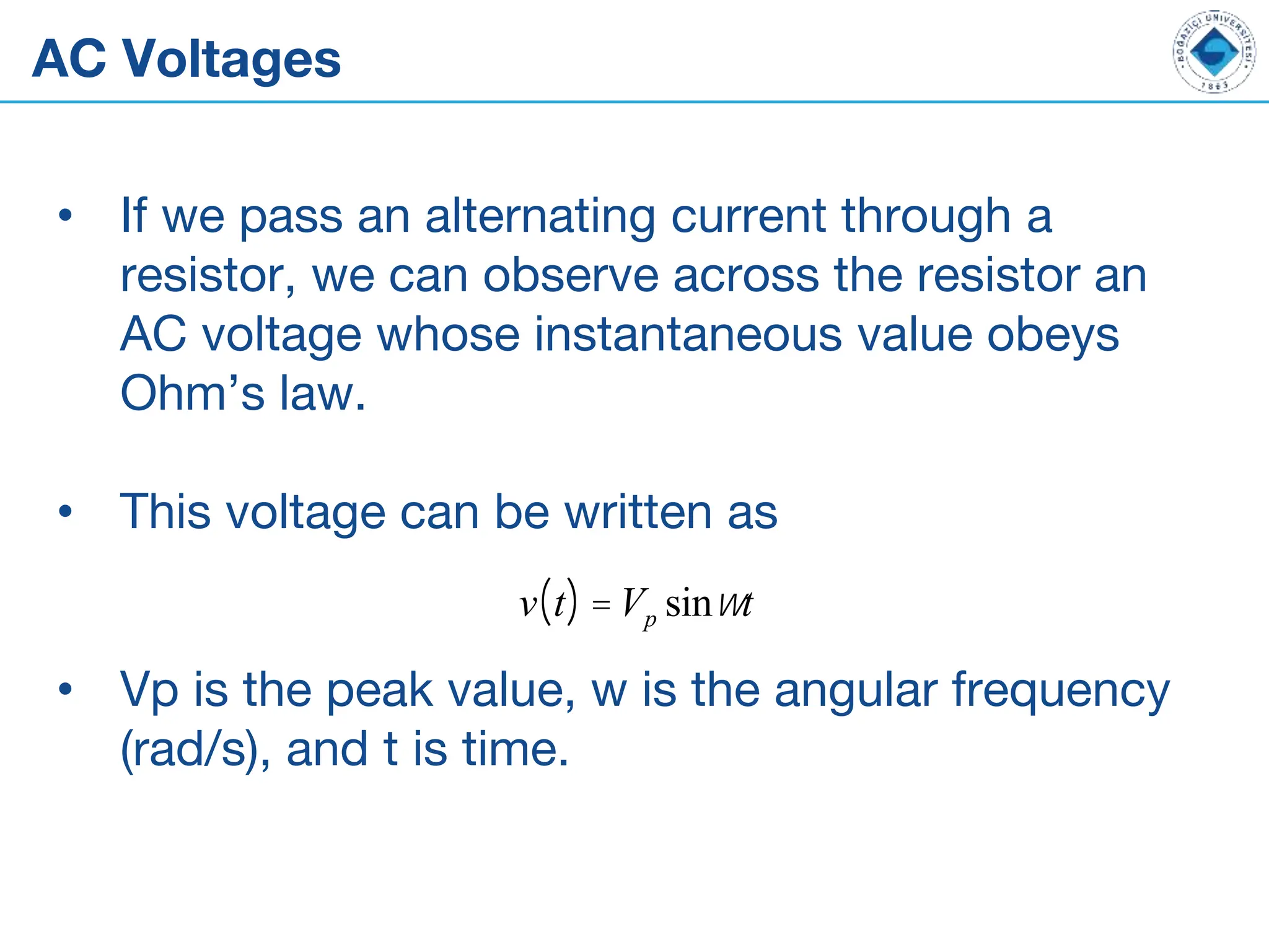
V = Vp sinwt
I =
Vp
R
sinwt
P = VI =
Vp
2
R
sin2
wt =
Vp
2
2R
1- cos 2wt
( )
[ ]
Pave =
Vp
2
2R
º
Vrms
2
R
Vrms º
Vp
2
Capacitors
• If we align two conductive plates parallel to
each other, separate them with an insulator, we
have formed a capacitor.
• Capacitors store charge.
• The variable C is used to denote capacitance
and the unit is Farads.
Q = CV
Capacitors
Capacitance
• Using the definition of current
• For a parallel plate capacitor,
• ∈0 is the dielectric constant of free air and is 8.85 X 10⁻¹² F/m.
I =
dQ
dt
= C
dV
dt
C =
ere0A
d
Capacitance
-6
-4
-2
0
2
4
6
0 0.5 1 1.5 2 2.5
I
V
P
Real Capacitors
Capacitance
• ∈0 is the relative dielectric constant
Material Relative Dielectric
Constant
Dielectric Strength
(kV/cm)
Vacuum 1.00000 ∞
Air 1.00054 8
Paper 3.5 140
Polystyrene 2.6 250
Teflon 2.1 600
Titanium Dioxide 100 60
Capacitance
• The overall power dissipation over time is zero.
• Capacitors do not dissipate power, they store
energy when charging and return it to the
circuit when discharging.
• The energy stored in a capacitor is given by
U =
1
2
CV 2
Capacitor-Water Analogy
• “Charging a capacitor is analogous to filling up a glass with
water:”
A. Sheikholeslami, "A Capacitor Analogy, Part 1 [Circuit Intuitions]," in IEEE Solid-State Circuits Magazine, vol. 8, no.
3, pp. 7-91, Summer 2016. http://ieeexplore.ieee.org/stamp/stamp.jsp?tp=&arnumber=7559992&isnumber=7559939
Capacitor-Water Analogy
• “The water dropped initially into the glass
wastes all of its potential energy. As the water
height increases, the newly added water keeps
more of its potential energy in the glass and
wastes less.”
A. Sheikholeslami, "A Capacitor Analogy, Part 1 [Circuit Intuitions]," in IEEE Solid-State Circuits Magazine, vol. 8, no.
3, pp. 7-91, Summer 2016. http://ieeexplore.ieee.org/stamp/stamp.jsp?tp=&arnumber=7559992&isnumber=7559939
RC Circuits
• Imagine the circuit below with the capacitor
charged to V0.
C R
RC Circuits
• What will the voltage across the capacitor
look like?
• It will start from V0.
• It will decrease until all the charge is
dissipated and will drop to 0 V.
• As the current is flowing, an opposite
voltage will appear across the resistor,
slowing down the discharge.
RC Circuits
• We can write the following equations:
• The voltage is a function whose derivative is
similar to itself.
• What can this function be?
• An exponential!!!
C
dV
dt
= I = -
V
R
dV
dt
= -
1
RC
V º -
1
t
V
RC Circuits
• Thus, V(t) turns out to be
• V0 is the initial voltage, whereas 𝜏 is called the
time constant and is given by 𝜏=RC.
• C determines how much charge is stored,and
R determines how fast it is dissipated.
• Their product determines the rate of decay.
V(t) =V0e
- t
t
RC Circuits
RC Circuits
• This function is called the exponential
decay.
• It is very common in many natural
processes:
• Radioactive decay
• Newton’s law of cooling
• Chemical reaction rates depending on
concentration of reactant.
• …
RC Circuits
• Now, let us take the following circuit
+
-
V
DC:5V
R
C
RC Circuits
• What does the voltage across the
capacitor look like?
• We expect the capacitor to charge to the
value of the voltage source.
• We expect that it charges fast in the
beginning, slowing down as the capacitor
voltage increases.
RC Circuits
• We can write the following equations:
-VS +VR +VC = 0
-VS + IR +VC = 0
I = C
dVC
dt
VC t
( ) = VS 1- e
- t
t
( )
RC Circuits
RC Circuits
• Universal voltage and current curves for
RC circuit
RC Circuits
• What if the input were a pulse?
• The capacitor would repeatedly charge and
discharge.
RC Circuits
Inductance
• When an electric current passes through an
inductor, it creates a magnetic field.
• Energy is stored in space around the inductor
as magnetic field builds up.
• This opposes any change in current.
• It is like momentum or inertia.
• In our water model, it is like a heavy paddle
wheel placed in the current.
Inductance
• We can write the following equation for
inductance:
V = L
di
dt
Inductance
Transformers
• When two or more inductors share a common
magnetic core, the resulting device is a
transformer.
• When an AC voltage is applied to one of the
windings of the transformer, it will create a
magnetic field proportional to the number of
turns.
• This magnetic field will be coupled to the next
winding, creating an AC voltage depending on
its number of turns.
Transformers
• Therefore,
V1
V2
=
N1
N2
Transformers
• Since an ideal transformer cannot create or
dissipate power,
P =V1I1 =V2I2
Transformers
Electrical Quantites
Quantity Variable Unit Unit
Symbol
Typical
Values
Defining
Relations
Important
Equations
Charge Q Coulomb C 10-18 – 1 Mag of
6.24X10⁻¹⁸
charges
I = dq/dt
Current I Ampere A 10-6 – 103 1A = 1C/s KCL
Voltage V Volt V 10-6 – 106 1V=1N-m/C KVL
Power P Watt W 10-6 – 106 1W = 1J/s P = IV
Energy U Joule J 10-15 – 1012 1J = 1N-m U = QV
Force F Newton N 1N=1kg-m/s2
Time t Second s
Resistance R Ohm W 1 – 107 V = IR
Capacitance C Farad F 10-15 – 10 Q = CV
Inductance L Henry H 10-6 – 1 V = L di/dt
Next Lecture
• Introduction to Semiconductors
• Rules and Regulations

EE101 Lecture 4 Updated Electronics engineering

  • 1.
    https://academics.boun.edu.tr/sema.dumanli/ https://bountenna.boun.edu.tr/ EE101, Lecture 4:Alternating Current and Components Assoc. Prof. Sema Dumanlı Oktar
  • 2.
    Outline • AC Fundamentals •Capacitors and Inductors • RC Circuits • Transformers
  • 3.
    Re: Direct andAlternative Current DC: • Flow of electric charge that occurs in one direction • Typically produced by batteries and direct current generator • Not economically feasible to transmit because of high voltages needed for long- distance transmission AC: • Alternating currents flow back and forth. • AC is preferred over DC due to their ease of generation and distribution.
  • 4.
  • 5.
    AC Voltages • Ifwe pass an alternating current through a resistor, we can observe across the resistor an AC voltage whose instantaneous value obeys Ohm’s law. • This voltage can be written as • Vp is the peak value, w is the angular frequency (rad/s), and t is time. v t ( ) =Vp sinwt
  • 6.
    AC Voltages • Notethat • f is the frequency in Hz. • What about the power? w = 2pf
  • 7.
  • 8.
    AC Voltages • Letus solve for the power V = Vp sinwt I = Vp R sinwt P = VI = Vp 2 R sin2 wt = Vp 2 2R 1- cos 2wt ( ) [ ] Pave = Vp 2 2R º Vrms 2 R Vrms º Vp 2
  • 9.
    Capacitors • If wealign two conductive plates parallel to each other, separate them with an insulator, we have formed a capacitor. • Capacitors store charge. • The variable C is used to denote capacitance and the unit is Farads. Q = CV
  • 10.
  • 11.
    Capacitance • Using thedefinition of current • For a parallel plate capacitor, • ∈0 is the dielectric constant of free air and is 8.85 X 10⁻¹² F/m. I = dQ dt = C dV dt C = ere0A d
  • 12.
  • 13.
  • 14.
    Capacitance • ∈0 isthe relative dielectric constant Material Relative Dielectric Constant Dielectric Strength (kV/cm) Vacuum 1.00000 ∞ Air 1.00054 8 Paper 3.5 140 Polystyrene 2.6 250 Teflon 2.1 600 Titanium Dioxide 100 60
  • 15.
    Capacitance • The overallpower dissipation over time is zero. • Capacitors do not dissipate power, they store energy when charging and return it to the circuit when discharging. • The energy stored in a capacitor is given by U = 1 2 CV 2
  • 16.
    Capacitor-Water Analogy • “Charginga capacitor is analogous to filling up a glass with water:” A. Sheikholeslami, "A Capacitor Analogy, Part 1 [Circuit Intuitions]," in IEEE Solid-State Circuits Magazine, vol. 8, no. 3, pp. 7-91, Summer 2016. http://ieeexplore.ieee.org/stamp/stamp.jsp?tp=&arnumber=7559992&isnumber=7559939
  • 17.
    Capacitor-Water Analogy • “Thewater dropped initially into the glass wastes all of its potential energy. As the water height increases, the newly added water keeps more of its potential energy in the glass and wastes less.” A. Sheikholeslami, "A Capacitor Analogy, Part 1 [Circuit Intuitions]," in IEEE Solid-State Circuits Magazine, vol. 8, no. 3, pp. 7-91, Summer 2016. http://ieeexplore.ieee.org/stamp/stamp.jsp?tp=&arnumber=7559992&isnumber=7559939
  • 18.
    RC Circuits • Imaginethe circuit below with the capacitor charged to V0. C R
  • 19.
    RC Circuits • Whatwill the voltage across the capacitor look like? • It will start from V0. • It will decrease until all the charge is dissipated and will drop to 0 V. • As the current is flowing, an opposite voltage will appear across the resistor, slowing down the discharge.
  • 20.
    RC Circuits • Wecan write the following equations: • The voltage is a function whose derivative is similar to itself. • What can this function be? • An exponential!!! C dV dt = I = - V R dV dt = - 1 RC V º - 1 t V
  • 21.
    RC Circuits • Thus,V(t) turns out to be • V0 is the initial voltage, whereas 𝜏 is called the time constant and is given by 𝜏=RC. • C determines how much charge is stored,and R determines how fast it is dissipated. • Their product determines the rate of decay. V(t) =V0e - t t
  • 22.
  • 23.
    RC Circuits • Thisfunction is called the exponential decay. • It is very common in many natural processes: • Radioactive decay • Newton’s law of cooling • Chemical reaction rates depending on concentration of reactant. • …
  • 24.
    RC Circuits • Now,let us take the following circuit + - V DC:5V R C
  • 25.
    RC Circuits • Whatdoes the voltage across the capacitor look like? • We expect the capacitor to charge to the value of the voltage source. • We expect that it charges fast in the beginning, slowing down as the capacitor voltage increases.
  • 26.
    RC Circuits • Wecan write the following equations: -VS +VR +VC = 0 -VS + IR +VC = 0 I = C dVC dt VC t ( ) = VS 1- e - t t ( )
  • 27.
  • 28.
    RC Circuits • Universalvoltage and current curves for RC circuit
  • 29.
    RC Circuits • Whatif the input were a pulse? • The capacitor would repeatedly charge and discharge.
  • 30.
  • 31.
    Inductance • When anelectric current passes through an inductor, it creates a magnetic field. • Energy is stored in space around the inductor as magnetic field builds up. • This opposes any change in current. • It is like momentum or inertia. • In our water model, it is like a heavy paddle wheel placed in the current.
  • 32.
    Inductance • We canwrite the following equation for inductance: V = L di dt
  • 33.
  • 34.
    Transformers • When twoor more inductors share a common magnetic core, the resulting device is a transformer. • When an AC voltage is applied to one of the windings of the transformer, it will create a magnetic field proportional to the number of turns. • This magnetic field will be coupled to the next winding, creating an AC voltage depending on its number of turns.
  • 35.
  • 36.
    Transformers • Since anideal transformer cannot create or dissipate power, P =V1I1 =V2I2
  • 37.
  • 38.
    Electrical Quantites Quantity VariableUnit Unit Symbol Typical Values Defining Relations Important Equations Charge Q Coulomb C 10-18 – 1 Mag of 6.24X10⁻¹⁸ charges I = dq/dt Current I Ampere A 10-6 – 103 1A = 1C/s KCL Voltage V Volt V 10-6 – 106 1V=1N-m/C KVL Power P Watt W 10-6 – 106 1W = 1J/s P = IV Energy U Joule J 10-15 – 1012 1J = 1N-m U = QV Force F Newton N 1N=1kg-m/s2 Time t Second s Resistance R Ohm W 1 – 107 V = IR Capacitance C Farad F 10-15 – 10 Q = CV Inductance L Henry H 10-6 – 1 V = L di/dt
  • 39.
    Next Lecture • Introductionto Semiconductors • Rules and Regulations