December 5, 2007
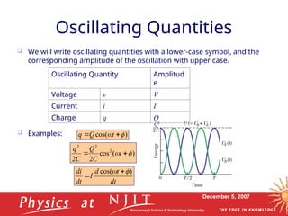
OscillatingQuantities
We will write oscillating quantities with a lower-case symbol, and the
corresponding amplitude of the oscillation with upper case.
Examples:
Oscillating Quantity Amplitud
e
Voltage v V
Current i I
Charge q Q
)
cos(
t
Q
q
)
(
cos
2
2
2
2
2
t
C
Q
C
q
dt
t
d
I
dt
di )
cos(
4.
December 5, 2007
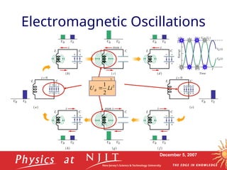
Derivationof Oscillation
Frequency
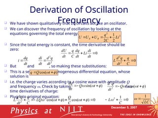
We have shown qualitatively that LC circuits act like an oscillator.
We can discover the frequency of oscillation by looking at the
equations governing the total energy.
Since the total energy is constant, the time derivative should be
zero:
But and , so making these substitutions:
This is a second-order, homogeneous differential equation, whose
solution is
i.e. the charge varies according to a cosine wave with amplitude Q
and frequency . Check by taking two
time derivatives of charge:
Plug into original equation:
2
2
2
1
2
Li
C
q
U
U
U B
E
0
dt
di
Li
dt
dq
C
q
dt
dU
dt
dq
i 2
2
dt
q
d
dt
di
0
2
2
C
q
dt
q
d
L
)
cos(
t
Q
q
)
sin(
t
Q
dt
dq
)
cos(
2
2
2
t
Q
dt
q
d
0
)
cos(
)
cos(
2
2
2
t
C
Q
t
LQ
C
q
dt
q
d
L 0
1
2
C
L
LC
1
dt
dq
i 2
2
dt
q
d
dt
di
5.
December 5, 2007
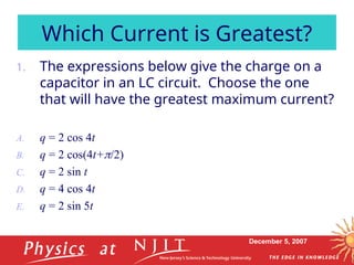
1.The expressions below give the charge on a
capacitor in an LC circuit. Choose the one
that will have the greatest maximum current?
A. q = 2 cos 4t
B. q = 2 cos(4t+/2)
C. q = 2 sin t
D. q = 4 cos 4t
E. q = 2 sin 5t
Which Current is Greatest?
6.
December 5, 2007
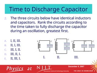
2.The three circuits below have identical inductors
and capacitors. Rank the circuits according to
the time taken to fully discharge the capacitor
during an oscillation, greatest first.
A. I, II, III.
B. II, I, III.
C. III, I, II.
D. III, II, I.
E. II, III, I.
Time to Discharge Capacitor
I. II. III.
7.
December 5, 2007
Charge,Current & Energy
Oscillations
The solution to the equation is , which gives
the charge oscillation.
From this, we can determine the corresponding oscillation of current:
And energy
But recall that , so .
That is why our graph for the energy oscillation
had the same amplitude for both UE and UB.
Note that
)
cos(
t
Q
q
0
2
2
C
q
dt
q
d
L
)
sin(
t
Q
dt
dq
i
)
(
cos
2
2
2
2
2
t
C
Q
C
q
UE
)
(
sin
2
1
2
1 2
2
2
2
t
LQ
Li
UB
LC
1
)
(
sin
2
2
2
t
C
Q
UB
C
Q
t
t
C
Q
U
U B
E
2
)]
(
sin
)
(
[cos
2
2
2
2
2
Constant
8.
December 5, 2007
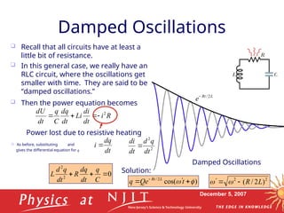
DampedOscillations
Recall that all circuits have at least a
little bit of resistance.
In this general case, we really have an
RLC circuit, where the oscillations get
smaller with time. They are said to be
“damped oscillations.”
Damped Oscillations
Then the power equation becomes
L
Rt
e 2
/
R
i
dt
di
Li
dt
dq
C
q
dt
dU 2
Power lost due to resistive heating
As before, substituting and
gives the differential equation for q dt
dq
i 2
2
dt
q
d
dt
di
0
2
2
C
q
dt
dq
R
dt
q
d
L
2
2
)
2
/
( L
R
)
cos(
2
/
t
Qe
q L
Rt
Solution:
9.
December 5, 2007
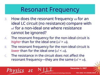
3.How does the resonant frequency for an
ideal LC circuit (no resistance) compare with
’ for a non-ideal one where resistance
cannot be ignored?
A. The resonant frequency for the non-ideal circuit is
higher than for the ideal one (’ > ).
B. The resonant frequency for the non-ideal circuit is
lower than for the ideal one (’ < ).
C. The resistance in the circuit does not affect the
resonant frequency—they are the same (’ = ).
Resonant Frequency
10.
December 5, 2007
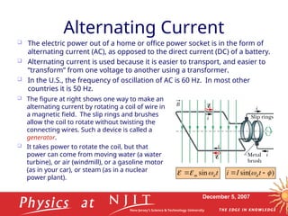
AlternatingCurrent
The electric power out of a home or office power socket is in the form of
alternating current (AC), as opposed to the direct current (DC) of a battery.
Alternating current is used because it is easier to transport, and easier to
“transform” from one voltage to another using a transformer.
In the U.S., the frequency of oscillation of AC is 60 Hz. In most other
countries it is 50 Hz.
The figure at right shows one way to make an
alternating current by rotating a coil of wire in
a magnetic field. The slip rings and brushes
allow the coil to rotate without twisting the
connecting wires. Such a device is called a
generator.
It takes power to rotate the coil, but that
power can come from moving water (a water
turbine), or air (windmill), or a gasoline motor
(as in your car), or steam (as in a nuclear
power plant).
t
d
m
sin
)
sin(
t
I
i d
11.
December 5, 2007
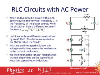
RLCCircuits with AC Power
When an RLC circuit is driven with an AC
power source, the “driving” frequency is
the frequency of the power source, while
the circuit can have a different “resonant”
frequency .
Let’s look at three different circuits driven
by an AC EMF. The device connected to
the EMF is called the “load.”
What we are interested in is how the
voltage oscillations across the load relate
to the current oscillations.
We will find that the “phase” relationships
change, depending on the type of load
(resistive, capacitive, or inductive).
d
2
)
2
/
(
/
1 L
R
LC
12.
December 5, 2007
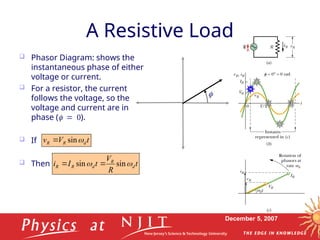
AResistive Load
Phasor Diagram: shows the
instantaneous phase of either
voltage or current.
For a resistor, the current
follows the voltage, so the
voltage and current are in
phase ().
If
Then
t
R
V
t
I
i d
R
d
R
R
sin
sin
t
V
v d
R
R
sin
13.
December 5, 2007
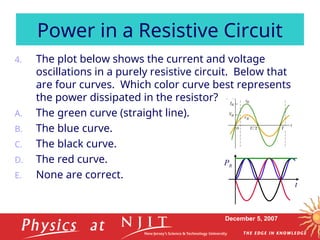
4.The plot below shows the current and voltage
oscillations in a purely resistive circuit. Below that
are four curves. Which color curve best represents
the power dissipated in the resistor?
A. The green curve (straight line).
B. The blue curve.
C. The black curve.
D. The red curve.
E. None are correct.
Power in a Resistive Circuit
PR
t
14.
December 5, 2007
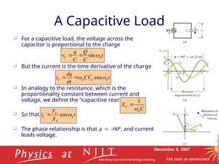
For a capacitive load, the voltage across the
capacitor is proportional to the charge
But the current is the time derivative of the charge
In analogy to the resistance, which is the
proportionality constant between current and
voltage, we define the “capacitive reactance” as
So that .
The phase relationship is that º, and current
leads voltage.
A Capacitive Load
t
X
V
i d
C
C
C
cos
C
X
d
C
1
t
C
Q
C
q
v d
C
sin
t
CV
dt
dq
i d
C
d
C
cos
15.
December 5, 2007
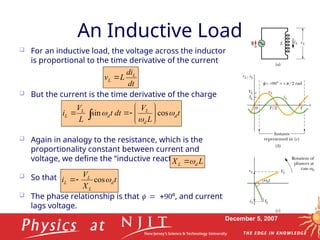
AnInductive Load
For an inductive load, the voltage across the inductor
is proportional to the time derivative of the current
But the current is the time derivative of the charge
Again in analogy to the resistance, which is the
proportionality constant between current and
voltage, we define the “inductive reactance” as
So that .
The phase relationship is that º, and current
lags voltage.
t
X
V
i d
L
L
L
cos
L
X d
L
dt
di
L
v L
L
t
L
V
dt
t
L
V
i d
d
L
d
L
L
cos
sin
16.
December 5, 2007
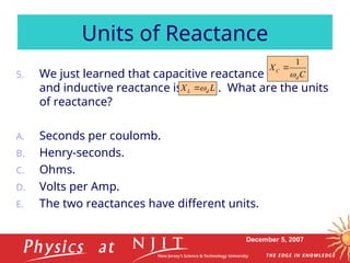
5.We just learned that capacitive reactance is
and inductive reactance is . What are the units
of reactance?
A. Seconds per coulomb.
B. Henry-seconds.
C. Ohms.
D. Volts per Amp.
E. The two reactances have different units.
Units of Reactance
L
X d
L
C
X
d
C
1
17.
December 5, 2007
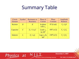
SummaryTable
Circuit
Element
Symbol Resistance or
Reactance
Phase of
Current
Phase
Constant
Amplitude
Relation
Resistor R R In phase
with vR
0º (0 rad) VR=IRR
Capacitor C XC=1/dC Leads vR
by 90º
90º (/2) VC=ICXC
Inductor L XL=dL Lags vR by
90º
90º (/2) VL=ILXL
18.
December 5, 2007
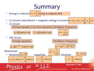
Summary
Energy in inductor:
LC circuits: total electric + magnetic energy is conserved
LC circuit:
LRC circuit:
Resistive, capacitive, inductive
2
2
1
Li
UB Energy in magnetic field
2
2
2
1
2
Li
C
q
U
U
U B
E
)
cos(
t
Q
q
LC
1
Charge equation Current equation Oscillation frequency
)
sin(
t
Q
i
Charge equation Oscillation frequency
2
2
)
2
/
( L
R
)
cos(
2
/
t
Qe
q L
Rt
t
R
V
t
I
i d
R
d
R
R
sin
sin
t
X
V
i d
C
C
C
cos
t
X
V
i d
L
L
L
cos
C
X
d
C
1
L
X d
L
R
XR
Reactances:
19.
December 5, 2007
6.How did you like using the clickers in this class?
A. Great!
B. It had its moments.
C. I could take it or leave it.
D. I would rather leave it.
E. It was the worst!
Thoughts on Clickers
20.
December 5, 2007
7.Which answer describes the most important way
that the clicker aided you in learning the material?
A. It helped me to think about the material presented
just before each question.
B. It broke up the lecture and kept me awake.
C. It tested my understanding.
D. It provided immediate feedback.
E. It showed me what others were thinking.
Thoughts on Clickers
21.
December 5, 2007
8.Which answer describes the second most important
way that the clicker aided you in learning the
material?
A. It helped me to think about the material presented
just before each question.
B. It broke up the lecture and kept me awake.
C. It tested my understanding.
D. It provided immediate feedback.
E. It showed me what others were thinking.
Thoughts on Clickers
22.
December 5, 2007
9.How would you react to clickers being used in other
classes at NJIT?
A. I think it would be excellent.
B. I think it is a good idea.
C. I wouldn’t mind.
D. I would rather not.
E. I definitely hope not.
Thoughts on Clickers
23.
December 5, 2007
10.What problems did you have with your clicker?
A. I had no problems with my clicker.
B. It was too big or bulky, a pain to carry around.
C. I had trouble remembering to bring it to class.
D. My clicker had mechanical problems.
E. I lost or misplaced it (for all or part of the semester).
Thoughts on Clickers
24.
December 5, 2007
11.If you had the choice between using a clicker versus
having a lecture quiz where you had to fill in a
scantron, which would you prefer?
A. I would prefer the clicker.
B. I would prefer the scantron quiz.
Thoughts on Clickers
25.
December 5, 2007
12.Please click any button on your clicker as you turn
your clicker in. This will register your name as
having turned in your clicker.
Have a Nice Day

![December 5, 2007
Charge, Current & Energy
Oscillations
The solution to the equation is , which gives
the charge oscillation.
From this, we can determine the corresponding oscillation of current:
And energy
But recall that , so .
That is why our graph for the energy oscillation
had the same amplitude for both UE and UB.
Note that
)
cos(
t
Q
q
0
2
2
C
q
dt
q
d
L
)
sin(
t
Q
dt
dq
i
)
(
cos
2
2
2
2
2
t
C
Q
C
q
UE
)
(
sin
2
1
2
1 2
2
2
2
t
LQ
Li
UB
LC
1
)
(
sin
2
2
2
t
C
Q
UB
C
Q
t
t
C
Q
U
U B
E
2
)]
(
sin
)
(
[cos
2
2
2
2
2
Constant](https://image.slidesharecdn.com/physics121lecture13-250416233850-c4bc0b72/85/physics121_lecture13-oscillatoins-and-modern-physics-7-320.jpg)