Downloaded 150 times


![Capacitor Rules and Equations
• For capacitors, we have the
following rules and equations
which hold:
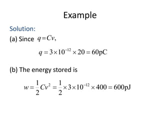
q Cv,
w(t )
1
2
Cv (t )
2
dv
i C
dt
1 t
v
idt v(0)
0
C
CX = #[F]
+ vC
iC](https://image.slidesharecdn.com/newmicrosoftofficepowerpointpresentation-131210104509-phpapp01/85/Circuits-22-320.jpg)


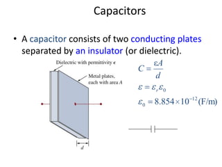
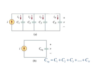
Capacitors and inductors are passive circuit elements that can store energy. - Capacitors store energy in an electric field between conducting plates separated by an insulator. The capacitance is affected by the area of the plates, distance between plates, and the material between the plates. - Inductors store energy in a magnetic field created by current through a coil of wire. The inductance depends on the number of wire turns, length of the coil, and material inside the coil. - Capacitors and inductors have characteristic equations relating voltage, current, charge, and energy that make them useful for circuit analysis. Their properties allow them to be combined in series and parallel configurations.