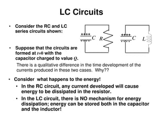
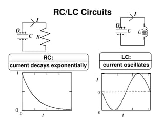
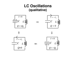
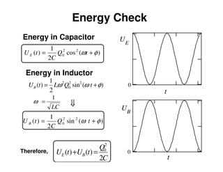
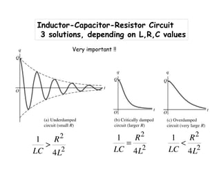
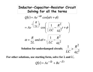
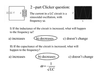
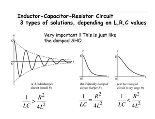
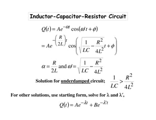
1) The document discusses LC circuits, noting a qualitative difference in how currents develop in RC versus LC circuits. In an LC circuit, energy can be stored in both the inductor and capacitor without dissipation, unlike an RC circuit where energy is dissipated in the resistor.
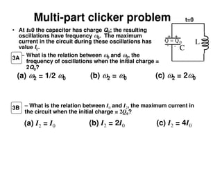
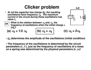
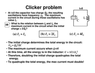
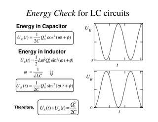
2) An LC circuit with an initially charged capacitor will undergo oscillations of the current, not exponential decay as in an RC circuit. The frequency of these oscillations is determined to be 1/sqrt(LC) from the equations for the energy stored in each component.
3) Increasing the inductance decreases the oscillation frequency in an LC circuit, while increasing the capacitance also decreases the frequency, according to the governing equation relating the
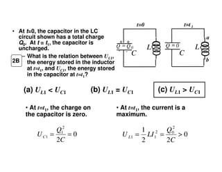
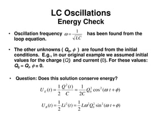
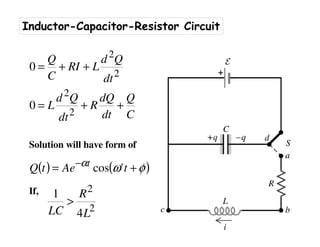
![Inductor-Capacitor Circuits
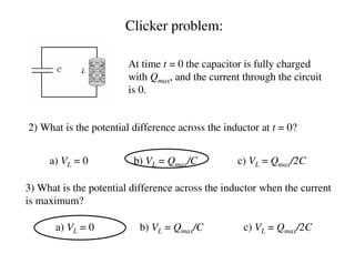
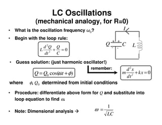
Solving a LC circuit problem; Suppose ωωωω=1/sqrt(LC)=3 and
given the initial conditions,
Solve find Q0 and φφφφ0000,,,, to get complete solution using,
and we find,
( )
( ) AtI
CtQ
150
50
==
==
( ) ( )
( ) ( ) ( )0000
00
0sin30sin150
0cos50
φφω
φ
+−=+−===
+===
QQtI
QtQ
( ) ( ) ( )[ ]
o
45,
35
15
tan.
25,cossin
3
15
5
00
0
2
00
2
0
22
0
2
2
−=
⋅
−=
==+=
−+
φφ
φφ
inv
QQQ](https://image.slidesharecdn.com/p272fall10-19pdf-191130122427/85/AC-Circuit-Theory-18-320.jpg)
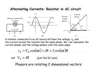
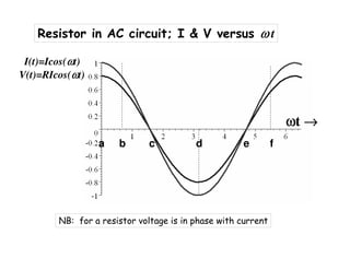
![Inductor-Capacitor (LC) Circuit Example
Solving a LC circuit problem; Suppose ωωωω=1/sqrt(LC)=3 and
given the initial conditions,
Solve find Q0 and φφφφ0000,,,, to get complete solution using,
and we find,
( )
( ) AtI
CtQ
150
50
==
==
( ) ( )
( ) ( ) ( )0000
00
0sin30sin150
0cos50
φφω
φ
+−=+−===
+===
QQtI
QtQ
( ) ( ) ( )[ ]
o
45,
35
15
tan.
25,cossin
3
15
5
00
0
2
00
2
0
22
0
2
2
−=
⋅
−=
==+=
−+
φφ
φφ
inv
QQQ](https://image.slidesharecdn.com/p272fall10-19pdf-191130122427/85/AC-Circuit-Theory-27-320.jpg)
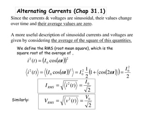
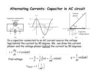
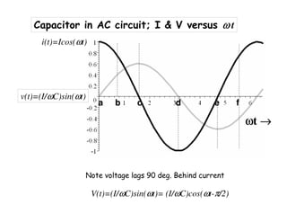
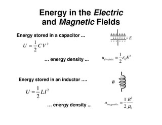
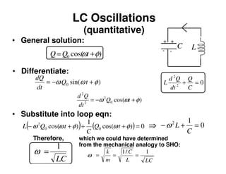
![Alternating Currents ; Capacitor in AC circuit
We stated that voltage lags by 90 deg., so equivalent solution is
( ) [ ]
t
C
I
tt
C
I
t
C
I
v
ω
ω
ωω
ω
ω
ω
sin
90sinsin90coscos90cos
=
+=−=
1
C
XC
ω
=We define the capacitive reactance, XC, as
C
MAX
cap XI
C
I
C
I
V =
==
ωω
1
Like: VR = IR
But frequency dependent](https://image.slidesharecdn.com/p272fall10-19pdf-191130122427/85/AC-Circuit-Theory-38-320.jpg)