Downloaded 51 times
![RESISTOR (R)
A resistor is an electrical
component that implements
electrical resistance as a
circuit element. In electronic
circuits, resistors are used to
reduce current flow, adjust
signal levels, to divide
voltages, bias active
elements, and terminate
transmission lines, among
other uses.[1]
Fig.2 Electronic Symbol
(Source: wikipedia)
Fig.1 A typical axial-lead
resistor (Source:
wikipedia)
2](https://image.slidesharecdn.com/odemodelingsaqib12075768-170424195648/75/Modeling-of-an-RLC-circuit-3-2048.jpg)
![INDUCTOR (L)
An inductor, also called a coil
or reactor, is an electrical
component that stores
electrical energy in a
magnetic field when electric
current is flowing through it.
An inductor typically consists
of an electric conductor, such
as a wire, that is wound into a
coil.[2]
Fig.3 A selection of low-
value inductors
(Source: wikipedia)
Fig.4 Electronic Symbol
(Source: wikipedia)
3](https://image.slidesharecdn.com/odemodelingsaqib12075768-170424195648/75/Modeling-of-an-RLC-circuit-4-2048.jpg)
![CAPACITOR (C)
A capacitor is an electrical
component that stores
electrical energy in an
electric field. The effect of a
capacitor is known as
capacitance. Capacitors are
widely used in electronic
circuits for blocking direct
current while allowing
alternating current to pass. In
analog filter networks, they
smooth the output of power
supplies.[3]
Fig.5 Different types of
capacitors
(Source: wikipedia)
Fig.6 Electronic
Symbol(Source:
wikipedia) 4](https://image.slidesharecdn.com/odemodelingsaqib12075768-170424195648/75/Modeling-of-an-RLC-circuit-5-2048.jpg)
![RLC CIRCUIT
An RLC circuit is an electrical circuit consisting of a
resistor (R), an inductor (L), and a capacitor (C),
connected in series or in parallel. The name of the
circuit is derived from the letters that are used to
denote the constituent components of this circuit,
where the sequence of the components may vary from
RLC. [4]
Fig.5 A series RLC circuit: a resistor, inductor, and a
capacitor (Source: wikipedia)
5](https://image.slidesharecdn.com/odemodelingsaqib12075768-170424195648/75/Modeling-of-an-RLC-circuit-6-2048.jpg)


![for i=1:n+1
q=(964/58981)*sin(30*x(i)) -
(120/58981)*cos(30*x(i)) + exp(-
50*x(i))*((-2292/(58981*15))*
sin(150*x(i)) + (120/58981)*
cos(150*x(i)));
end
q'
a=[x' y' yp'];
13
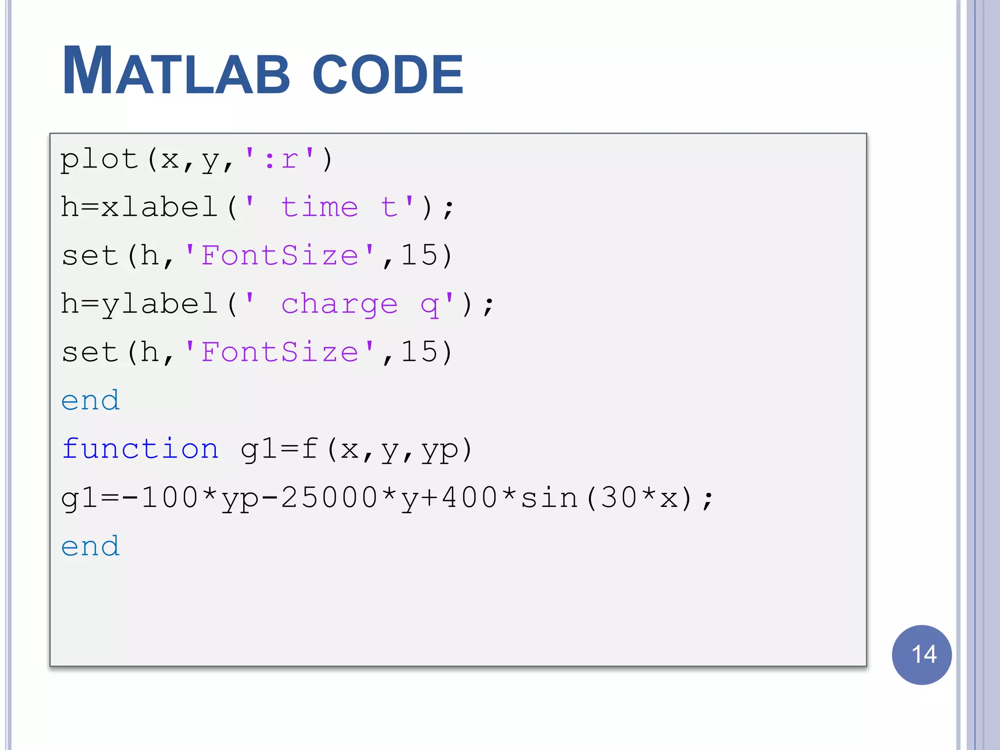
MATLAB CODE](https://image.slidesharecdn.com/odemodelingsaqib12075768-170424195648/75/Modeling-of-an-RLC-circuit-14-2048.jpg)

![REFERENCES
[1] https://en.wikipedia.org/wiki/Resistor
[2] https://en.wikipedia.org/wiki/Inductor
[3] https://en.wikipedia.org/wiki/Capacitor
[4] https://en.wikipedia.org/wiki/RLC_circuit
16](https://image.slidesharecdn.com/odemodelingsaqib12075768-170424195648/75/Modeling-of-an-RLC-circuit-17-2048.jpg)


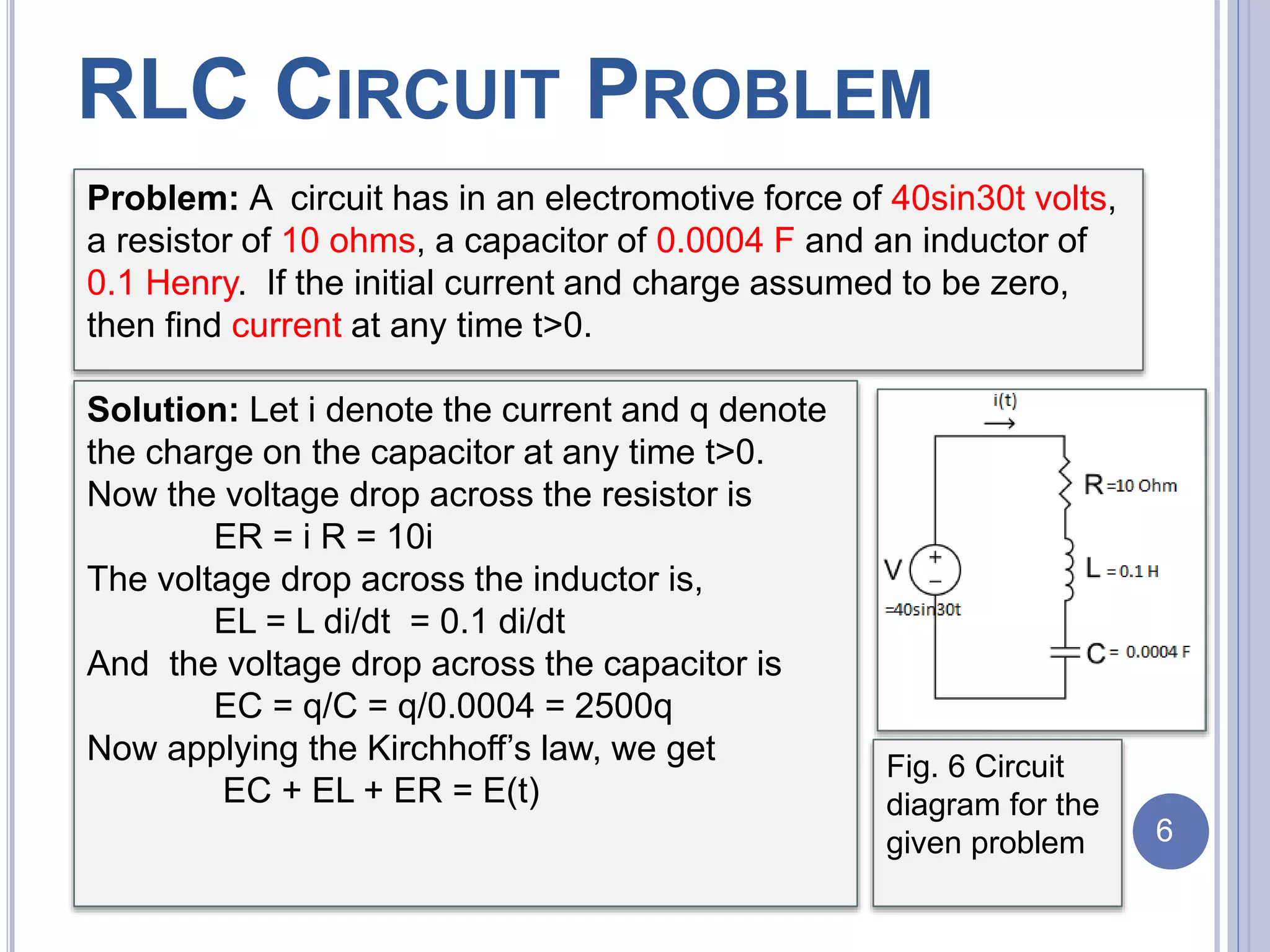
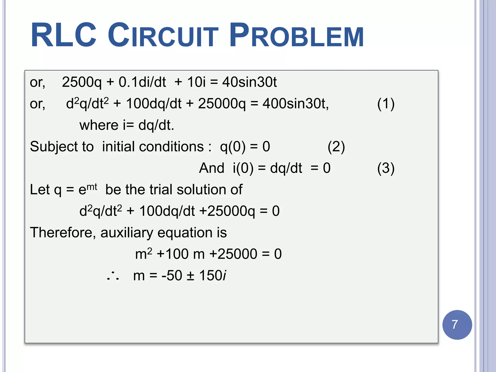
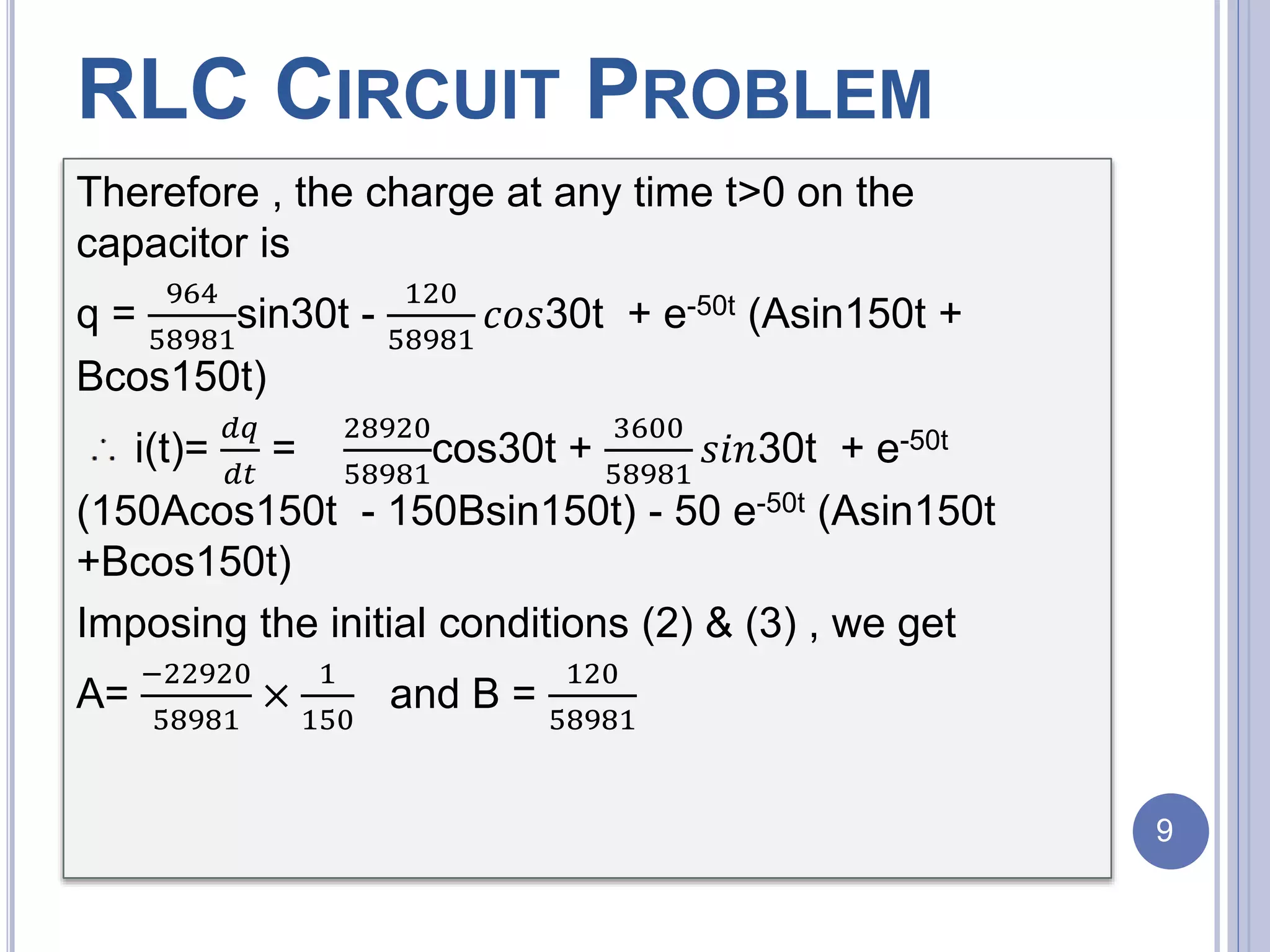
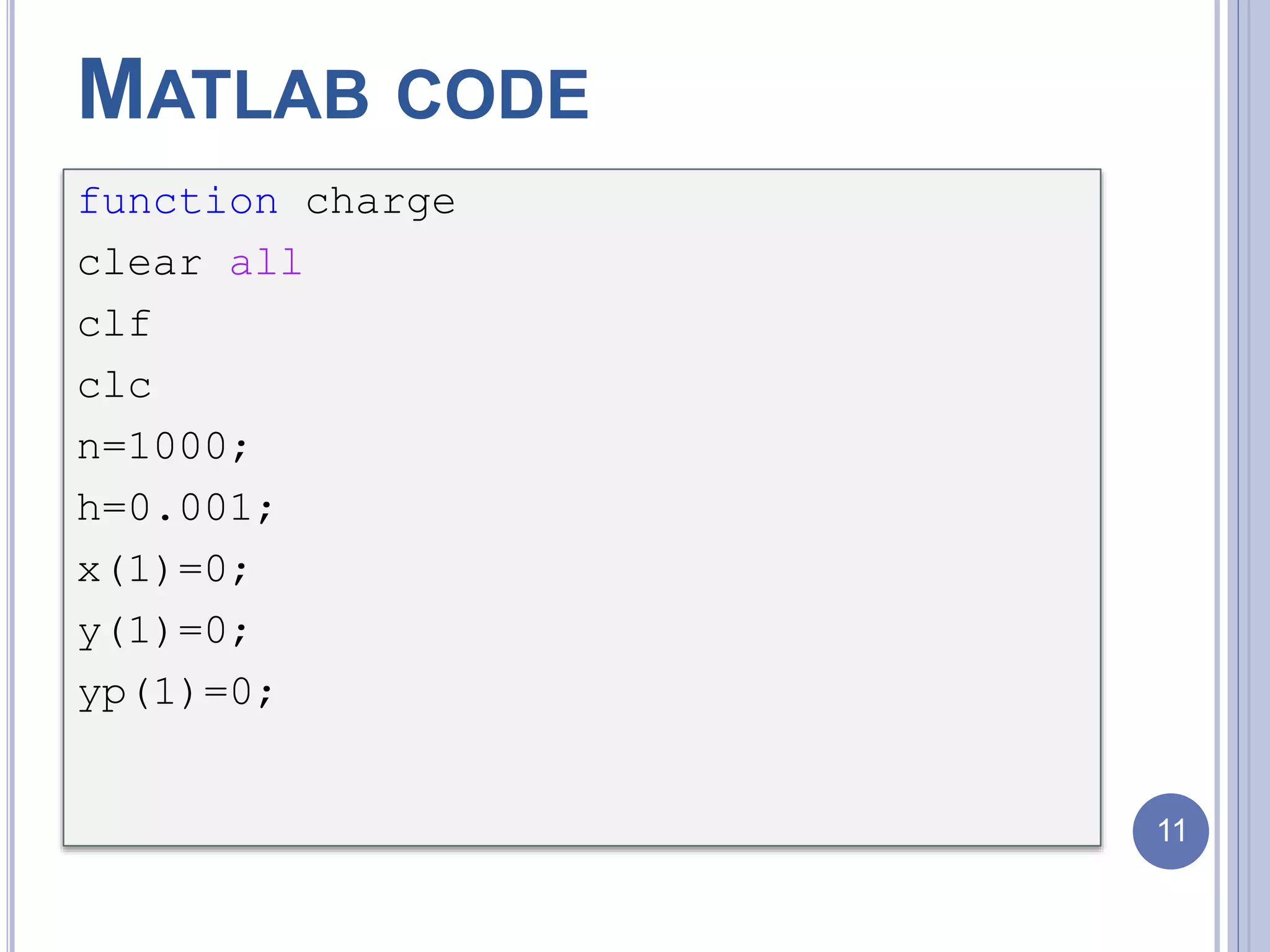
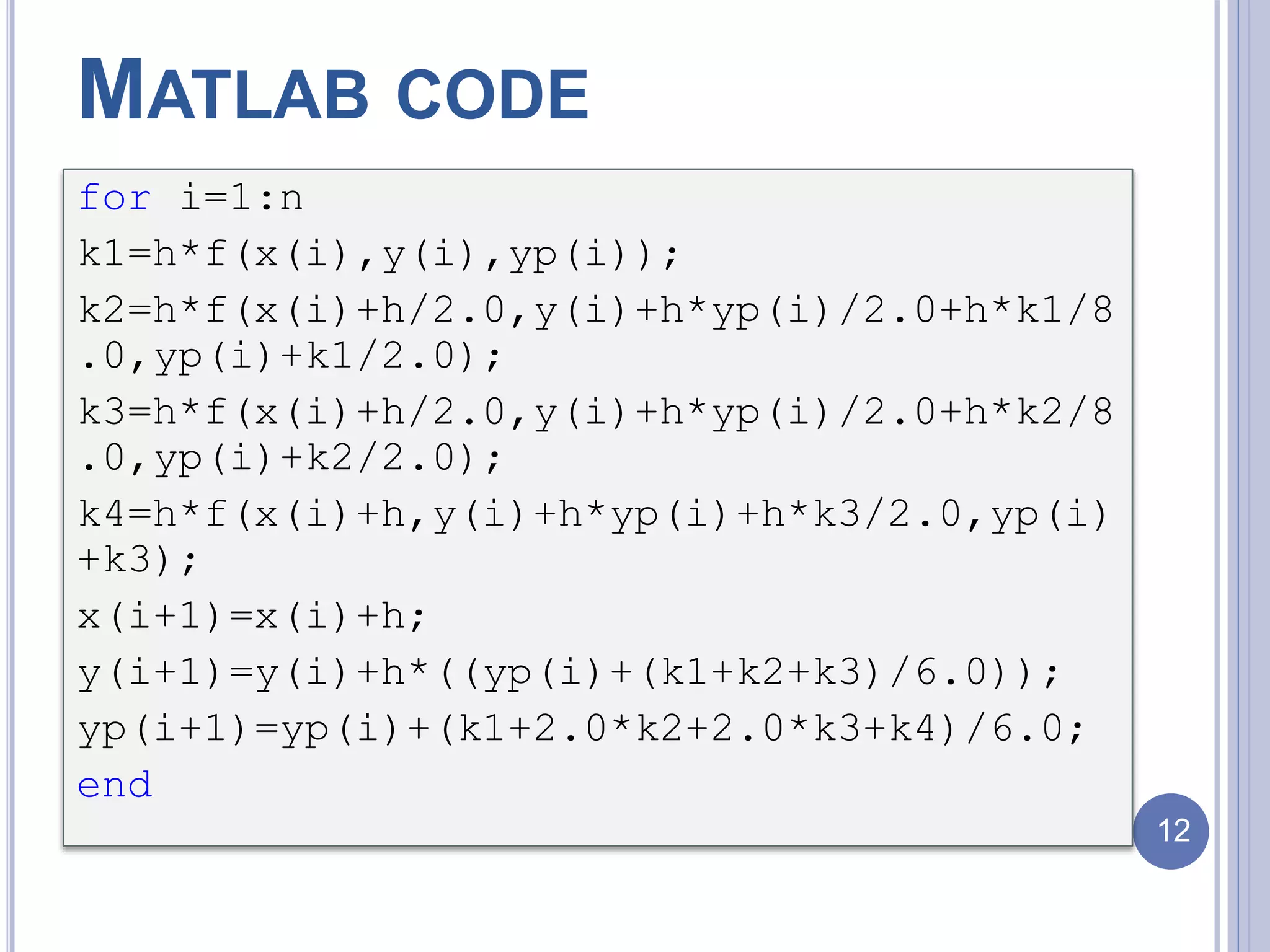
The document discusses an RLC circuit problem involving a resistor, inductor, and capacitor, detailing their definitions and functions within an electronic circuit. It presents a specific circuit problem with given parameters and derives the charge and current at any time t>0 using differential equations and MATLAB code. The document includes references and figures to support the content.