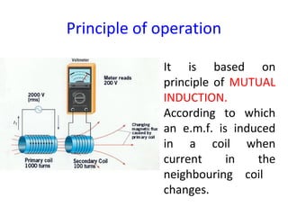
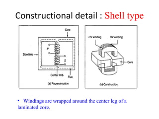
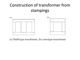
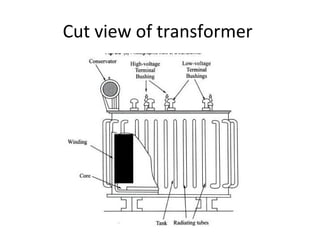
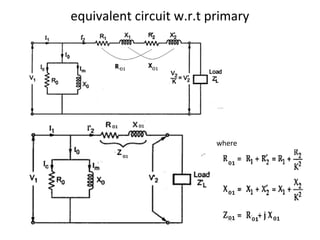
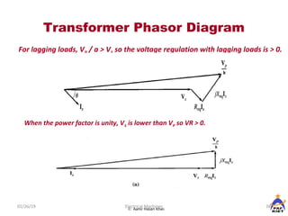
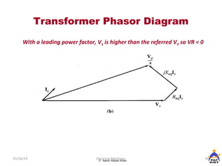
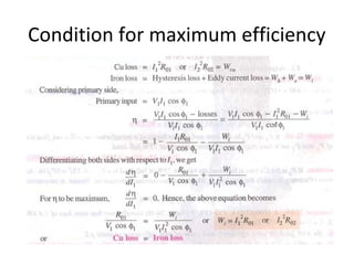
SlideShare a Scribd company logo
Transformers
Transformer
An A.C. device used to change high voltage low
current A.C. into low voltage high current A.C. and
vice-versa without changing the frequency
In brief,
1. Transfers electric power from one circuit to another
2. It does so without a change of frequency
3. It accomplishes this by electromagnetic induction
4. Where the two electric circuits are in mutual
inductive influence of each other.
Principle of operation
It is based on
principle of MUTUAL
INDUCTION.
According to which
an e.m.f. is induced
in a coil when
current in the
neighbouring coil
changes.
Constructional detail : Shell type
• Windings are wrapped around the center leg of a
laminated core.
Core type
• Windings are wrapped around two sides of a laminated square
core.
Sectional view of transformers
Note:
High voltage conductors are smaller cross section conductors
than the low voltage coils
Construction of transformer from
stampings
Core type
Fig1: Coil and laminations of
core type transformer
Fig2: Various types of cores
Shell type
• The HV and LV
windings are split
into no. of sections
• Where HV winding
lies between two LV
windings
• In sandwich coils
leakage can be
controlledFig: Sandwich windings
Cut view of transformer
Transformer with conservator and
breather
Working of a transformer
1. When current in the primary coil
changes being alternating in
nature, a changing magnetic field
is produced
2. This changing magnetic field gets
associated with the secondary
through the soft iron core
3. Hence magnetic flux linked with
the secondary coil changes.
4. Which induces e.m.f. in the
secondary.
Ideal Transformers
• Zero leakage flux:
-Fluxes produced by the primary and secondary currents
are confined within the core
• The windings have no resistance:
- Induced voltages equal applied voltages
• The core has infinite permeability
- Reluctance of the core is zero
- Negligible current is required to establish magnetic
flux
• Loss-less magnetic core
- No hysteresis or eddy currents
Ideal transformer
V1 – supply voltage ; I1- noload input current ;
V2- output voltgae; I2- output current
Im- magnetising current;
E1-self induced emf ; E2- mutually induced emf
EMF equation of a transformer
• Worked out on board /
• Refer pdf file: emf-equation-of-tranformer
Phasor diagram: Transformer on No-
load
Transformer on load assuming no
voltage drop in the winding
Fig shows the Phasor diagram of a
transformer on load by assuming
1.No voltage drop in the winding
2.Equal no. of primary and secondary turns
Transformer on load
Fig. a: Ideal transformer on load
Fig. b: Main flux and leakage
flux in a transformer
Phasor diagram of transformer with
UPF load
Phasor diagram of transformer with
lagging p.f load
Phasor diagram of transformer with
leading p.f load
Equivalent circuit of a transformer
No load equivalent circuit:
Equivalent circuit parameters referred to
primary and secondary sides respectively
Contd.,
• The effect of circuit parameters shouldn’t be changed while
transferring the parameters from one side to another side
• It can be proved that a resistance of R2 in sec. is equivalent
to R2/k2
will be denoted as R2’(ie. Equivalent sec. resistance
w.r.t primary) which would have caused the same loss as R2
in secondary,
2
2
2
2
1
2'
2
2
2
2
'
2
2
1
k
R
R
=






=
=
R
I
I
RIRI
Transferring secondary parameters to
primary side
Equivalent circuit referred to
secondary side
•Transferring primary side parameters to secondary side
Similarly exciting circuit parameters are also transferred to
secondary as Ro’ and Xo’
equivalent circuit w.r.t primary
where
Approximate equivalent circuit
• Since the noload current is 1% of the full load
current, the nolad circuit can be neglected
Transformer Tests
Electrical Machines
•The performance of a transformer can be calculated on the basis of
equivalent circuit
•The four main parameters of equivalent circuit are:
- R01 as referred to primary (or secondary R02)
- the equivalent leakage reactance X01 as referred to primary
(or secondary X02)
- Magnetising susceptance B0 ( or reactance X0)
- core loss conductance G0 (or resistance R0)
•The above constants can be easily determined by two tests
- Oper circuit test (O.C test / No load test)
- Short circuit test (S.C test/Impedance test)
•These tests are economical and convenient
- these tests furnish the result without actually loading the
transformer
In Open Circuit Test the transformer’s secondary winding is open-circuited, and
its primary winding is connected to a full-rated line voltage.
• Usually conducted on
H.V side
• To find
(i) No load loss or core
loss
(ii) No load current Io
which is helpful in
finding Go(or Ro ) and Bo
(or Xo )
2
0
2
00
2
0
oc
00
2
0oc
0
0
o000
22
000m
00wc
00
0
000
BesusceptancExciting&
V
W
GeconductancExciting;GVW
Y;YVI
sinII
cosII
cos
coslossCore
GY
V
I
-IIIor
Ior
IV
W
IVW
w
oc
oc
−=
=∴=
=∴=
==
=
=
==
φ
φ
φ
φ
µ
Open-circuit Test
0
0
0
0
0
0
0
0
V
I
B
V
I
G
I
V
X
I
V
R
w
w
µ
µ
=
=
=
=
Short-circuit Test
In Short Circuit Test the secondary terminals are short circuited, and the
primary terminals are connected to a fairly low-voltage source
The input voltage is adjusted until the current in the short circuited
windings is equal to its rated value. The input voltage, current and power is
measured.
• Usually conducted on L.V side
• To find
(i) Full load copper loss – to pre determine the
efficiency
(ii) Z01 or Z02; X01 or X02; R01 or R02 - to predetermine the
voltage regulation
Contd…
2
01
2
0101
01
2
sc
01
01
2
sc
X
W
R
WlossculoadFull
RZ
I
V
Z
I
RI
sc
sc
sc
sc
−=∴
=
=
==
Transformer Voltage Regulation
and Efficiency
Electrical Machines
The output voltage of a transformer varies with the load even if the input
voltage remains constant. This is because a real transformer has series
impedance within it. Full load Voltage Regulation is a quantity that compares
the output voltage at no load with the output voltage at full load, defined by
this equation:
%100downRegulation
%100upRegulation
,
,,
,
,,
×
−
=
×
−
=
nlS
flSnlS
flS
flSnlS
V
VV
V
VV ( )
( )
%100
/
downRegulation
%100
/
upRegulation
V
V
knoloadAt
,
,
,
,
p
s
x
V
VkV
x
V
VkV
nlS
flSP
flS
flSP
−
=
−
=
=
Ideal transformer, VR = 0%.
voltageload-no
voltageload-fullvoltageload-no
regulationVoltage
−
=






=
1
2
12
N
N
VV
p
s
p
s
N
N
V
V
=recall
Secondary voltage on no-load
V2 is a secondary terminal voltage on full load






−





=
1
2
1
2
1
2
1
regulationVoltage
N
N
V
V
N
N
V
Substitute we have
Transformer Phasor Diagram
01/26/19 36Electrical Machines© Aamir Hasan Khan
To determine the voltage regulation of a transformer, it is necessary
understand the voltage drops within it.
Transformer Phasor Diagram
01/26/19 37Electrical Machines© Aamir Hasan Khan
Ignoring the excitation of the branch (since the current flow through the
branch is considered to be small), more consideration is given to the series
impedances (Req +jXeq).
Voltage Regulation depends on magnitude of the series impedance and the
phase angle of the current flowing through the transformer.
Phasor diagrams will determine the effects of these factors on the voltage
regulation. A phasor diagram consist of current and voltage vectors.
Assume that the reference phasor is the secondary voltage, VS. Therefore
the reference phasor will have 0 degrees in terms of angle.
Based upon the equivalent circuit, apply Kirchoff Voltage Law,
SeqSeqS
P
IjXIRV
k
V
++=
Transformer Phasor Diagram
01/26/19 38Electrical Machines© Aamir Hasan Khan
For lagging loads, VP / a > VS so the voltage regulation with lagging loads is > 0.
When the power factor is unity, VS is lower than VP so VR > 0.
Transformer Phasor Diagram
01/26/19 39Electrical Machines© Aamir Hasan Khan
With a leading power factor, VS is higher than the referred VP so VR < 0
Transformer Phasor Diagram
Electrical Machines
For lagging loads, the vertical components of Req
and Xeq
will partially
cancel each other. Due to that, the angle of VP
/a will be very small, hence
we can assume that VP
/k is horizontal. Therefore the approximation will
be as follows:
Formula: voltage regulation
leadingfor'-'andlaggingfor''
V
sincos
V
V
regulation%
luesprimary vaofIn terms
leadingfor'-'andlaggingfor''
V
sincos
V
V
regulation%
valuessecondaryofIn terms
1
10111011
1
'
21
20
20222022
20
220
+
±
=
−
=
+
±
=
−
=
where
XIRIV
where
XIRIV
φφ
φφ
Transformer Efficiency
Electrical Machines
Transformer efficiency is defined as (applies to motors, generators and
transformers):
%100×=
in
out
P
P
η
%100×
+
=
lossout
out
PP
P
η
Types of losses incurred in a transformer:
Copper I2
R losses
Hysteresis losses
Eddy current losses
Therefore, for a transformer, efficiency may be calculated using the following:
%100
cos
cos
x
IVPP
IV
SScoreCu
SS
θ
θ
η
++
=
Losses in a transformer
Core or Iron loss:
Copper loss:
Condition for maximum efficiency
Contd.,
The load at which the two losses are equal =
All day efficiency
hours)24(
kWhinInput
kWhinoutput
in wattsinput
in wattsputout
efficiencycommercialordinary
day forall =
=
η
•All day efficiency is always less than the commercial efficiency

More Related Content

What's hot

What's hot (20)

Half wave control rectifier with RL load
Half wave control rectifier with RL loadHalf wave control rectifier with RL load
Half wave control rectifier with RL load
 
Losses dc machines
Losses dc machinesLosses dc machines
Losses dc machines
 
Torque - Slip Characteristic of a three phase induction motor
Torque - Slip Characteristic of a three   phase induction motorTorque - Slip Characteristic of a three   phase induction motor
Torque - Slip Characteristic of a three phase induction motor
 
open circuit and short circuit test on transformer
open circuit and short circuit test on transformeropen circuit and short circuit test on transformer
open circuit and short circuit test on transformer
 
PROTECTION CIRCUIT OF SCR
PROTECTION CIRCUIT OF SCRPROTECTION CIRCUIT OF SCR
PROTECTION CIRCUIT OF SCR
 
UJT (industrial electronic)
UJT (industrial electronic)UJT (industrial electronic)
UJT (industrial electronic)
 
DC motors characteristics, Torque & Speed Equations, Torque -Armature current...
DC motors characteristics, Torque & Speed Equations, Torque -Armature current...DC motors characteristics, Torque & Speed Equations, Torque -Armature current...
DC motors characteristics, Torque & Speed Equations, Torque -Armature current...
 
Armature windings
Armature windingsArmature windings
Armature windings
 
Transformer ppt
Transformer pptTransformer ppt
Transformer ppt
 
IDEAL AND PRACTICAL TRANSFORMER, EQUIVALENT CIRCUIT OF TRANSFORMER|DAY5|BASIC...
IDEAL AND PRACTICAL TRANSFORMER, EQUIVALENT CIRCUIT OF TRANSFORMER|DAY5|BASIC...IDEAL AND PRACTICAL TRANSFORMER, EQUIVALENT CIRCUIT OF TRANSFORMER|DAY5|BASIC...
IDEAL AND PRACTICAL TRANSFORMER, EQUIVALENT CIRCUIT OF TRANSFORMER|DAY5|BASIC...
 
Classification of transmission lines
Classification of transmission linesClassification of transmission lines
Classification of transmission lines
 
Power Electronics - Thyristor Commutation
Power Electronics - Thyristor CommutationPower Electronics - Thyristor Commutation
Power Electronics - Thyristor Commutation
 
3 phase Induction Motor Torque-slip characteristics and Related problems
3 phase Induction Motor Torque-slip characteristics and Related problems3 phase Induction Motor Torque-slip characteristics and Related problems
3 phase Induction Motor Torque-slip characteristics and Related problems
 
dc Generator Ppt
dc Generator Pptdc Generator Ppt
dc Generator Ppt
 
Single phase transformer
Single phase transformerSingle phase transformer
Single phase transformer
 
Electrical machines 2 AC Machines
Electrical machines 2 AC MachinesElectrical machines 2 AC Machines
Electrical machines 2 AC Machines
 
3 ph induction motor ppt
3 ph induction motor ppt3 ph induction motor ppt
3 ph induction motor ppt
 
Chapter 3 transmission line performance
Chapter 3  transmission line performanceChapter 3  transmission line performance
Chapter 3 transmission line performance
 
Armature Reaction
Armature ReactionArmature Reaction
Armature Reaction
 
Transformer : Equivalent Circuit
Transformer : Equivalent CircuitTransformer : Equivalent Circuit
Transformer : Equivalent Circuit
 

Similar to Transformer

ECE 505 Power electronics final paper
ECE 505 Power electronics final paperECE 505 Power electronics final paper
ECE 505 Power electronics final paper
Rob Garrone
 

Similar to Transformer (20)

Transformer_theory.pptx
Transformer_theory.pptxTransformer_theory.pptx
Transformer_theory.pptx
 
transformers.ppt
transformers.ppttransformers.ppt
transformers.ppt
 
Akshay kumar
Akshay kumarAkshay kumar
Akshay kumar
 
Open circuit and Short circuit test on transformer
Open circuit and Short circuit test on transformerOpen circuit and Short circuit test on transformer
Open circuit and Short circuit test on transformer
 
Transformers 31.03.2020.pptx
Transformers 31.03.2020.pptxTransformers 31.03.2020.pptx
Transformers 31.03.2020.pptx
 
Chapter 7 transformers
Chapter 7 transformersChapter 7 transformers
Chapter 7 transformers
 
Transformers 25.02.2020.pptx
Transformers 25.02.2020.pptxTransformers 25.02.2020.pptx
Transformers 25.02.2020.pptx
 
Transformer Course Lab.pdf
Transformer Course Lab.pdfTransformer Course Lab.pdf
Transformer Course Lab.pdf
 
Transformers basic electrical engineering
Transformers basic electrical engineeringTransformers basic electrical engineering
Transformers basic electrical engineering
 
PED drivers t5656979089897877ghvvnvgcxxn
PED drivers t5656979089897877ghvvnvgcxxnPED drivers t5656979089897877ghvvnvgcxxn
PED drivers t5656979089897877ghvvnvgcxxn
 
Power transformer
Power transformerPower transformer
Power transformer
 
O.C & S.C Test, Sumpner or back to back Test, Condition for maximum efficienc...
O.C & S.C Test, Sumpner or back to back Test, Condition for maximum efficienc...O.C & S.C Test, Sumpner or back to back Test, Condition for maximum efficienc...
O.C & S.C Test, Sumpner or back to back Test, Condition for maximum efficienc...
 
ECE 505 Power electronics final paper
ECE 505 Power electronics final paperECE 505 Power electronics final paper
ECE 505 Power electronics final paper
 
Rectifiers (ac dc)
Rectifiers (ac dc) Rectifiers (ac dc)
Rectifiers (ac dc)
 
Transformer
TransformerTransformer
Transformer
 
Transformers_SNH.pptx
Transformers_SNH.pptxTransformers_SNH.pptx
Transformers_SNH.pptx
 
Inverter
InverterInverter
Inverter
 
Transformer
TransformerTransformer
Transformer
 
Chap 2 basic electronics gp 1
Chap 2 basic electronics gp 1Chap 2 basic electronics gp 1
Chap 2 basic electronics gp 1
 
Voltage regulator
Voltage regulatorVoltage regulator
Voltage regulator
 

More from JaydevVadachhak

More from JaydevVadachhak (20)

Complain management system
Complain management systemComplain management system
Complain management system
 
Formal and informal letters
Formal and informal lettersFormal and informal letters
Formal and informal letters
 
Communicating across cultures
Communicating across culturesCommunicating across cultures
Communicating across cultures
 
7 cs of communication
7 cs of communication7 cs of communication
7 cs of communication
 
communication types , levels , barriers
 communication types , levels , barriers communication types , levels , barriers
communication types , levels , barriers
 
social responsibility
 social responsibility social responsibility
social responsibility
 
2. personality development
2. personality development2. personality development
2. personality development
 
professional ethics and human values
 professional ethics and human values professional ethics and human values
professional ethics and human values
 
Succesive differntiation
Succesive differntiationSuccesive differntiation
Succesive differntiation
 
Electromagnetism
ElectromagnetismElectromagnetism
Electromagnetism
 
Electrical safety
Electrical safetyElectrical safety
Electrical safety
 
Non verbal communication
Non verbal communicationNon verbal communication
Non verbal communication
 
Internal communication
Internal communicationInternal communication
Internal communication
 
Ir spectroscopy
Ir spectroscopyIr spectroscopy
Ir spectroscopy
 
Nanomaterials
NanomaterialsNanomaterials
Nanomaterials
 
cement
 cement cement
cement
 
Cathodic protection
Cathodic protectionCathodic protection
Cathodic protection
 
1 bch101 water treatment
1 bch101  water treatment1 bch101  water treatment
1 bch101 water treatment
 
Handprint activities and sustainability
Handprint activities and sustainabilityHandprint activities and sustainability
Handprint activities and sustainability
 
Solid waste
Solid wasteSolid waste
Solid waste
 

Recently uploaded

Laundry management system project report.pdf
Laundry management system project report.pdfLaundry management system project report.pdf
Laundry management system project report.pdf
Kamal Acharya
 
Digital Signal Processing Lecture notes n.pdf
Digital Signal Processing Lecture notes n.pdfDigital Signal Processing Lecture notes n.pdf
Digital Signal Processing Lecture notes n.pdf
AbrahamGadissa
 
Automobile Management System Project Report.pdf
Automobile Management System Project Report.pdfAutomobile Management System Project Report.pdf
Automobile Management System Project Report.pdf
Kamal Acharya
 
ONLINE VEHICLE RENTAL SYSTEM PROJECT REPORT.pdf
ONLINE VEHICLE RENTAL SYSTEM PROJECT REPORT.pdfONLINE VEHICLE RENTAL SYSTEM PROJECT REPORT.pdf
ONLINE VEHICLE RENTAL SYSTEM PROJECT REPORT.pdf
Kamal Acharya
 

Recently uploaded (20)

ENERGY STORAGE DEVICES INTRODUCTION UNIT-I
ENERGY STORAGE DEVICES  INTRODUCTION UNIT-IENERGY STORAGE DEVICES  INTRODUCTION UNIT-I
ENERGY STORAGE DEVICES INTRODUCTION UNIT-I
 
Laundry management system project report.pdf
Laundry management system project report.pdfLaundry management system project report.pdf
Laundry management system project report.pdf
 
KIT-601 Lecture Notes-UNIT-4.pdf Frequent Itemsets and Clustering
KIT-601 Lecture Notes-UNIT-4.pdf Frequent Itemsets and ClusteringKIT-601 Lecture Notes-UNIT-4.pdf Frequent Itemsets and Clustering
KIT-601 Lecture Notes-UNIT-4.pdf Frequent Itemsets and Clustering
 
A CASE STUDY ON ONLINE TICKET BOOKING SYSTEM PROJECT.pdf
A CASE STUDY ON ONLINE TICKET BOOKING SYSTEM PROJECT.pdfA CASE STUDY ON ONLINE TICKET BOOKING SYSTEM PROJECT.pdf
A CASE STUDY ON ONLINE TICKET BOOKING SYSTEM PROJECT.pdf
 
Cloud-Computing_CSE311_Computer-Networking CSE GUB BD - Shahidul.pptx
Cloud-Computing_CSE311_Computer-Networking CSE GUB BD - Shahidul.pptxCloud-Computing_CSE311_Computer-Networking CSE GUB BD - Shahidul.pptx
Cloud-Computing_CSE311_Computer-Networking CSE GUB BD - Shahidul.pptx
 
KIT-601 Lecture Notes-UNIT-5.pdf Frame Works and Visualization
KIT-601 Lecture Notes-UNIT-5.pdf Frame Works and VisualizationKIT-601 Lecture Notes-UNIT-5.pdf Frame Works and Visualization
KIT-601 Lecture Notes-UNIT-5.pdf Frame Works and Visualization
 
Explosives Industry manufacturing process.pdf
Explosives Industry manufacturing process.pdfExplosives Industry manufacturing process.pdf
Explosives Industry manufacturing process.pdf
 
RESORT MANAGEMENT AND RESERVATION SYSTEM PROJECT REPORT.pdf
RESORT MANAGEMENT AND RESERVATION SYSTEM PROJECT REPORT.pdfRESORT MANAGEMENT AND RESERVATION SYSTEM PROJECT REPORT.pdf
RESORT MANAGEMENT AND RESERVATION SYSTEM PROJECT REPORT.pdf
 
retail automation billing system ppt.pptx
retail automation billing system ppt.pptxretail automation billing system ppt.pptx
retail automation billing system ppt.pptx
 
The Benefits and Techniques of Trenchless Pipe Repair.pdf
The Benefits and Techniques of Trenchless Pipe Repair.pdfThe Benefits and Techniques of Trenchless Pipe Repair.pdf
The Benefits and Techniques of Trenchless Pipe Repair.pdf
 
Construction method of steel structure space frame .pptx
Construction method of steel structure space frame .pptxConstruction method of steel structure space frame .pptx
Construction method of steel structure space frame .pptx
 
Digital Signal Processing Lecture notes n.pdf
Digital Signal Processing Lecture notes n.pdfDigital Signal Processing Lecture notes n.pdf
Digital Signal Processing Lecture notes n.pdf
 
shape functions of 1D and 2 D rectangular elements.pptx
shape functions of 1D and 2 D rectangular elements.pptxshape functions of 1D and 2 D rectangular elements.pptx
shape functions of 1D and 2 D rectangular elements.pptx
 
Automobile Management System Project Report.pdf
Automobile Management System Project Report.pdfAutomobile Management System Project Report.pdf
Automobile Management System Project Report.pdf
 
Online resume builder management system project report.pdf
Online resume builder management system project report.pdfOnline resume builder management system project report.pdf
Online resume builder management system project report.pdf
 
ONLINE VEHICLE RENTAL SYSTEM PROJECT REPORT.pdf
ONLINE VEHICLE RENTAL SYSTEM PROJECT REPORT.pdfONLINE VEHICLE RENTAL SYSTEM PROJECT REPORT.pdf
ONLINE VEHICLE RENTAL SYSTEM PROJECT REPORT.pdf
 
2024 DevOps Pro Europe - Growing at the edge
2024 DevOps Pro Europe - Growing at the edge2024 DevOps Pro Europe - Growing at the edge
2024 DevOps Pro Europe - Growing at the edge
 
Event Management System Vb Net Project Report.pdf
Event Management System Vb Net  Project Report.pdfEvent Management System Vb Net  Project Report.pdf
Event Management System Vb Net Project Report.pdf
 
Democratizing Fuzzing at Scale by Abhishek Arya
Democratizing Fuzzing at Scale by Abhishek AryaDemocratizing Fuzzing at Scale by Abhishek Arya
Democratizing Fuzzing at Scale by Abhishek Arya
 
BRAKING SYSTEM IN INDIAN RAILWAY AutoCAD DRAWING
BRAKING SYSTEM IN INDIAN RAILWAY AutoCAD DRAWINGBRAKING SYSTEM IN INDIAN RAILWAY AutoCAD DRAWING
BRAKING SYSTEM IN INDIAN RAILWAY AutoCAD DRAWING
 

Transformer

  • 2. Transformer An A.C. device used to change high voltage low current A.C. into low voltage high current A.C. and vice-versa without changing the frequency In brief, 1. Transfers electric power from one circuit to another 2. It does so without a change of frequency 3. It accomplishes this by electromagnetic induction 4. Where the two electric circuits are in mutual inductive influence of each other.
  • 3. Principle of operation It is based on principle of MUTUAL INDUCTION. According to which an e.m.f. is induced in a coil when current in the neighbouring coil changes.
  • 4. Constructional detail : Shell type • Windings are wrapped around the center leg of a laminated core.
  • 5. Core type • Windings are wrapped around two sides of a laminated square core.
  • 6. Sectional view of transformers Note: High voltage conductors are smaller cross section conductors than the low voltage coils
  • 8. Core type Fig1: Coil and laminations of core type transformer Fig2: Various types of cores
  • 9. Shell type • The HV and LV windings are split into no. of sections • Where HV winding lies between two LV windings • In sandwich coils leakage can be controlledFig: Sandwich windings
  • 10. Cut view of transformer
  • 12. Working of a transformer 1. When current in the primary coil changes being alternating in nature, a changing magnetic field is produced 2. This changing magnetic field gets associated with the secondary through the soft iron core 3. Hence magnetic flux linked with the secondary coil changes. 4. Which induces e.m.f. in the secondary.
  • 13.
  • 14. Ideal Transformers • Zero leakage flux: -Fluxes produced by the primary and secondary currents are confined within the core • The windings have no resistance: - Induced voltages equal applied voltages • The core has infinite permeability - Reluctance of the core is zero - Negligible current is required to establish magnetic flux • Loss-less magnetic core - No hysteresis or eddy currents
  • 15. Ideal transformer V1 – supply voltage ; I1- noload input current ; V2- output voltgae; I2- output current Im- magnetising current; E1-self induced emf ; E2- mutually induced emf
  • 16. EMF equation of a transformer • Worked out on board / • Refer pdf file: emf-equation-of-tranformer
  • 18. Transformer on load assuming no voltage drop in the winding Fig shows the Phasor diagram of a transformer on load by assuming 1.No voltage drop in the winding 2.Equal no. of primary and secondary turns
  • 19. Transformer on load Fig. a: Ideal transformer on load Fig. b: Main flux and leakage flux in a transformer
  • 20. Phasor diagram of transformer with UPF load
  • 21. Phasor diagram of transformer with lagging p.f load
  • 22. Phasor diagram of transformer with leading p.f load
  • 23. Equivalent circuit of a transformer No load equivalent circuit:
  • 24. Equivalent circuit parameters referred to primary and secondary sides respectively
  • 25. Contd., • The effect of circuit parameters shouldn’t be changed while transferring the parameters from one side to another side • It can be proved that a resistance of R2 in sec. is equivalent to R2/k2 will be denoted as R2’(ie. Equivalent sec. resistance w.r.t primary) which would have caused the same loss as R2 in secondary, 2 2 2 2 1 2' 2 2 2 2 ' 2 2 1 k R R =       = = R I I RIRI
  • 27. Equivalent circuit referred to secondary side •Transferring primary side parameters to secondary side Similarly exciting circuit parameters are also transferred to secondary as Ro’ and Xo’
  • 28. equivalent circuit w.r.t primary where
  • 29. Approximate equivalent circuit • Since the noload current is 1% of the full load current, the nolad circuit can be neglected
  • 30. Transformer Tests Electrical Machines •The performance of a transformer can be calculated on the basis of equivalent circuit •The four main parameters of equivalent circuit are: - R01 as referred to primary (or secondary R02) - the equivalent leakage reactance X01 as referred to primary (or secondary X02) - Magnetising susceptance B0 ( or reactance X0) - core loss conductance G0 (or resistance R0) •The above constants can be easily determined by two tests - Oper circuit test (O.C test / No load test) - Short circuit test (S.C test/Impedance test) •These tests are economical and convenient - these tests furnish the result without actually loading the transformer
  • 31. In Open Circuit Test the transformer’s secondary winding is open-circuited, and its primary winding is connected to a full-rated line voltage. • Usually conducted on H.V side • To find (i) No load loss or core loss (ii) No load current Io which is helpful in finding Go(or Ro ) and Bo (or Xo ) 2 0 2 00 2 0 oc 00 2 0oc 0 0 o000 22 000m 00wc 00 0 000 BesusceptancExciting& V W GeconductancExciting;GVW Y;YVI sinII cosII cos coslossCore GY V I -IIIor Ior IV W IVW w oc oc −= =∴= =∴= == = = == φ φ φ φ µ Open-circuit Test 0 0 0 0 0 0 0 0 V I B V I G I V X I V R w w µ µ = = = =
  • 32. Short-circuit Test In Short Circuit Test the secondary terminals are short circuited, and the primary terminals are connected to a fairly low-voltage source The input voltage is adjusted until the current in the short circuited windings is equal to its rated value. The input voltage, current and power is measured. • Usually conducted on L.V side • To find (i) Full load copper loss – to pre determine the efficiency (ii) Z01 or Z02; X01 or X02; R01 or R02 - to predetermine the voltage regulation
  • 34. Transformer Voltage Regulation and Efficiency Electrical Machines The output voltage of a transformer varies with the load even if the input voltage remains constant. This is because a real transformer has series impedance within it. Full load Voltage Regulation is a quantity that compares the output voltage at no load with the output voltage at full load, defined by this equation: %100downRegulation %100upRegulation , ,, , ,, × − = × − = nlS flSnlS flS flSnlS V VV V VV ( ) ( ) %100 / downRegulation %100 / upRegulation V V knoloadAt , , , , p s x V VkV x V VkV nlS flSP flS flSP − = − = = Ideal transformer, VR = 0%.
  • 35. voltageload-no voltageload-fullvoltageload-no regulationVoltage − =       = 1 2 12 N N VV p s p s N N V V =recall Secondary voltage on no-load V2 is a secondary terminal voltage on full load       −      = 1 2 1 2 1 2 1 regulationVoltage N N V V N N V Substitute we have
  • 36. Transformer Phasor Diagram 01/26/19 36Electrical Machines© Aamir Hasan Khan To determine the voltage regulation of a transformer, it is necessary understand the voltage drops within it.
  • 37. Transformer Phasor Diagram 01/26/19 37Electrical Machines© Aamir Hasan Khan Ignoring the excitation of the branch (since the current flow through the branch is considered to be small), more consideration is given to the series impedances (Req +jXeq). Voltage Regulation depends on magnitude of the series impedance and the phase angle of the current flowing through the transformer. Phasor diagrams will determine the effects of these factors on the voltage regulation. A phasor diagram consist of current and voltage vectors. Assume that the reference phasor is the secondary voltage, VS. Therefore the reference phasor will have 0 degrees in terms of angle. Based upon the equivalent circuit, apply Kirchoff Voltage Law, SeqSeqS P IjXIRV k V ++=
  • 38. Transformer Phasor Diagram 01/26/19 38Electrical Machines© Aamir Hasan Khan For lagging loads, VP / a > VS so the voltage regulation with lagging loads is > 0. When the power factor is unity, VS is lower than VP so VR > 0.
  • 39. Transformer Phasor Diagram 01/26/19 39Electrical Machines© Aamir Hasan Khan With a leading power factor, VS is higher than the referred VP so VR < 0
  • 40. Transformer Phasor Diagram Electrical Machines For lagging loads, the vertical components of Req and Xeq will partially cancel each other. Due to that, the angle of VP /a will be very small, hence we can assume that VP /k is horizontal. Therefore the approximation will be as follows:
  • 41. Formula: voltage regulation leadingfor'-'andlaggingfor'' V sincos V V regulation% luesprimary vaofIn terms leadingfor'-'andlaggingfor'' V sincos V V regulation% valuessecondaryofIn terms 1 10111011 1 ' 21 20 20222022 20 220 + ± = − = + ± = − = where XIRIV where XIRIV φφ φφ
  • 42. Transformer Efficiency Electrical Machines Transformer efficiency is defined as (applies to motors, generators and transformers): %100×= in out P P η %100× + = lossout out PP P η Types of losses incurred in a transformer: Copper I2 R losses Hysteresis losses Eddy current losses Therefore, for a transformer, efficiency may be calculated using the following: %100 cos cos x IVPP IV SScoreCu SS θ θ η ++ =
  • 43. Losses in a transformer Core or Iron loss: Copper loss:
  • 44. Condition for maximum efficiency
  • 45. Contd., The load at which the two losses are equal =
  • 46. All day efficiency hours)24( kWhinInput kWhinoutput in wattsinput in wattsputout efficiencycommercialordinary day forall = = η •All day efficiency is always less than the commercial efficiency