Downloaded 165 times
![Real Transformer
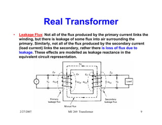
• Impedance Transfer:
To model a transformer, it is important to understand how impedance are
transferred from one side to another, that is primary to secondary or
secondary to primary. Impedance transfer helps to calculate the
current/voltage easier and get ride of the ratio for the rest of the calculation.
• Looking into the circuit from source side, let us define the impedance as
Zin = Vp/Ip
• Looking into the circuit from load side (neglecting the load itself), let us
define the impedance as ZL = Vs/Is
• Relating Vp/Ip in terms of Vs/Is using the turns ration, a,
[Vp/Ip]= a2 [Vs/Is]
Zin = a2 ZL
Hence, in general, any impedance transferred from secondary side to
primary side must be multiplied by the square of the turns-ratio, a2.
2/27/2007 ME 269 Transformer 11](https://image.slidesharecdn.com/chapter7transformers-141022021255-conversion-gate01/85/Chapter-7-transformers-11-320.jpg)
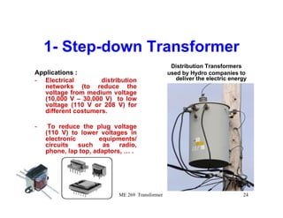
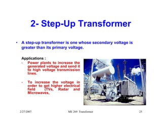

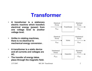
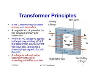
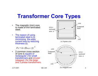
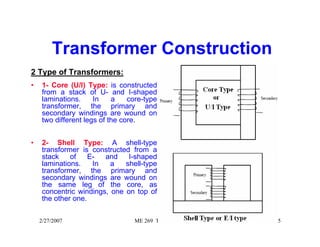
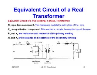
The document contains lecture notes about transformers. It discusses that a transformer transfers electrical energy from one voltage level to another without mechanical energy conversion. It has two circuits called primary and secondary linked by a magnetic circuit. An AC voltage applied to the primary induces a voltage in the secondary according to Faraday's law of induction. The core is made of laminated steel to reduce eddy current losses. Transformers can be of core type or shell type and are used to step up or step down voltages for applications like power distribution or electronics.