DETERMINATION OF VOLTAGE REGULATION METHOD OF SYNCHRONOUS MACHINE
The document discusses voltage regulation methods for synchronous generators, outlining definitions and three main techniques: synchronous impedance, magnetomotive force (mmf), and zero power factor methods. It details the process of determining voltage regulation using tests such as open-circuit and short-circuit tests, and includes calculations for parameters like armature resistance and synchronous reactance. Each method is explained with relevant equations and data requirements to provide a comprehensive understanding of voltage behavior in synchronous generators.
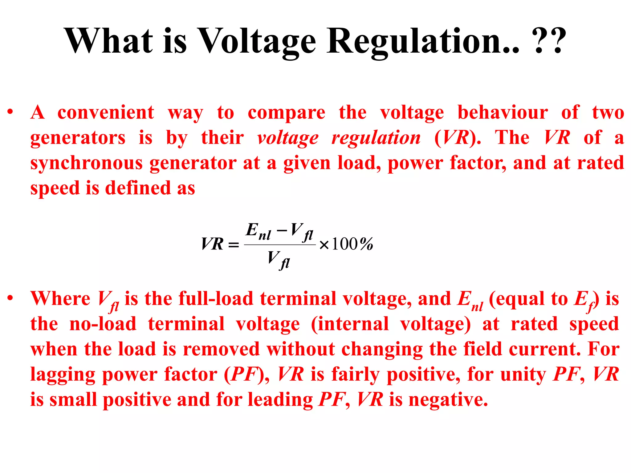
• A convenientway to compare the voltage behaviour of two
generators is by their voltage regulation (VR). The VR of a
synchronous generator at a given load, power factor, and at rated
speed is defined as
%
V
VE
VR
fl
flnl
100
• Where Vfl is the full-load terminal voltage, and Enl (equal to Ef) is
the no-load terminal voltage (internal voltage) at rated speed
when the load is removed without changing the field current. For
lagging power factor (PF), VR is fairly positive, for unity PF, VR
is small positive and for leading PF, VR is negative.
What is Voltage Regulation.. ??
4.
Voltage regulation bysynchronous
impedance method
To find the voltage regulation following data are
required:
I. Resistance of armature or stator winding per
phase
II. Open circuit characteristic
III.Short circuit characteristic.
5.
Resistance of armature
•The resistance of armature or stator winding per
phase can be determined by using voltmeter-
ammeter method or by using wheastone bridge.
• The effective stator winding resistance is always
greater than dc value due to skin effect.
• Ac resistance may be taken approximately 1.2 to
1.3 times the dc resistance measured.
6.
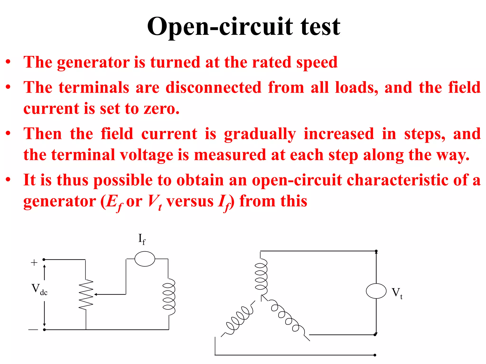
Open-circuit test
• Thegenerator is turned at the rated speed
• The terminals are disconnected from all loads, and the field
current is set to zero.
• Then the field current is gradually increased in steps, and
the terminal voltage is measured at each step along the way.
• It is thus possible to obtain an open-circuit characteristic of a
generator (Ef or Vt versus If) from this
+
Vdc
If
Vt
7.
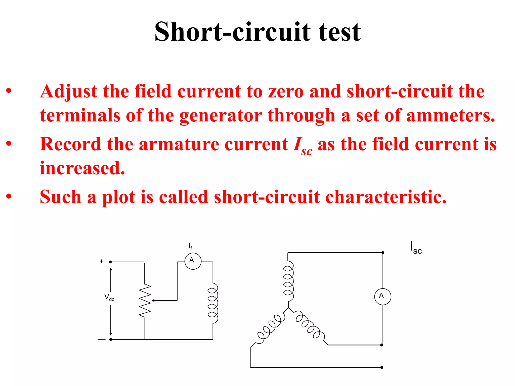
Short-circuit test
• Adjustthe field current to zero and short-circuit the
terminals of the generator through a set of ammeters.
• Record the armature current Isc as the field current is
increased.
• Such a plot is called short-circuit characteristic.
A
A+
Vdc
If Isc
8.
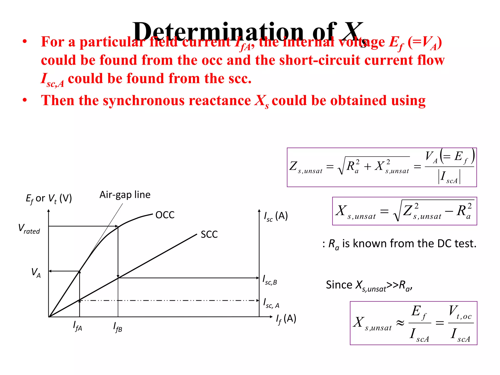
Determination of Xs•For a particular field current IfA, the internal voltage Ef (=VA)
could be found from the occ and the short-circuit current flow
Isc,A could be found from the scc.
• Then the synchronous reactance Xs could be obtained using
IfA
Ef or Vt (V) Air-gap line
OCC Isc (A)
SCC
If (A)
Vrated
VA
Isc,B
Isc, A
IfB
scA
fA
unsat,saunsat,s
I
EV
XRZ
22
22
aunsat,sunsat,s RZX
scA
oc,t
scA
f
unsat,s
I
V
I
E
X
: Ra is known from the DC test.
Since Xs,unsat>>Ra,
9.
Example
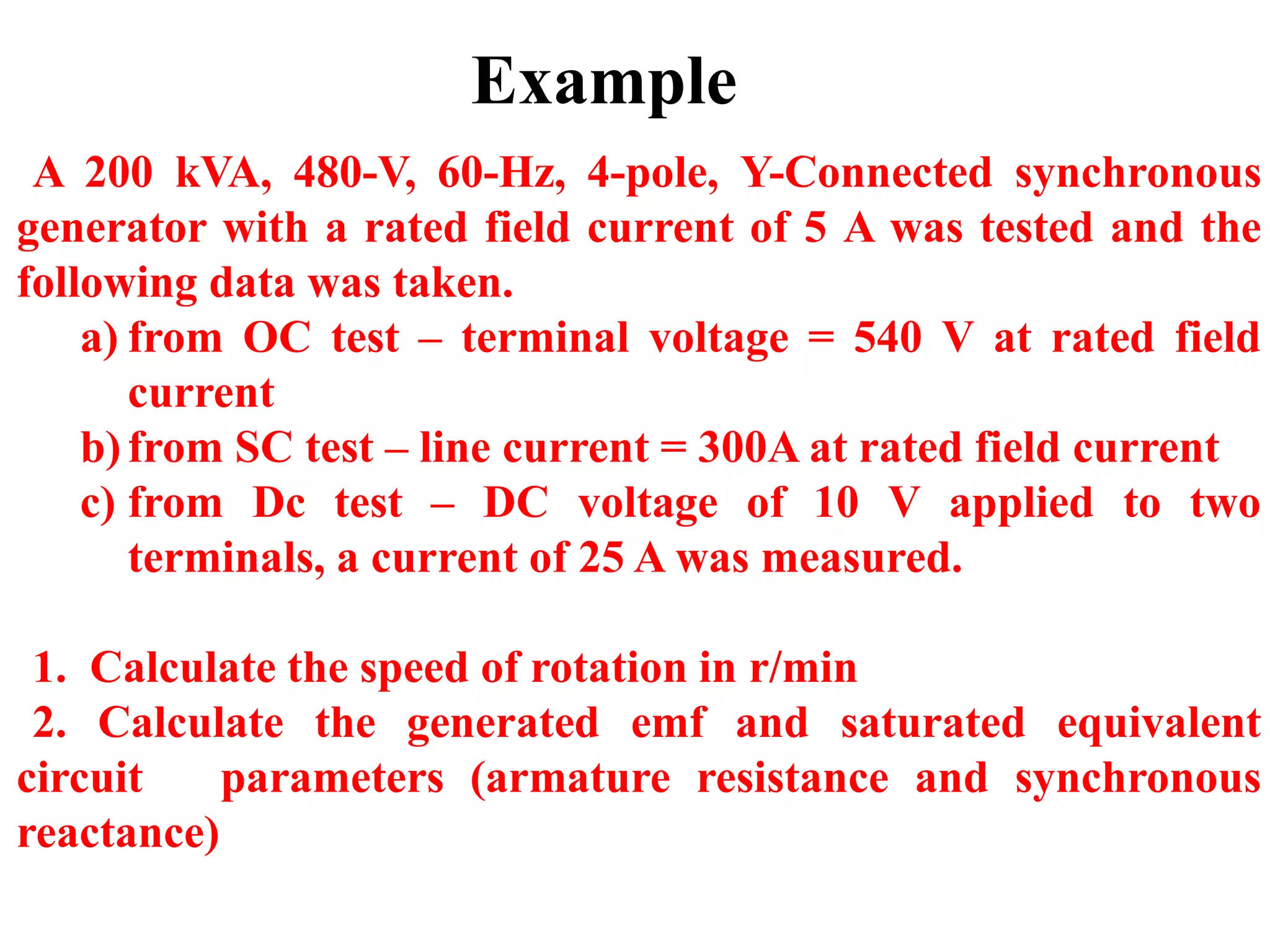
A 200 kVA,480-V, 60-Hz, 4-pole, Y-Connected synchronous
generator with a rated field current of 5 A was tested and the
following data was taken.
a) from OC test – terminal voltage = 540 V at rated field
current
b)from SC test – line current = 300A at rated field current
c) from Dc test – DC voltage of 10 V applied to two
terminals, a current of 25 A was measured.
1. Calculate the speed of rotation in r/min
2. Calculate the generated emf and saturated equivalent
circuit parameters (armature resistance and synchronous
reactance)
10.
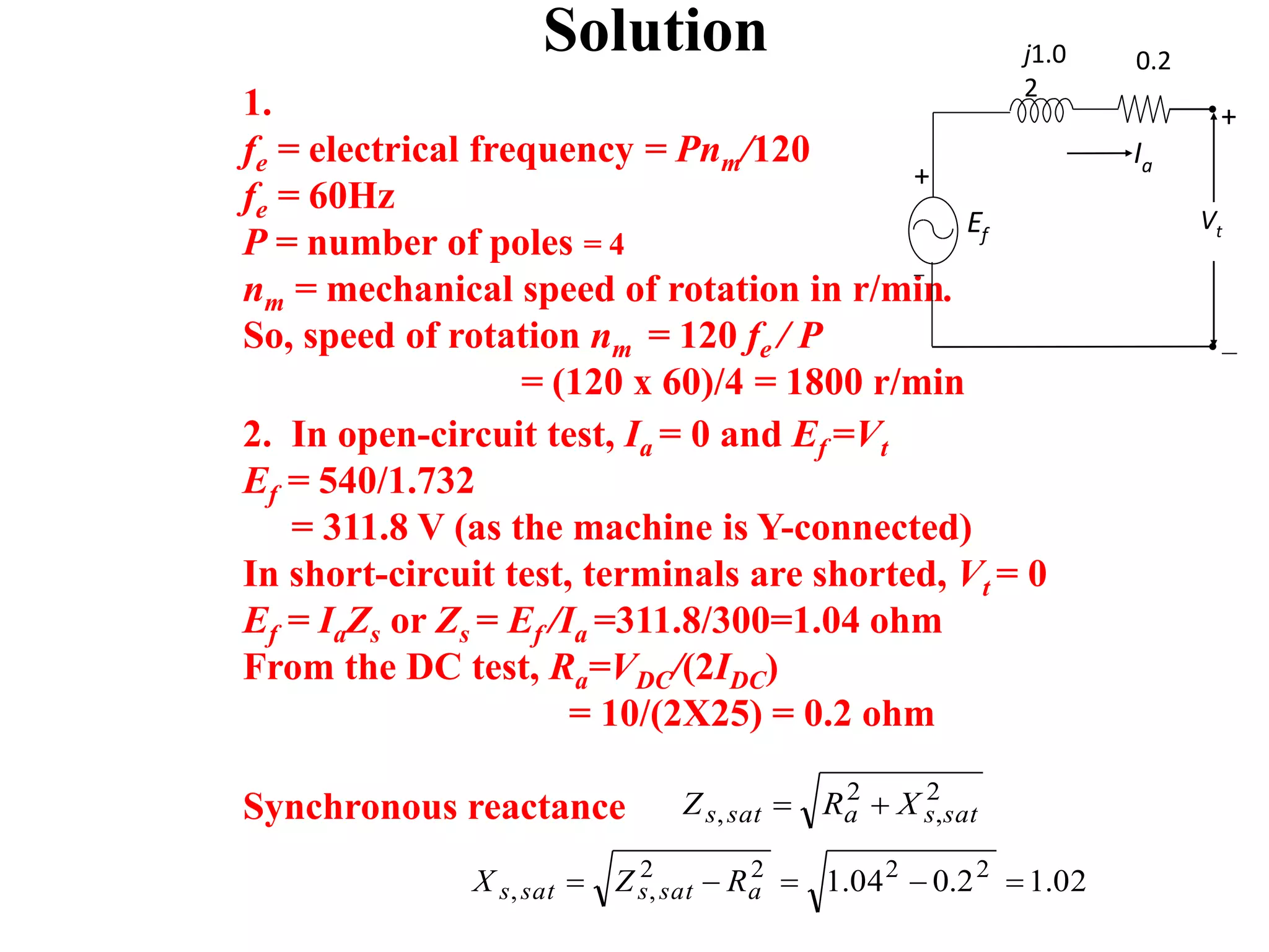
Solution
1.
fe = electricalfrequency = Pnm/120
fe = 60Hz
P = number of poles = 4
nm = mechanical speed of rotation in r/min.
So, speed of rotation nm = 120 fe / P
= (120 x 60)/4 = 1800 r/min
2. In open-circuit test, Ia = 0 and Ef =Vt
Ef = 540/1.732
= 311.8 V (as the machine is Y-connected)
In short-circuit test, terminals are shorted, Vt = 0
Ef = IaZs or Zs = Ef /Ia =311.8/300=1.04 ohm
From the DC test, Ra=VDC/(2IDC)
= 10/(2X25) = 0.2 ohm
Synchronous reactance 2
,
2
, satsasats XRZ
02.12.004.1 2222
,, asatssats RZX
Ia
Ef
Vt
j1.0
2
0.2
+
+
11.
Voltage regulation byMMF (Magnetomotive
Force) Method
• This method is also called Ampere-turn method
• This method is based on the results of open & short circuit
tests on an alternator
• For an alternator, the field MMF is required to produce the
normal voltage V on full load is the vector sum of the
following
1) Field MMF required to produce rated terminal voltage on
no-load
2) Field MMF required to neutralize the demagnetizing effect
of armature reaction on full load
12.
• On shortcircuit condition, the field MMF required to
produce full load current balances the impedance drop &
armature reaction.
• But since Ra & XL are very small due to S.C ,the impedance
drop can be neglected.
• Hence Power factor on S.C is almost zero lagging & the field
MMF are used completely to overcome the demagnetizing
effect of armature reaction.
• Therefore the demagnetizing armature MMF on full load are
equal & opposite to the field MMF required to produce Full
load current on S.C.
•
13.
Procedure to drawphasor diagram
for finding voltage regulation
Field Current required to produce rated terminal
voltage V obtained from O.C.C . This is denoted
by Ifo.
Field Current required to circulate full load
current obtained from S.C.C . This is denoted by
Ifa.
If the alternator is supplying full load then the
total MMF Is the vector sum of Ifo & Ifa.
14.
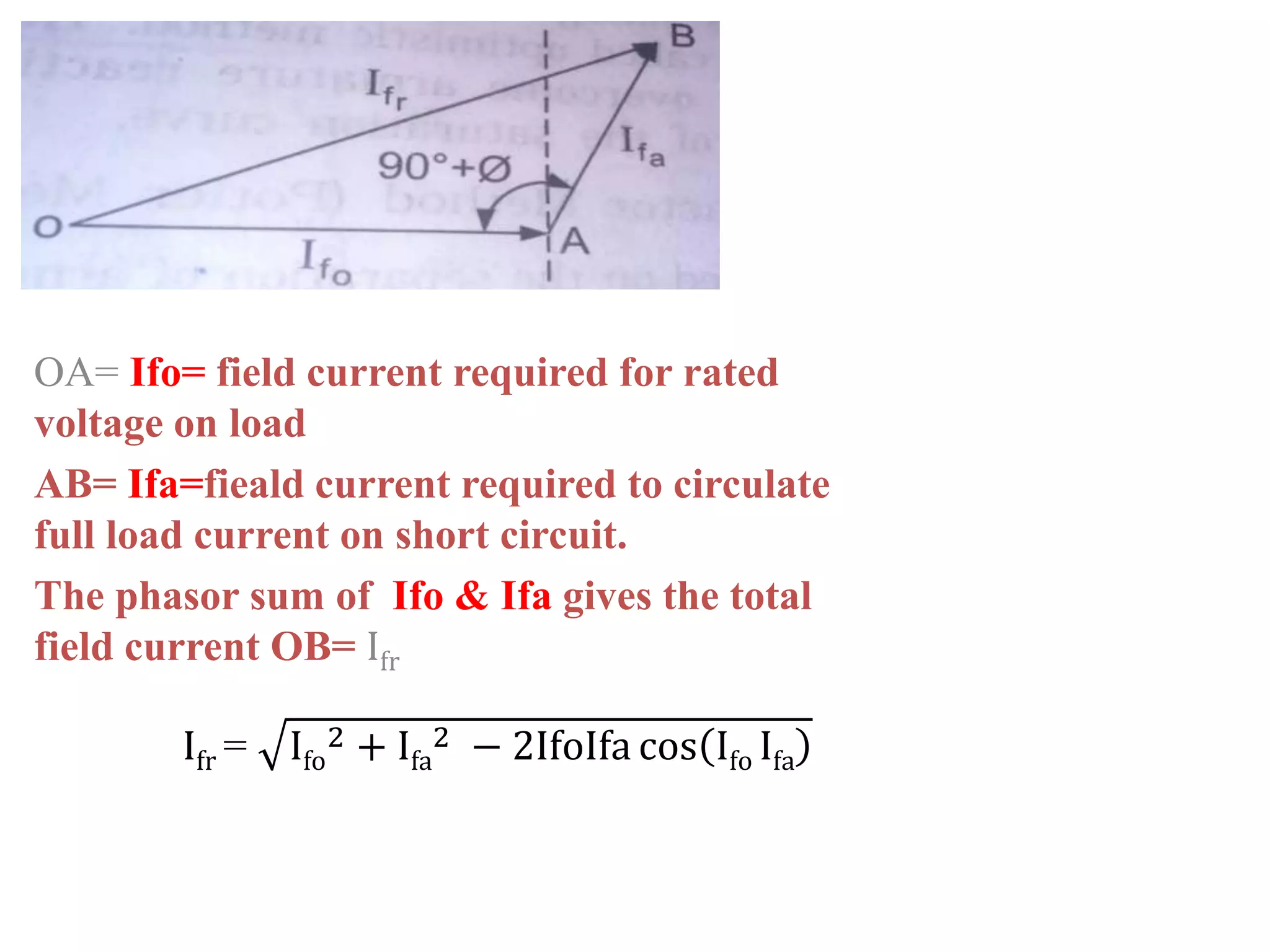
OA= Ifo= fieldcurrent required for rated
voltage on load
AB= Ifa=fieald current required to circulate
full load current on short circuit.
The phasor sum of Ifo & Ifa gives the total
field current OB= Ifr
Ifr = Ifo
2 + Ifa
2 − 2IfoIfa cos Ifo Ifa
15.
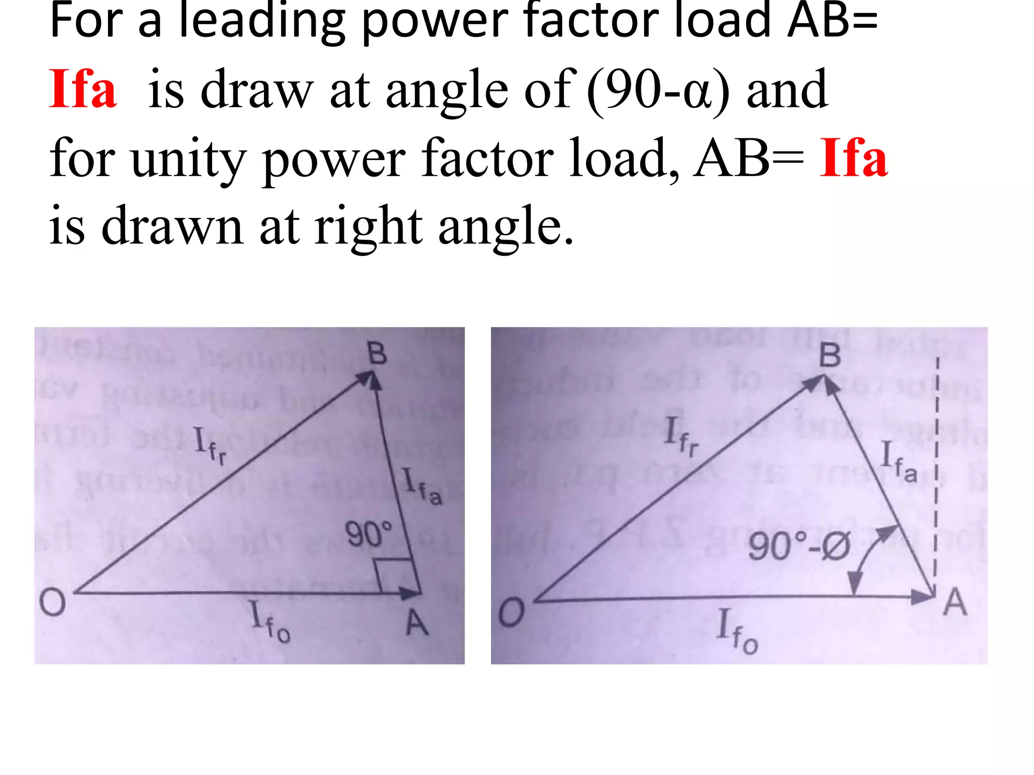
For a leadingpower factor load AB=
Ifa is draw at angle of (90-α) and
for unity power factor load, AB= Ifa
is drawn at right angle.
16.
Zero power factormethod
• This method is based on the separation of armature
leakage reactance drop & armature reaction effects.
• In this method, the armature leakage reactance XL is
called potier reactance.
•
• The following experimental data is required to
determine the regulation by this method
• Resistance of armature or stator winding per phase
• Open circuit characteristics (No load curve)
• Zero power factor curve (Z.P.F full-load curve)
17.
• Z.P.F isthe curve between terminal voltage &
excitation when the armature is delivering full-
load current at zero power factor while the
machine is running at synchronous speed.
• Z.P.F full load curve can be obtained:
• By loading the alternator with highly inductive
load & the field current corresponding to full-load
armature current at zero p.f and rated voltage is
noted.
• Field current corresponding to rated current
under short circuit test is noted.
18.
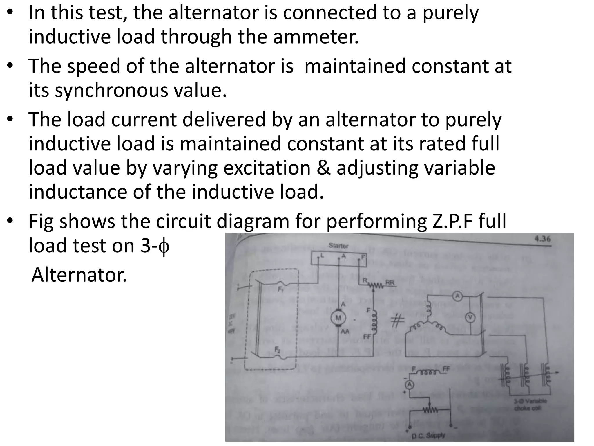
• In thistest, the alternator is connected to a purely
inductive load through the ammeter.
• The speed of the alternator is maintained constant at
its synchronous value.
• The load current delivered by an alternator to purely
inductive load is maintained constant at its rated full
load value by varying excitation & adjusting variable
inductance of the inductive load.
• Fig shows the circuit diagram for performing Z.P.F full
load test on 3-
Alternator.
19.
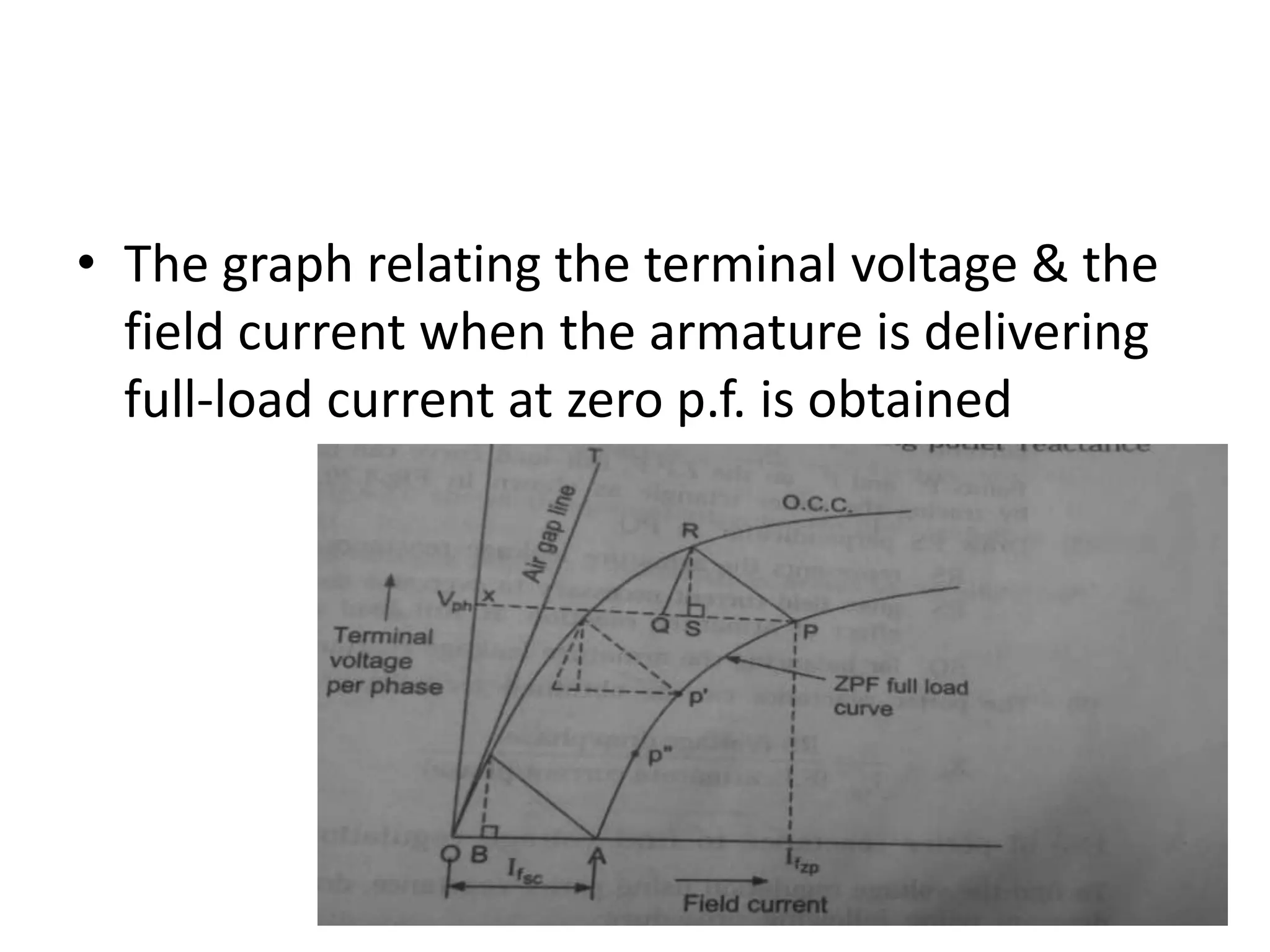
• The graphrelating the terminal voltage & the
field current when the armature is delivering
full-load current at zero p.f. is obtained
20.
• 1)First ofall, draw the o.c.c. (open circuit terminal voltage /phase versus filed
current ) and also draw the air gape line, a line which is tangent to O.C.C.(no—load
curve)
• 2) Draw the field current OA corresponding to full-load armature current on short
circuit.
Point a is obtained from a short circuit test with full load armature current.
hence OA represents the field current required to overcome
demagnetizing effect of armature reaction and to balance leakage r
eactance drop at full-load.
• 3) Draw the field current, If Ifzp at rated voltage (line XP) which corresponding to
full-load armature current at zero p.f., thus obtaining a point P on the Z.P.F full-
load curve.
Point P is the field current corresponding to f.l. armature current at zero p.f
Fig shows the Z.P.F full load characteristic of alternator.
• 4) from point P.PQ is drawn equal to and characteristic of alternator. Q,QR is drawn
parallel to tangent (air gap line).hence point R is obtained on no-load curve, which
corresponds to point P on full-load Z.P.F curve.
21.
• Joint Rto P. now PQR is a triangle. The triangle PQR is
called potier triangle. This triangle is constant for a given
armature current.
• Point p’ and p on the Z.P.F. full-load curve can be obtained
by tracing the potier triangle as shown in fig.
• 5) draw RS perpendicular to PQ.
• RS represents the armature leakage reactance drop(IXL).
• PS gives field current necessary to overcome
demagnetizing effect of armature reaction at full load
and
• SQ for balancing the armature leakage reactance drop RS.