Download to read offline
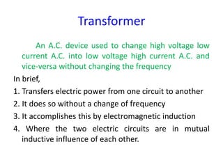
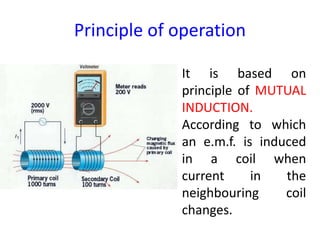
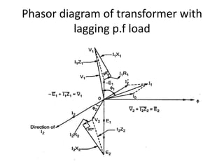
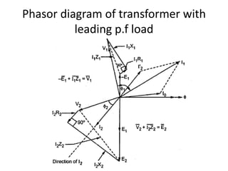
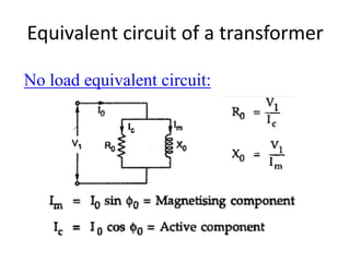
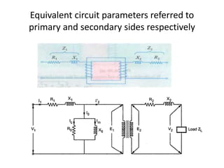
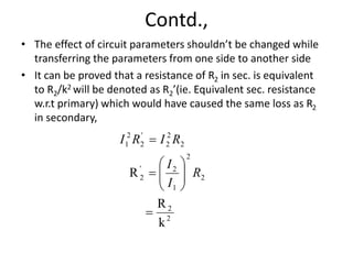
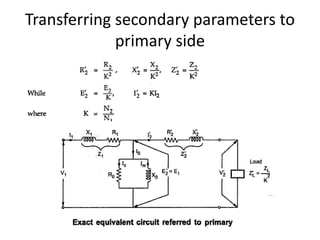
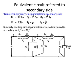
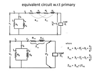
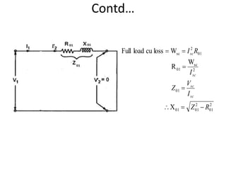
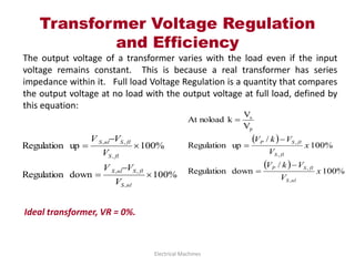
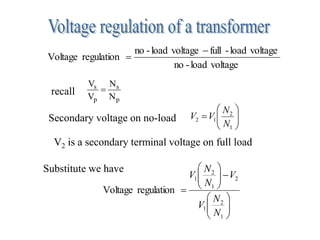
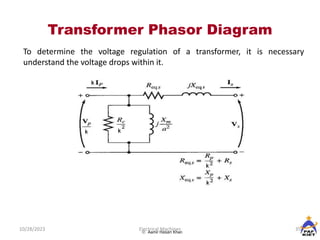
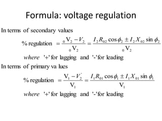
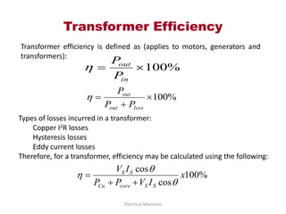
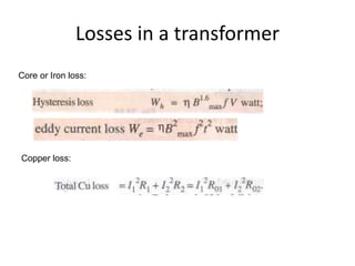
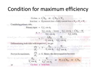

The document discusses transformers, devices that convert voltages while maintaining frequency through electromagnetic induction. It details their construction, operation, ideal characteristics, and testing methods to evaluate performance, such as open-circuit and short-circuit tests. Additionally, it covers voltage regulation, efficiency calculations, and the types of losses transformers incur.