This document discusses different types of transformers and their working principles. It describes:
1. There are two main types of transformers based on their construction - core type and shell type. Core type transformers have half of each winding around each core limb, while shell type transformers place both windings around the central limb.
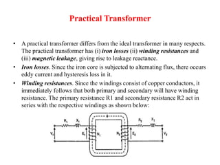
2. Transformers work on the principle of mutual induction between windings. An alternating voltage applied to the primary induces an emf in the secondary according to Faraday's law of induction.
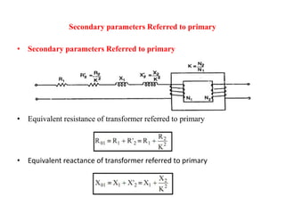
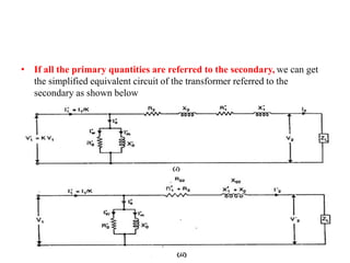
3. Key transformer concepts discussed include the voltage transformation ratio, ideal transformers, equivalent circuits, transformer tests like open-circuit and short-circuit tests to determine losses and efficiency.