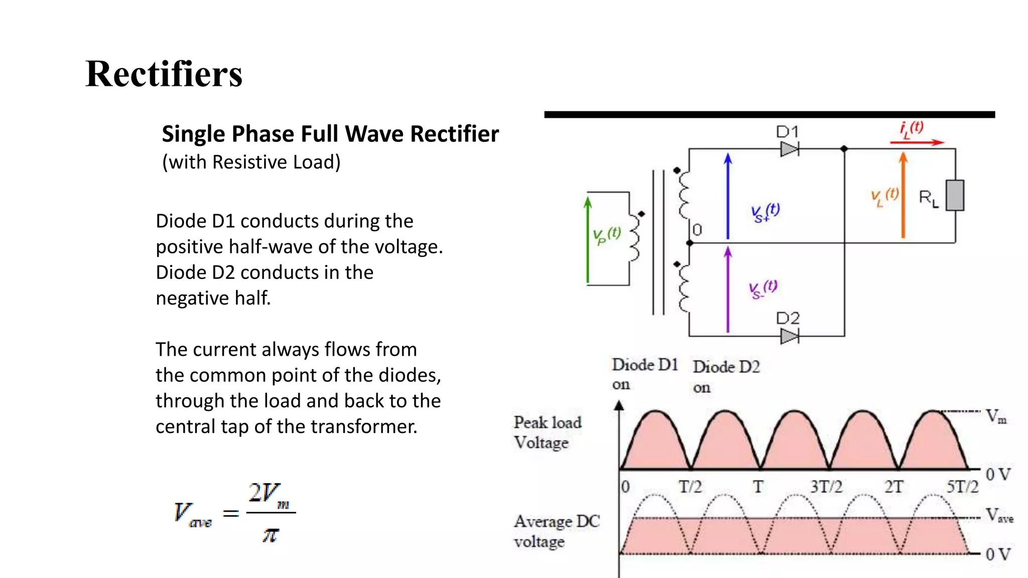
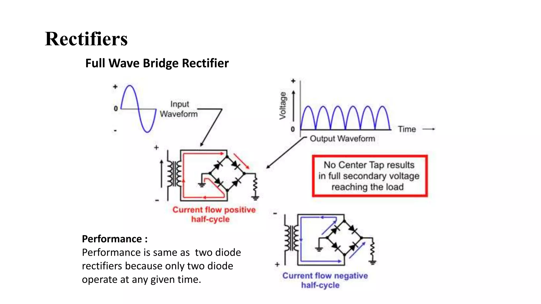
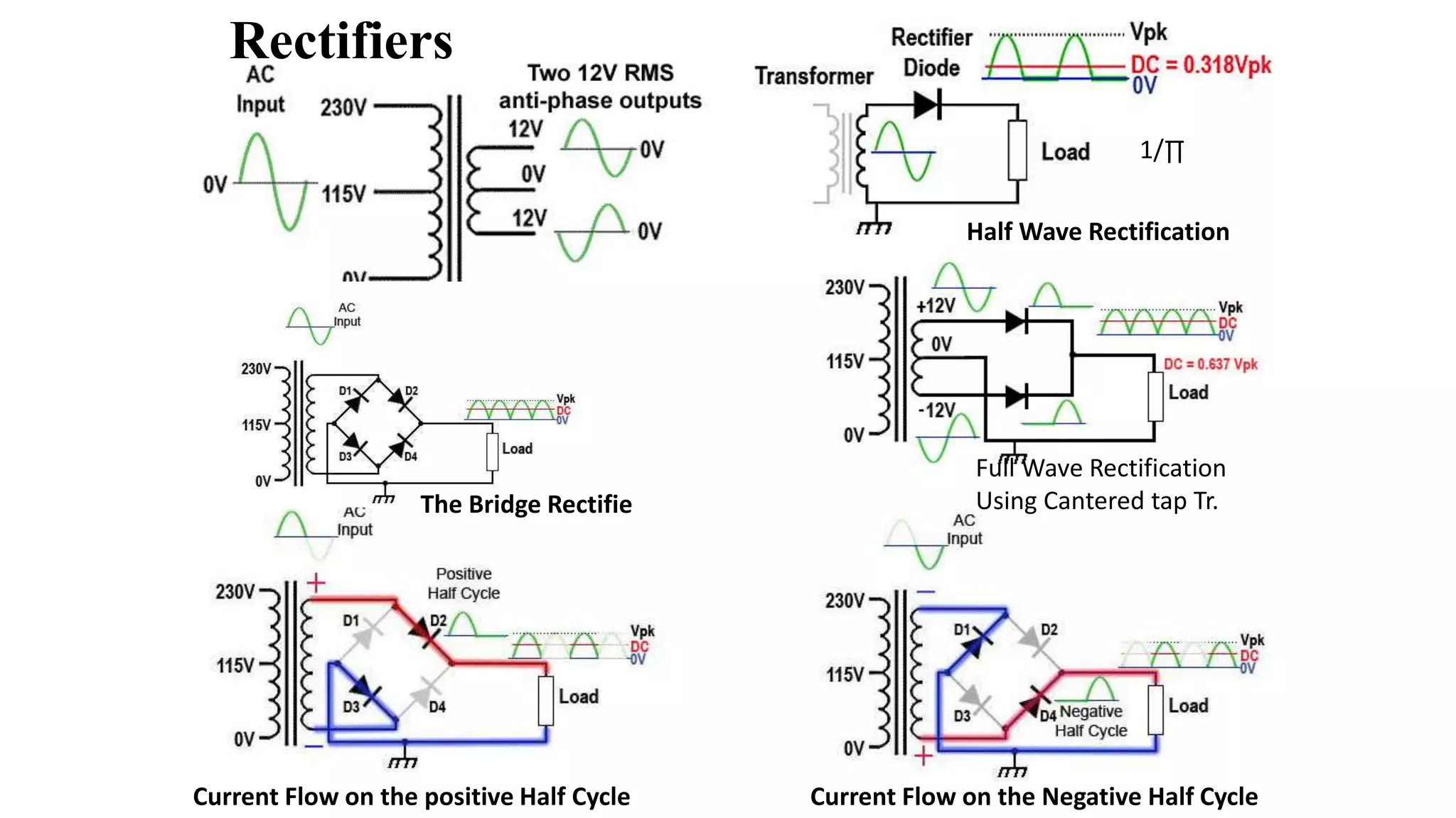
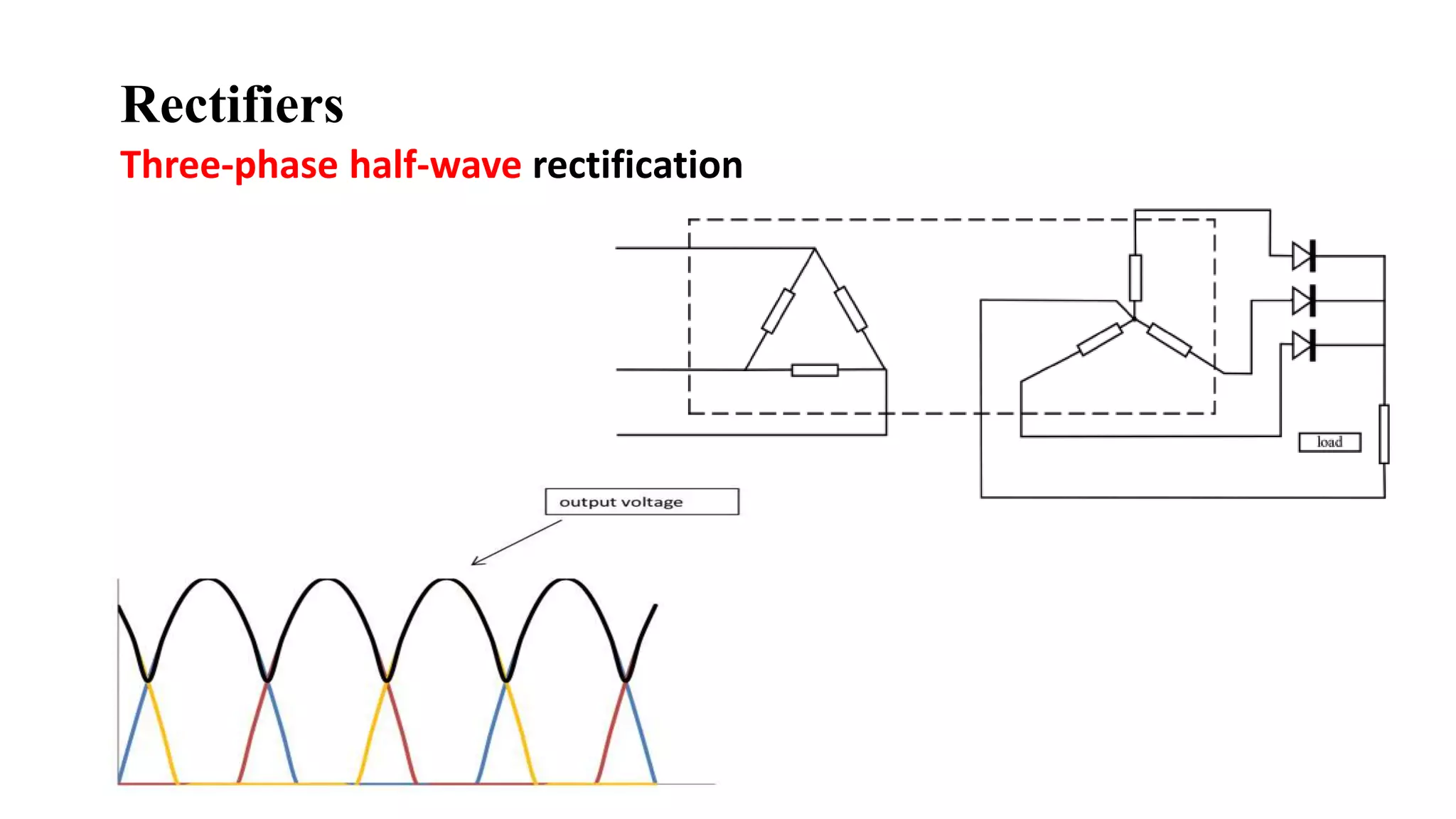
Power Electronics
EE 368 Lecture-3
These slides are compiled from the material collected from the text book and web resources:
Rectifiers
Topics
Diode Rectifiers
Controlled Rectifiers
Rectifier Performance Parameters
All quadrant operation of single-phase controlled rectifiers
Three-phase rectifiers
Application: Single-phase controlled rectifiers Battery Charger
Diode Rectifiers with R and RL Loads.
Classification of Rectifiers
Rectifiers
AC to DC Convertors
Uncontrolled Rectifiers
Rectifiers based upon Diodes, stop conducting due to natural Commutation
Controlled Rectifiers
Rectifiers based upon Thrystor, stop conducting due to natural/ forced Commutation
A rectifier convert AC supply into unidirectional DC supply.
Alternating Sinusoidal Waveform
𝑉𝑎𝑣𝑔 = 0.636 𝑉𝑝𝑘
𝑉𝑟𝑚𝑠 = 0.707 𝑉𝑝𝑘
Line voltages measured
from Wall socket:
220 VRMS = 311V Vp-p
AC to DC conversion
Rectifiers
Single Phase Half Wave Rectifier
(with Resistive Load)
Rectifiers
Voltage
Load Current
Resistive load
V = IR
Rectifiers
Single phase diode rectifiers (p = 1)
Diode D1 conducts during the
positive half-wave of the voltage.
Diode D2 conducts in the
negative half.
The current always flows from
the common point of the diodes,
through the load and back to the
central tap of the transformer.
Single Phase Full Wave Rectifier
(with Resistive Load)
Rectifiers
Single Phase Full Wave Rectifier
(with Resistive Load)
Full Wave Center-tapped Rectifier
Rectifiers
The output voltage varies between the peak voltage Vm and zero
in each cycle.
This variation is called “ripple”, and the corresponding voltage
is called the peak-to-peak ripple voltage, Vp-p.
Ripple % = (Vp-p/Vavg) x 100
Simple Examples
In the full-wave rectifier circuit, the transformer has a turns ratio of 1:2. The transformer primary
winding is connected across an AC source of 230V (rms), 50 Hz. The load resistor is 50Ω. For this circuit,
determine the DC output voltage, peak-to-peak ripple in the output voltage, and output ripple frequency.
Example:
Solution:
Ripple % = (Vp-p/Vavg) x 100
= (325.3/207) x 100 =157
Full Wave Bridge Rectifier
Performance :
Performance is same as two diode
rectifiers because only two diode
operate at any given time.
Rectifiers
Current Flow on the Negative Half CycleCurrent Flow on the positive Half Cycle
The Bridge Rectifie
Full Wave Rectification
Using Cantered tap Tr.
Half Wave Rectification
Rectifiers
1/∏
These parameters are needed to compare the performances
among the different rectifiers architectures.
Generic scheme of a rectifier
Vp: Input of the AC voltages feed into the
transformer
Vs: Secondary of the transformer feed into
rectifier/rectifiers.
VL: Voltage output of the rectifier supplied to
load.
Assume:
Ideal switches (diodes or
thyristors) with zero commutation
time
Zero on-resistance (i.e., when
conducting they present neither
voltage drop nor losses).
The load itself is an ideal
resistance.
Commutation is the process by which we can turn OFF a thyristor.
So the process of switching OFF a thyristor or SCR is known as
Commutation.
Performance parameters
Rectifiers
The DC voltage on the load is
the average over the period T
of the output voltage of the
rectifier:
Generic Rectifiers
Similarly, it is possible to
define the r.m.s. voltage on
the load:
The ratio of the two voltages is the Form
Factor (FF):
This parameter is quite important
since it is an index of the efficiency of
the rectification process.
1. Form Factor (FF):
r.m.s. voltage on the load
The DC voltage or Vavg
Assumed the load is purely resistive
Performance parameters
Vrms =
=VL
Rectifiers
By assuming the load to be purely
resistive:
The rectification ratio (η), also known
as rectification efficiency:
Where:
OR
OR
FOR ideal switches, with no losses: RD = 0
The Ripple Factor (RF) is another important
parameter used to describe the quality of the
rectification.
It represents the smoothness of the voltage
waveform at the output of the rectifier
3. Ripple Factor (RF)
2. Efficiency:
V = IR
η = Pdc / Pac
Pac =Irms
2 (rf +
RL)
Pdc = Idc
2 RL
Performance parameters
This parameter characterized the ratio between the average power and
transformer secondary ( source) volt-ampere rating ( VA) rating.
Transformer Utilization Factor (TUF):
Where (VA)rating= Vs.Is,
Vs= the secondary ( source) rms voltage,
Is=IRMS : the secondary rms current .
This characterized the ratio between average output power
and the appearance power energized the system (transformer,
rectifier, and load):
Performance parameters
Where: VAP and VAS are the
power ratings at the primary and
secondary of the transformer
The Crest factor:
This parameter defines the measure of the peak
input current (IS)peak as compared with its rms
value IS:
Is1 is the rms value of fundamental component of the
input current. Is rms value of input current.
Input Power Factor:
φ : angle between the fundamental components of
voltage and current. It’s called displacement angle
Displacement factor
Half-wave rectifier
From physics point of view:
The ideal power converter is the one that supplies the best direct current to the load
Should have very low ripple factor
Should very high stability,
Simplest structure. Only one diode is
placed at the secondary of the
transformer.
the rectification process occurs
only during half-periods.
Load current iL(t) always circulates in
the secondary winding in the same
direction.
Single phase Half Wave Rectifier with Resistive Load
Using equation from last slide:
Waveforms of the single-phase, single-way, half-wave rectifier
And, similarly,
The rectification process occurs only during the half-periods.
Vavg = = 0.318 Vs
0.5 VsVrms =
Determine:
1- the average and
rms voltage and
current
2- the efficiency,
TUF,
3- FF, RF, and the
peak reverse
voltage across the
diode (PIV).
4- the CF, and the
input PF.
Single phase rectifier has a purely resistive load of 10Ω, energized by voltage source of 220V
throughout two windings transformer with ratio 2:1.
Example:
Cont..
1. Low ( poor) transform utilization 28.6%, which means that the transformer must be 1/0.286=3.49 times
larger that when it is used to deliver power from a pure ac voltage.
2. Low ( poor) rectification efficiency = 40.5%
3. Presence of current dc component in the secondary current causing additional losses ( winding and core
heating).
4. High ripples 121% greater than that when the source is pure dc
5. High ripple factor, which means that a filter with large capacitance is required for smoothing the output
voltage, therefore this yield high capacitor starting current problem.
Therefore this rectifier configuration is rarely used due to the weakness in quality of it's power and
signal parameters.
Comments:
Analyzing these rectifier parameters one can easily conclude the followings:
Single Phase rectifier with Resistance
and Inductance Combined Load
Low frequency High frequency
Short Circuit Open Circuit
The phase difference is = 90 degrees., with voltage leads the current. This leads to a
positive phase for inductive circuits since current lags the voltage in
Voltage and Current relationship in
an Inductor
Voltages and current in Inductive Load
AC circuit with a load consisting of
both inductance and resistance
If it was only R load
I =E/R = 120v/60 Ω
I = 2 Amp
Single phase diode rectifiers (p = 1)
With RL Load
Voltage
Voltage
Current
Current
R+L+D0 load
R+L load
-Ve due to L
I due to Diode
Waveforms of the single-phase, full-wave rectifier
Rectifiers
Performance Half wave Full Wave
FF 1.571 1.11
η 0.405 0.81
RF 1.21 0.483
Find the performance of the Full wave rectifier shown below that is designed to be
used at home to drive 200 Ω resistive load.(use ideal diodes)
Example:
Form Factor
Efficiency
Ripple Factor
Other important parameters
5:1
Three-phase half-wave rectification
Rectifiers
Rectifiers
Three-phase full-
wave bridge rectifier
6- pulse double star rectifier. Output waveform : 6- pulse double star rectifier.
6- pulse double star rectifier.
Rectifiers
Star-Delta 12-pulse bridge rectifier
360/12 Each phase is 30* apart
Rectifiers
Performance parameters for some
multi-phase topologies
Topologies:
The study of geometrical properties and spatial relations unaffected by
the continuous change of shape or size of figures
Increasing the number of phases in a multi-phase, single-way rectifier, the
result of the rectification is improved
For an uncontrolled three-phase bridge rectifier, six diodes are used, and the circuit
again has a pulse number of six. For this reason, it is also commonly referred to as a
six-pulse bridge.
Six-pulse diode bridge rectifier
Application
Automobile Power Generator/Alternator
Controlled Rectifiers
dc
Single phase controlled
rectifier with resistive load
Voltages across SCR
Voltages across LOAD
Current through the LOAD
cos 0 = 1
Source Voltages
Rectifiers
Single Phase Half
Controlled Rectifiers
• During the positive half cycle of the input,
T1 and D2 are forward biased.
• When T1 is fired, then the load current
flows through T1 and D2 to ground.
• Now the voltage passes through negative
going zero crossing of the input voltage, D4
comes into conduction by commutating D2
and then the load voltage becomes zero
Positive half cycle of the
input
Rectifiers
• During the negative
half cycle, T3 and D4
are forward biased.
Negative half cycle
Single Phase Half Controlled
Rectifiers
• When T3 is triggered
load current start
flowing through T3
and D4 to lower
potential.
Single phase half wave Single phase full wave
Rectifiers
Single Phase Fully Controlled Rectifier
Complete control on negative and
positive half cycle of the input
• During the positive half cycle of the
input signal T1 and T2 are forward
biased and when these are triggered or
fired these are starts conducting so that
load current flow through them.
Working of fully controlled full wave rectifier
• During the negative half cycle of the input AC, T3 and T4 are in the forward
blocking state and when a gate pulse is applied to them, they will turn ON and
load current starts flowing through them
• At the same time, across T1 and T2 a negative voltage causes to the commutation of
these thyristors immediately.
Rectifiers
Circuit Diagram: RC Triggering Circuit:
Single phase full wave controlled rectifier
Voltages
Wave shapes
at different
points
RC Triggering
Circuit:
In the previous example the operation is performed in four quadrantes:
I- half cycle 0 < α < ∏
II- half cycle ∏< α <2∏
III- half cycle 2∏< α <3∏
IV- Half cycle 3∏< α < 4∏
All quadrant operation of single-
phase controlled rectifiers
The End

Rectifiers (ac dc)

  • 1.
    Power Electronics EE 368Lecture-3 These slides are compiled from the material collected from the text book and web resources: Rectifiers
  • 2.
    Topics Diode Rectifiers Controlled Rectifiers RectifierPerformance Parameters All quadrant operation of single-phase controlled rectifiers Three-phase rectifiers Application: Single-phase controlled rectifiers Battery Charger Diode Rectifiers with R and RL Loads.
  • 3.
  • 4.
    Rectifiers AC to DCConvertors Uncontrolled Rectifiers Rectifiers based upon Diodes, stop conducting due to natural Commutation Controlled Rectifiers Rectifiers based upon Thrystor, stop conducting due to natural/ forced Commutation
  • 5.
    A rectifier convertAC supply into unidirectional DC supply. Alternating Sinusoidal Waveform 𝑉𝑎𝑣𝑔 = 0.636 𝑉𝑝𝑘 𝑉𝑟𝑚𝑠 = 0.707 𝑉𝑝𝑘 Line voltages measured from Wall socket: 220 VRMS = 311V Vp-p AC to DC conversion Rectifiers
  • 6.
    Single Phase HalfWave Rectifier (with Resistive Load) Rectifiers
  • 7.
    Voltage Load Current Resistive load V= IR Rectifiers Single phase diode rectifiers (p = 1)
  • 8.
    Diode D1 conductsduring the positive half-wave of the voltage. Diode D2 conducts in the negative half. The current always flows from the common point of the diodes, through the load and back to the central tap of the transformer. Single Phase Full Wave Rectifier (with Resistive Load) Rectifiers
  • 9.
    Single Phase FullWave Rectifier (with Resistive Load) Full Wave Center-tapped Rectifier Rectifiers The output voltage varies between the peak voltage Vm and zero in each cycle. This variation is called “ripple”, and the corresponding voltage is called the peak-to-peak ripple voltage, Vp-p. Ripple % = (Vp-p/Vavg) x 100
  • 10.
  • 11.
    In the full-waverectifier circuit, the transformer has a turns ratio of 1:2. The transformer primary winding is connected across an AC source of 230V (rms), 50 Hz. The load resistor is 50Ω. For this circuit, determine the DC output voltage, peak-to-peak ripple in the output voltage, and output ripple frequency. Example: Solution: Ripple % = (Vp-p/Vavg) x 100 = (325.3/207) x 100 =157
  • 12.
    Full Wave BridgeRectifier Performance : Performance is same as two diode rectifiers because only two diode operate at any given time. Rectifiers
  • 13.
    Current Flow onthe Negative Half CycleCurrent Flow on the positive Half Cycle The Bridge Rectifie Full Wave Rectification Using Cantered tap Tr. Half Wave Rectification Rectifiers 1/∏
  • 14.
    These parameters areneeded to compare the performances among the different rectifiers architectures. Generic scheme of a rectifier Vp: Input of the AC voltages feed into the transformer Vs: Secondary of the transformer feed into rectifier/rectifiers. VL: Voltage output of the rectifier supplied to load. Assume: Ideal switches (diodes or thyristors) with zero commutation time Zero on-resistance (i.e., when conducting they present neither voltage drop nor losses). The load itself is an ideal resistance. Commutation is the process by which we can turn OFF a thyristor. So the process of switching OFF a thyristor or SCR is known as Commutation. Performance parameters Rectifiers
  • 15.
    The DC voltageon the load is the average over the period T of the output voltage of the rectifier: Generic Rectifiers Similarly, it is possible to define the r.m.s. voltage on the load: The ratio of the two voltages is the Form Factor (FF): This parameter is quite important since it is an index of the efficiency of the rectification process. 1. Form Factor (FF): r.m.s. voltage on the load The DC voltage or Vavg Assumed the load is purely resistive Performance parameters Vrms = =VL Rectifiers
  • 16.
    By assuming theload to be purely resistive: The rectification ratio (η), also known as rectification efficiency: Where: OR OR FOR ideal switches, with no losses: RD = 0 The Ripple Factor (RF) is another important parameter used to describe the quality of the rectification. It represents the smoothness of the voltage waveform at the output of the rectifier 3. Ripple Factor (RF) 2. Efficiency: V = IR η = Pdc / Pac Pac =Irms 2 (rf + RL) Pdc = Idc 2 RL Performance parameters
  • 17.
    This parameter characterizedthe ratio between the average power and transformer secondary ( source) volt-ampere rating ( VA) rating. Transformer Utilization Factor (TUF): Where (VA)rating= Vs.Is, Vs= the secondary ( source) rms voltage, Is=IRMS : the secondary rms current . This characterized the ratio between average output power and the appearance power energized the system (transformer, rectifier, and load): Performance parameters Where: VAP and VAS are the power ratings at the primary and secondary of the transformer
  • 18.
    The Crest factor: Thisparameter defines the measure of the peak input current (IS)peak as compared with its rms value IS: Is1 is the rms value of fundamental component of the input current. Is rms value of input current. Input Power Factor: φ : angle between the fundamental components of voltage and current. It’s called displacement angle Displacement factor
  • 19.
    Half-wave rectifier From physicspoint of view: The ideal power converter is the one that supplies the best direct current to the load Should have very low ripple factor Should very high stability, Simplest structure. Only one diode is placed at the secondary of the transformer. the rectification process occurs only during half-periods. Load current iL(t) always circulates in the secondary winding in the same direction. Single phase Half Wave Rectifier with Resistive Load
  • 20.
    Using equation fromlast slide: Waveforms of the single-phase, single-way, half-wave rectifier And, similarly, The rectification process occurs only during the half-periods. Vavg = = 0.318 Vs 0.5 VsVrms =
  • 21.
    Determine: 1- the averageand rms voltage and current 2- the efficiency, TUF, 3- FF, RF, and the peak reverse voltage across the diode (PIV). 4- the CF, and the input PF. Single phase rectifier has a purely resistive load of 10Ω, energized by voltage source of 220V throughout two windings transformer with ratio 2:1. Example: Cont..
  • 23.
    1. Low (poor) transform utilization 28.6%, which means that the transformer must be 1/0.286=3.49 times larger that when it is used to deliver power from a pure ac voltage. 2. Low ( poor) rectification efficiency = 40.5% 3. Presence of current dc component in the secondary current causing additional losses ( winding and core heating). 4. High ripples 121% greater than that when the source is pure dc 5. High ripple factor, which means that a filter with large capacitance is required for smoothing the output voltage, therefore this yield high capacitor starting current problem. Therefore this rectifier configuration is rarely used due to the weakness in quality of it's power and signal parameters. Comments: Analyzing these rectifier parameters one can easily conclude the followings:
  • 24.
    Single Phase rectifierwith Resistance and Inductance Combined Load Low frequency High frequency Short Circuit Open Circuit
  • 25.
    The phase differenceis = 90 degrees., with voltage leads the current. This leads to a positive phase for inductive circuits since current lags the voltage in Voltage and Current relationship in an Inductor
  • 26.
    Voltages and currentin Inductive Load
  • 27.
    AC circuit witha load consisting of both inductance and resistance If it was only R load I =E/R = 120v/60 Ω I = 2 Amp
  • 28.
    Single phase dioderectifiers (p = 1) With RL Load Voltage Voltage Current Current R+L+D0 load R+L load -Ve due to L I due to Diode
  • 29.
    Waveforms of thesingle-phase, full-wave rectifier Rectifiers Performance Half wave Full Wave FF 1.571 1.11 η 0.405 0.81 RF 1.21 0.483
  • 30.
    Find the performanceof the Full wave rectifier shown below that is designed to be used at home to drive 200 Ω resistive load.(use ideal diodes) Example: Form Factor Efficiency Ripple Factor Other important parameters 5:1
  • 31.
  • 32.
  • 33.
    6- pulse doublestar rectifier. Output waveform : 6- pulse double star rectifier. 6- pulse double star rectifier. Rectifiers
  • 34.
    Star-Delta 12-pulse bridgerectifier 360/12 Each phase is 30* apart Rectifiers
  • 35.
    Performance parameters forsome multi-phase topologies Topologies: The study of geometrical properties and spatial relations unaffected by the continuous change of shape or size of figures Increasing the number of phases in a multi-phase, single-way rectifier, the result of the rectification is improved
  • 36.
    For an uncontrolledthree-phase bridge rectifier, six diodes are used, and the circuit again has a pulse number of six. For this reason, it is also commonly referred to as a six-pulse bridge. Six-pulse diode bridge rectifier
  • 37.
  • 38.
  • 40.
  • 41.
    dc Single phase controlled rectifierwith resistive load Voltages across SCR Voltages across LOAD Current through the LOAD cos 0 = 1 Source Voltages
  • 42.
    Rectifiers Single Phase Half ControlledRectifiers • During the positive half cycle of the input, T1 and D2 are forward biased. • When T1 is fired, then the load current flows through T1 and D2 to ground. • Now the voltage passes through negative going zero crossing of the input voltage, D4 comes into conduction by commutating D2 and then the load voltage becomes zero Positive half cycle of the input
  • 43.
    Rectifiers • During thenegative half cycle, T3 and D4 are forward biased. Negative half cycle Single Phase Half Controlled Rectifiers • When T3 is triggered load current start flowing through T3 and D4 to lower potential.
  • 44.
    Single phase halfwave Single phase full wave
  • 45.
    Rectifiers Single Phase FullyControlled Rectifier Complete control on negative and positive half cycle of the input
  • 46.
    • During thepositive half cycle of the input signal T1 and T2 are forward biased and when these are triggered or fired these are starts conducting so that load current flow through them. Working of fully controlled full wave rectifier • During the negative half cycle of the input AC, T3 and T4 are in the forward blocking state and when a gate pulse is applied to them, they will turn ON and load current starts flowing through them • At the same time, across T1 and T2 a negative voltage causes to the commutation of these thyristors immediately.
  • 47.
  • 48.
    Circuit Diagram: RCTriggering Circuit: Single phase full wave controlled rectifier
  • 49.
  • 50.
    In the previousexample the operation is performed in four quadrantes: I- half cycle 0 < α < ∏ II- half cycle ∏< α <2∏ III- half cycle 2∏< α <3∏ IV- Half cycle 3∏< α < 4∏ All quadrant operation of single- phase controlled rectifiers
  • 51.