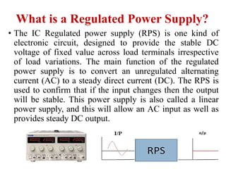
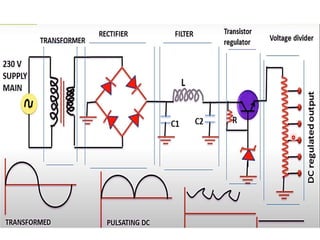
Medical electronic system
Regulated power supply
Assist Lecturer Hala Kamal
What is a Regulated Power Supply?
• The IC Regulated power supply (RPS) is one kind of
electronic circuit, designed to provide the stable DC
voltage of fixed value across load terminals irrespective
of load variations. The main function of the regulated
power supply is to convert an unregulated alternating
current (AC) to a steady direct current (DC). The RPS is
used to confirm that if the input changes then the output
will be stable. This power supply is also called a linear
power supply, and this will allow an AC input as well as
provides steady DC output.
The figure below shows the block diagram of a typical
regulated DC power supply.
The most important blocks of this system
are
1.Transformer
2.Rectifier
3.Filter
4.Regulator
Operation of Regulated Power
Supply
Transformer
The transformer is a device that transfers the electrical energy
from one circuit to another circuit by changing the voltage level.
in this circuit, a step-down transformer is used that is used to step
down the voltage. Generally, it takes the 220V supply as input
and provides 12V or 24V or 6V as the output according to the
circuit output requirement. By changing the turns ratio of the
transformer, the output voltage can be changed. The transformer
is not an essential part of a regulated power supply circuit, it is
only used when voltage steps down is required. If the output
230V DC supply is required, then there is no requirement for a
transformer.
Rectification
• Rectifier is an electronic circuit consisting of diodes
which carries out the rectification process.
Rectification is the process of converting an
alternating voltage or current into corresponding
direct (DC) quantity. The input to a rectifier is AC
whereas its output is unidirectional pulsating DC.
• Although a half wave rectifier could technically be
used, its power losses are significant compared to a
full wave rectifier. As such, a full wave rectifier or a
bridge rectifier is used to rectify both the half cycles
of the ac supply (full wave rectification). The figure
below shows a full wave bridge rectifier.
Filter Circuit
• The output of the rectifier circuit cannot provide the pure DC
supply. There are some ripple or AC components available in the
DC power supply. To remove those ripples or make the DC
supply pure, a filter circuit is used. The output of the rectifier is
connected to the input of the filter circuit. Generally, a pure
capacitor filter, LC filter, or pi filter is used. According to nature,
a capacitor block DC and allow AC, so it can be connected in
parallel for filtration. On the other hand, an inductor can block
AC and allow DC, so it can be connected in series for filtration
purposes. The pi filter uses both the inductor and capacitor in the
same circuit for filtration.
Regulation
• It is the last and most important block of the
regulated power supply. The regulator actually does
the regulation. The regulator circuit uses different
types of regulating components and devices such as
a Zener Diode, IC 78XX series, IC 317, etc. A
Zener diode can regulate voltage by just connecting
it in reverse bias. IC 7805 is the most common
usable regulator IC. It always provides a constant
5V DC voltage as its output.
Regulated Power Supply Working Principle
• Now, let's understand the working principle of the
regulated power supply. For example, we take a
circuit whose output voltage rating is 12V and input
voltage rating is 230V. So, first, the step-down
transformer steps down the voltage from 230V AC to
12V AC. Then the rectifier circuit converts the 12V
AC coming from the transformer into 12V DC. Then
the filter circuit that is connected at the output of the
rectifier circuit, will filter the impure DC coming
from the rectifier output into pure DC. At, last the
regulator circuit keeps the DC voltage level constant
at 12V even when the input supply of the circuit
changes or connected load to the circuit varies.
regulated power supply

regulated power supply

  • 1.
    Medical electronic system Regulatedpower supply Assist Lecturer Hala Kamal
  • 2.
    What is aRegulated Power Supply? • The IC Regulated power supply (RPS) is one kind of electronic circuit, designed to provide the stable DC voltage of fixed value across load terminals irrespective of load variations. The main function of the regulated power supply is to convert an unregulated alternating current (AC) to a steady direct current (DC). The RPS is used to confirm that if the input changes then the output will be stable. This power supply is also called a linear power supply, and this will allow an AC input as well as provides steady DC output.
  • 3.
    The figure belowshows the block diagram of a typical regulated DC power supply.
  • 4.
    The most importantblocks of this system are 1.Transformer 2.Rectifier 3.Filter 4.Regulator
  • 5.
    Operation of RegulatedPower Supply Transformer The transformer is a device that transfers the electrical energy from one circuit to another circuit by changing the voltage level. in this circuit, a step-down transformer is used that is used to step down the voltage. Generally, it takes the 220V supply as input and provides 12V or 24V or 6V as the output according to the circuit output requirement. By changing the turns ratio of the transformer, the output voltage can be changed. The transformer is not an essential part of a regulated power supply circuit, it is only used when voltage steps down is required. If the output 230V DC supply is required, then there is no requirement for a transformer.
  • 6.
    Rectification • Rectifier isan electronic circuit consisting of diodes which carries out the rectification process. Rectification is the process of converting an alternating voltage or current into corresponding direct (DC) quantity. The input to a rectifier is AC whereas its output is unidirectional pulsating DC.
  • 7.
    • Although ahalf wave rectifier could technically be used, its power losses are significant compared to a full wave rectifier. As such, a full wave rectifier or a bridge rectifier is used to rectify both the half cycles of the ac supply (full wave rectification). The figure below shows a full wave bridge rectifier.
  • 8.
    Filter Circuit • Theoutput of the rectifier circuit cannot provide the pure DC supply. There are some ripple or AC components available in the DC power supply. To remove those ripples or make the DC supply pure, a filter circuit is used. The output of the rectifier is connected to the input of the filter circuit. Generally, a pure capacitor filter, LC filter, or pi filter is used. According to nature, a capacitor block DC and allow AC, so it can be connected in parallel for filtration. On the other hand, an inductor can block AC and allow DC, so it can be connected in series for filtration purposes. The pi filter uses both the inductor and capacitor in the same circuit for filtration.
  • 9.
    Regulation • It isthe last and most important block of the regulated power supply. The regulator actually does the regulation. The regulator circuit uses different types of regulating components and devices such as a Zener Diode, IC 78XX series, IC 317, etc. A Zener diode can regulate voltage by just connecting it in reverse bias. IC 7805 is the most common usable regulator IC. It always provides a constant 5V DC voltage as its output.
  • 10.
    Regulated Power SupplyWorking Principle • Now, let's understand the working principle of the regulated power supply. For example, we take a circuit whose output voltage rating is 12V and input voltage rating is 230V. So, first, the step-down transformer steps down the voltage from 230V AC to 12V AC. Then the rectifier circuit converts the 12V AC coming from the transformer into 12V DC. Then the filter circuit that is connected at the output of the rectifier circuit, will filter the impure DC coming from the rectifier output into pure DC. At, last the regulator circuit keeps the DC voltage level constant at 12V even when the input supply of the circuit changes or connected load to the circuit varies.