1. EXPERIMENT NO 1
AIM: To find the polarity and turns ratio of a single phase transformer.
APPARATUS: One transformer, two voltmeters, one autotransformer
THEORY:
It is essential to know the relative polarity at any instant of primary and secondary terminals
for making correct connections. When the two transformers are to be connected in parallel to
share the load on the system. The marking is correct if voltage V3 is less than V1. such a polarity
is termed as subtractive polarity. The standard practice is to have subtractive polarity because it
reduces the voltage stress between adjacent loads. In case V3 > V1, the emf induced in primary
and secondary have additive relation and transformer is said to have additive polarity.
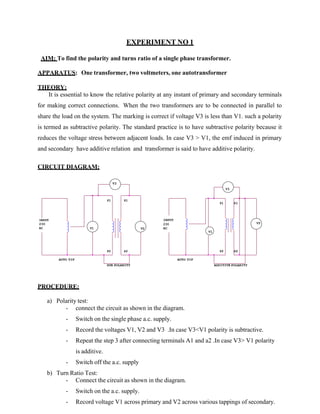
CIRCUIT DIAGRAM:
V3
V3
P1 S1
P1 S1
INPUT
230
AC V1
INPUT
230 V2
V2 AC
V1
P2 S2 P2 S2
AUTO TIF
SUB POLARITY
AUTO TIF
ADDITIVE POLARITY
PROCEDURE:
a) Polarity test:
- connect the circuit as shown in the diagram.
- Switch on the single phase a.c. supply.
- Record the voltages V1, V2 and V3 .In case V3<V1 polarity is subtractive.
- Repeat the step 3 after connecting terminals A1 and a2 .In case V3> V1 polarity
is additive.
- Switch off the a.c. supply
b) Turn Ratio Test:
- Connect the circuit as shown in the diagram.
- Switch on the a.c. supply.
- Record voltage V1 across primary and V2 across various tappings of secondary.
2. - If V1>V2 then transformer is step down.
- If V2> V1 then transformer is step up.
- Switch off a.c. supply.
OBSERVATION TABLE:
SUB-POLARITY ADD-POLARITY TURN RATIO
RESULT:
If V2>V1 then transformer is step up otherwise step down.
DISCUSSION :
The turns ratio of transformer is greater than one if it is step up
transformer and less than one if it is step down transformer.
PRECAUTIONS
1. All connections should be tight.
2. The circuit should be according to circuit diagram.
3. The power should be on when the circuit is checked completely.
QUIZ:
Q1 Whatis transformer?
A1 Transformeris a static device which is usedto changethe level of
voltageor currentwithout changingthe frequencyandpower .
Q2 What do you meanby turns ratioof transformer?
A2 Turns ratioof a transformeris theratioof primaryturnsto
the secondaryturns. Q3 Whatis transformationratioof
transformer?
A3 Transformation ratio is the ratioof secondarysideturns
to primarysideturns. Q4 What are the differentpolaritiesof
transformer?
S.NO. V1 V2 V3=V2-V1 S.NO. V1 V2 V3=V1+V2 S.NO. V1 V2 TURN RATE
V1/V2
3. A4 Positive and negative polarity.
Q5 Whatis the conditionof additivepolarity?
A5 Whenthe sumof voltagesis morethanindividualvoltages, thenit is
calledadditiveQ6 What is the conditionfor subtractivepolarity.
A6 Whenthe sumof voltagesis less thanindividualvoltages,thenit is
calledsubtractiveQ7 Whatare the differenttypes of transformer?
A7 The differenttypesof transformerare :
stepup and step down Q8 Whatis theuse
of autotransformer?
A8 Autotransformeris usedfor increasingor decreasingthevoltage with
the use of one winding Q9 Whatis theuse of polaritytest?
A9 The polaritytestis performedto find the positiveandnegative
polarityof transformer. Q10 What is the transformationratioof
step-uptransformer?
A10 It is always more than unity
4. EXPERIMENT NO 2
AIM: To perform the open circuit test on single phase transformer.
APPARATUS: One transformer, ammeter ,voltmeter ,wattmeter and autotransformer
THEORY:
• This test is performed to find the core losses.The H.V. side is open circuited.
• The rated voltage is applied on the L.V. side.
• The shunt parameters can also be find out like Loss component of no load
current,magnetizing component of no load current,Ro and Xo.
CIRCUIT DIAGRAM:
INPUT
230V
AC
M L
A
I0 C
HT
W0
LT HT
V0
OPEN
CIRCUIT
AUTO T/F
PROCEDURE:
- Connect the circuit as shown in the diagram
- Apply rated voltage on the primary side.
- Take the readings of Vo, Io and Wo.
- Calculate the shunt parameters.
- Switch off the a.c. supply
OBSERVATION TABLE:
S.NO. V0 (V0LTS) IO(AMPS) W0(Watts)
1.
5. SAMPLE CALCULATIONS:
The total iron loss= Wo
No load power factor=Wo/VoIo
Core loss component of the current= Iw= IoCosφ
Magnetising component of current= Iu=IoSinφ
Ro=V1/Iw
Xo=V1/Iu
RESULT:
The shunt parameters and core loss can be find out with open circuit test.
DISCUSSION
Open circuittest is performed to find out the core losses and shunt parametersof
transformer.
PRECAUTIONS
1 All connections should be tight.
2 The circuit should be according to circuit diagram.
3 The power should be on when the circuit is checked completely.
QUIZ:
Q1 What information do you get from open circuit test on single phase transformer?
A1 open circuit test is performed to find out the core losses and shunt parameters
Q2 Whichsideis keptopen in case of opencircuittest?
A2 Highvoltage side
Q3 Whichkind of supplyis givenon supplysideof a singlephase transformer?
A3 Full rated supply
Q4 Whatis the relationbetween magnetizingcomponent,ironloss componentandno load
currentof a singlephasetransformer?
A4 No loadcurrent=√ (Magnetisingcurrent)2+(Losscomponentof current)2
Q5 What is the power factorofa transformer underno loadcondition?
A5 0.2
Q6 Whatis the magnitude of no loadcurrentw.r.t . full loadcurrent?
A6 No loadcurrentis 5 percentof full loadcurrent.
Q7 What do you mean by equivalentcircuitof transformer?
A7 The equivalentcircuitis the representation of primaryandsecondarywinding
Resistancesandreactances alongwith losses.
Q8 Why indirecttestingof transformersis necessary?
A8 To applythe wholeload is not easyto calculatethe variousparameters.
Q9 How does the copper losses varywithvariationof loadon transformer.
A9 Copperlossesare directlyproportionalto loadon the transformer.
Q10 What do you understandby all day efficiencyof transformer?
A10 All day efficiencyis the ratioof output energy to inputenergy.
6. EXPERIMENT 3:
AIM: To perform the short circuit test on single phase transformer
APPARATUS: One transformer, ammeter , voltmeter , wattmeter and autotransformer
THEORY:
This test is carried out to find the copper losses of a transformer. In this test low voltage side is
short circuited and apparatus are connected on high voltage side.
Total copper loss=Wsc
R= Wsc/ Isc2
Z= Vsc/Isc
X= √Z2-R2
CIRCUIT DIAGRAM:
INPUT
230V
AC
VSC
L
A
ISC
HT
WSC
SHORT
CIRCUIT
AUTO T/F
PROCEDURE:
1 Connect the circuit as shown in the diagram
2 Slowly increase the supply voltage till the current is full load current.
3 Record the short circuit current and applied voltage.
4 Find the full load current.
5 Switch off the a.c. supply.
OBSERVATION TABLE:
S.NO. Vsc (V0LTS) Isc(AMPS) Wsc(Watts)
1.
LT
7. SAMPLE CALCULATIONS:
Total copper loss=Wsc
R= Wsc/ Isc2
Z= Vsc/Isc
X= √Z2-R2
RESULT:
The short circuit test is performed to find the copper losses and series parameters like the
resistance and reactance
DISCUSSION
In this test low voltage side is short circuited and apparatus are connected on high voltage side.
PRECAUTIONS
1 All connections should be tight.
2 The circuit should be according to circuit diagram.
3 The power should be on when the circuit is checked completely.
QUIZ:
Q.1 Whydo you performshort circuittest on transformer?
A1.To findthe copperlosses& seriesparametersof the transformer.
Q.2 Whichsideis shortcircuitedin short circuittest?
A2. Low voltageside
Q.3 Whichsupplyis givenin shortcircuittest?
A3 5 % to 10 % of rated voltage
Q.4 What are the differentlosses in transformer?
A4 Corelosses& copperlosses
Q.5 Whichkindof losses are foundduringshortcircuittest?
A5 Copperlosses
Q.6 What are the differenttype of transformer?
A6 Step up & stepdown
Q.7 What is the power factorof transformer?
A7 Not defined
Q.8 Namedifferent windingof transformer?
A8 Primary& secondary
Q.9 What is workingprincipleof transformer?
A9 mutualinduction
Q.10 Whatare the differentpartsof transformer?
A10 Windings core,breather,conservatortank,cooling oil,buchholzrelay.
8. EXPERIMENT NO. 4
AIM: To study the parallel operation of single phase transformers
APPARATUS: Three ammeters, three wattmeters, single phase load, two transformers,
autotransformer
THEORY:
Parallel operation of transformers is used for load sharing. The transformers are connected
in parallel on both primary and secondary side. Following conditions to be satisfied during the
parallel operation of transformers.
• Same polarities should be connected.
• The two transformers should have same voltage ratio.
• The percentage impedance should be same.
• There should be no circulating current.
CIRCUIT DIAGRAM:
INPUT
230V
AC
TF-I M L4 L
R1
uH
C 1k
W1
S/W
M
V
L
A
V IL L
O
A
D
AUTO T/F
M
A
I2 C
S/W
L
V
PROCEDURE:
TF-II
- connect the circuit as shown in the diagram.
- Note down the readings of all wattmeters , ammeters and voltmeters for given load.
- Repeat the above test for different values of load.
- Take at least three readings.
OBSERVATIOBN TABLE:
S.NO. I1 (AMPS) W1(WATTS) I2(AMPS) W2(WATTS) IL=I1+I2
(AMPS)
WL=W1+W2
(WATTS)
1.
2.
3
10
A
9. RESULT:
The two transformers connected in parallel share the load equally.
DISCUSSION:
The total load current is distributed on two transformers accordingly.
I1+I2=I l
The total wattmeter readings are distributed on two wattmeters accordingly.
W1+W2=Wl
PRECAUTIONS:
- Transformers should be connected in such a way that they have same polarity.
- All connections should be neat and tight.
- Connecting leads should be perfectly insulated.
QUIZ:
Q.1 Whatis the minimumno. of transformersneededto conductthisexp.?
A1 Two
Q.2 What is the effectof circulatingcurrentin the circuithavingtwo transformersin parallel ?
A2 produces additionalcopper losses
Q.3 when does the circulatingcurrentflowin a circuitof two transformersconnectedin parallel?
A3 If the two transformershave differentvoltageratios
Q.4 Howmuch circulatingcurrentcanbe toleratedfor paralleloperationof transformers?
A4 10%of rated value
Q.5 why the transformerare neededto be operatedin parallel.
A5 If the loadis morethan ratedload
Q.6 What willhappenif two transformersare connectedin parallel with wrongpolarity?
A6 Dead short circuiton the transformers
Q.7 What are the different polaritiesof transformer?
A7 Positiveand negative
Q8 What do you meanby impedanceof transformer?
A8 combinationof resistanceandreactance
Q9What is the workingprincipleof transformer?
A9 Mutualinduction
Q10What do you meanby loadsharing?
A10The totalloadis distributedon transformersequally.