SlideShare a Scribd company logo
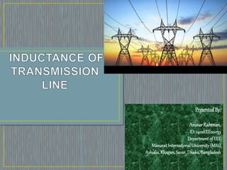
PresentedBy:
AnisurRahman,
ID: 1402EEE00033
Department of EEE
Manarat InternationalUniversity(MIU)
Ashulia,Khagan,Savar,Dhaka,Bangladesh
Definition Of Inductance
Flux Linkages of Conductors
1. Flux linkages inside the conductor
2. Flux linkages outside the conductor
 Flux linkages of one conductor in a group of
conductors
 Inductance of a single phase two wire line
 Inductance of 3-phase overhead line
 Bundled conductors
•
4
•
Consider a conductor of radius r carrying a
current I. At a distance x from the center of
this conductor, the magnetic field intensity Hx
The internal inductance per meter is
 int
int
8
H ml
I
 

  
 
7
70
int
4 10
8 8
H ml
 
 




    
If the relative permeability of the conductor is 1 (non-ferromagnetic
materials, such as copper and aluminum), the inductance per meter
reduces to
The external inductance per meter is :
The total external flux linkages per meter can be found via integration
To find the flux linkages external to a
conductor, we will consider the portion of
flux between two points P1 and P2 that lie
at distances D1 and D2 from the center of
the conductor.
Theoretically , the flux due to a conductor extends from
the center of the conductor to right unto infinity.
Assuming that the flux linkages will extend unto a point P
very far from the group of the conductors , and the
distances are as shown in fig.
Consider a group of conductors 1, 2, 3,…… n such that the
sum of currents in all these conductors is zero.
If the currents carried by respective strands are I1, I2, I3, …In
we have I1+I2+I3+…+In = 0
 ψ1p1 = All flux linkages of conductor 1 due to tis own current
I1 , internal and external , unto point P ….
Ψ1p1 = 2 × 10 I1 ln D1p/r1‘ Wb. T/Mt
Ψ1p2 = Flux linkages with conductor 1 due to current in
conductor-2
Ψ1p2 = 2 × 10 × I2 ln D2p/D12
-7
-7
Similarly ψ1p3…….ψ1pn
Ψ1p=
2 × 10 { I1 ln D1p/r'1 + I2 ln D2p/D12 +...+ In ln Dnp/D1n}
Flux linkages with conductor 1 due to I1 , I2…..In
Net flux linkages ψ1p
Ψ1p = 2 × 10 { I1 ln 1/r1'+ I2 ln 1/D12 +…+ In ln 1/D1n }
Wb-turns/m
-7
-7
The inductance of a single-phase line
consisting of two conductors of radii r
spaced by a distance D and both carrying
currents of magnitude I flowing into the
page in “A” conductor and out of the page
in the “B“ conductor.
x xH dl I Ñ
Since the path of radius x2 encloses both
conductors and the currents are equal and
opposite, the net current enclosed is 0 and,
therefore, there are no contributions to the
total inductance from the magnetic fields
at distances greater than D.
A B
The total inductance of a line per unit length in this transmission line is a sum of
the internal inductance and the external inductance between the conductor surface
(r) and the separation distance (D):
 int
1
ln
2 4
ext H m
D
l l l
r


 
     
 
By symmetry, the total inductance of the other line is the same, therefore, the total
inductance of a two-wire transmission line is
 
1
ln
4
H m
D
l
r


 
   
 
 Where r’=is GMR (Geometric mean radius)
 For a solid conductor G.M.R = 0.7788 times the radius of conductor.
 D is the distance between conductors
‘
‘
‘
In a 3-phase transmission line, the inductance of each
conductor is considered instead of loop inductance.
The conductor of a 3-phase overhead line may be placed
symmetrically or unsymmetrically on the towers.
With Symmetrical Spacing :
A 3-phase line in which the space between any two
conductor is the same as shown in fig. the line is called
symmetrical line.
Fig. shows the conductor of a 3-phase line conductor has
a radius r meters and spacing between the conductors is
D meters.
Under balanced three-phase phasor currents, the algebraic
sum of the currents in the conductors is zero.
Hence, Ia + Ib + Ic = 0
The flux linkages of the conductor ‘a’ are
ψa = 2 × 10 [ Ia ln 1/Daa + Ib ln 1/Dab + Ic ln 1/Dac ] Wb-T/m
Inductance of conductor a,
La = ψa/Ia
= 2 × 10 ln D/r‘ H/m
-7
-7
A 3-phase line in which the space between the conductors is
different as shown in fig., the line is called unsymmetrical line.
Consider 3-phase line with conductors a, b and c each of
radius r meters.
Let, the spacing between them be Dab, Dbc and Dca and the
currents flowing through them be Ia, Ib and Ic respectively as
shown in fig.
From fig, the flux linkages of the conductor a
Ψa = 2 × 10 [ Ia ln 1/r' + Ib ln 1/D12 + Ic ln 1/D31 ] Wb-T/m
-7
A bundle conductor is a conductor made up of two or
more sub-conductors and is used as one phase
conductor.
Lines of 400kv and higher voltages invariably use
bundled conductors.
Sub-conductors of a bundled conductor are separated
from each other by a constant distance varying from 0.2
m to 0.6 m depending upon designed voltage and
surrounding conditions throughout the length of the line
with the help of spacers.
It reduces corona loss.
It reduces radio interference
The bundled conductor lines transmit bulk power with
reduced losses, thereby giving increased transmission
efficiency
Bundle conductor lines have a higher capacitance to
neutral so they have higher charging current, which helps
in improving power factor
By bundling, the GMR is increased, the inductance per
phase is reduced. As a result reactance per phase is
reduced.
Inductance of transmission line

More Related Content

What's hot

Series & shunt compensation and FACTs Devices
Series & shunt compensation and FACTs DevicesSeries & shunt compensation and FACTs Devices
Series & shunt compensation and FACTs Devices
khemraj298
 
Chapter 4 mechanical design of transmission lines
Chapter 4  mechanical design of transmission linesChapter 4  mechanical design of transmission lines
Chapter 4 mechanical design of transmission lines
firaoltemesgen1
 
Chapter 3 transmission line performance
Chapter 3  transmission line performanceChapter 3  transmission line performance
Chapter 3 transmission line performance
firaoltemesgen1
 
Frequency Control of Power Systems
Frequency Control of Power SystemsFrequency Control of Power Systems
Frequency Control of Power Systems
Satya Sahoo
 
Structure of power system
Structure of power systemStructure of power system
Structure of power system
Revathi Subramaniam
 
Choice of converter configuration
Choice of converter configurationChoice of converter configuration
Choice of converter configuration
jawaharramaya
 
Distribution System Voltage Drop and Power Loss Calculation
Distribution System Voltage Drop and Power Loss CalculationDistribution System Voltage Drop and Power Loss Calculation
Distribution System Voltage Drop and Power Loss Calculation
Ameen San
 
speed control of three phase induction motor
speed control of three phase induction motorspeed control of three phase induction motor
speed control of three phase induction motor
Ashvani Shukla
 
Streamer theory
Streamer theoryStreamer theory
Streamer theory
Mohammed Almatri
 
Fault analysis using z bus
Fault analysis using z busFault analysis using z bus
Fault analysis using z bus
Revathi Subramaniam
 
UNSYMMETRICAL FAULTS IN POWER SYSTEM
UNSYMMETRICAL FAULTS IN POWER SYSTEMUNSYMMETRICAL FAULTS IN POWER SYSTEM
UNSYMMETRICAL FAULTS IN POWER SYSTEM
erramansaini1947
 
Lectures synchronous machines(1)
Lectures synchronous machines(1)Lectures synchronous machines(1)
Lectures synchronous machines(1)
Leela Marigowda
 
Three phase inverter - 180 and 120 Degree Mode of Conduction
Three phase inverter - 180 and 120 Degree Mode of ConductionThree phase inverter - 180 and 120 Degree Mode of Conduction
Three phase inverter - 180 and 120 Degree Mode of Conduction
MalarselvamV
 
FACT devices
FACT devicesFACT devices
FACT devices
Raviraj solanki
 
Generation of High D.C. Voltage (HVDC generation)
Generation of High D.C. Voltage (HVDC generation)Generation of High D.C. Voltage (HVDC generation)
Generation of High D.C. Voltage (HVDC generation)
RP6997
 
short transmission line
short transmission lineshort transmission line
short transmission line
Mohil Shah
 
Transient in Power system
Transient in Power systemTransient in Power system
Transient in Power system
Preet_patel
 
Basic types of facts controllers
Basic types of facts controllersBasic types of facts controllers
Basic types of facts controllersAyyarao T S L V
 

What's hot (20)

Series & shunt compensation and FACTs Devices
Series & shunt compensation and FACTs DevicesSeries & shunt compensation and FACTs Devices
Series & shunt compensation and FACTs Devices
 
Chapter 4 mechanical design of transmission lines
Chapter 4  mechanical design of transmission linesChapter 4  mechanical design of transmission lines
Chapter 4 mechanical design of transmission lines
 
Chapter 3 transmission line performance
Chapter 3  transmission line performanceChapter 3  transmission line performance
Chapter 3 transmission line performance
 
Frequency Control of Power Systems
Frequency Control of Power SystemsFrequency Control of Power Systems
Frequency Control of Power Systems
 
Structure of power system
Structure of power systemStructure of power system
Structure of power system
 
Choice of converter configuration
Choice of converter configurationChoice of converter configuration
Choice of converter configuration
 
Distribution System Voltage Drop and Power Loss Calculation
Distribution System Voltage Drop and Power Loss CalculationDistribution System Voltage Drop and Power Loss Calculation
Distribution System Voltage Drop and Power Loss Calculation
 
speed control of three phase induction motor
speed control of three phase induction motorspeed control of three phase induction motor
speed control of three phase induction motor
 
Streamer theory
Streamer theoryStreamer theory
Streamer theory
 
Fault analysis using z bus
Fault analysis using z busFault analysis using z bus
Fault analysis using z bus
 
UNSYMMETRICAL FAULTS IN POWER SYSTEM
UNSYMMETRICAL FAULTS IN POWER SYSTEMUNSYMMETRICAL FAULTS IN POWER SYSTEM
UNSYMMETRICAL FAULTS IN POWER SYSTEM
 
Lectures synchronous machines(1)
Lectures synchronous machines(1)Lectures synchronous machines(1)
Lectures synchronous machines(1)
 
Three phase inverter - 180 and 120 Degree Mode of Conduction
Three phase inverter - 180 and 120 Degree Mode of ConductionThree phase inverter - 180 and 120 Degree Mode of Conduction
Three phase inverter - 180 and 120 Degree Mode of Conduction
 
FACT devices
FACT devicesFACT devices
FACT devices
 
Generation of High D.C. Voltage (HVDC generation)
Generation of High D.C. Voltage (HVDC generation)Generation of High D.C. Voltage (HVDC generation)
Generation of High D.C. Voltage (HVDC generation)
 
short transmission line
short transmission lineshort transmission line
short transmission line
 
Dc fed chopper
Dc fed chopperDc fed chopper
Dc fed chopper
 
Transient in Power system
Transient in Power systemTransient in Power system
Transient in Power system
 
Basic types of facts controllers
Basic types of facts controllersBasic types of facts controllers
Basic types of facts controllers
 
Corona in power system
Corona  in power systemCorona  in power system
Corona in power system
 

Similar to Inductance of transmission line

Inductance of transmission line
Inductance of transmission lineInductance of transmission line
Inductance of transmission line
vishalgohel12195
 
Inductance of a transmission lines
Inductance of a transmission linesInductance of a transmission lines
Inductance of a transmission lines
vishalgohel12195
 
Definition of inductance, flux linkages of current carrying conductor, indu...
Definition  of inductance, flux linkages of  current carrying conductor, indu...Definition  of inductance, flux linkages of  current carrying conductor, indu...
Definition of inductance, flux linkages of current carrying conductor, indu...
vishalgohel12195
 
Lecture 5
Lecture 5Lecture 5
Lecture 5
Forward2025
 
Introduction to power system Chapter two.pdf
Introduction to power system Chapter two.pdfIntroduction to power system Chapter two.pdf
Introduction to power system Chapter two.pdf
GetahunShankoKefeni
 
Ee8402 inductance calculation
Ee8402 inductance calculationEe8402 inductance calculation
Ee8402 inductance calculation
Sugavanam KR
 
inductance in transmission lines.pptx
inductance in transmission lines.pptxinductance in transmission lines.pptx
inductance in transmission lines.pptx
NFC IET, MULTAN
 
Transmissions line power system btech notes
Transmissions line power system btech notesTransmissions line power system btech notes
Transmissions line power system btech notes
ShivamRai624135
 
INDUCTANCE & CAPACITANCE CALCULATIONS
INDUCTANCE & CAPACITANCE CALCULATIONSINDUCTANCE & CAPACITANCE CALCULATIONS
INDUCTANCE & CAPACITANCE CALCULATIONS
Duddu Rajesh
 
Chapter 3N 2021NN.pptx
Chapter 3N 2021NN.pptxChapter 3N 2021NN.pptx
Chapter 3N 2021NN.pptx
meseretyalew2014
 
Unit-3:Magnetostatics
Unit-3:MagnetostaticsUnit-3:Magnetostatics
Unit-3:Magnetostatics
Dr.SHANTHI K.G
 
Effect of earth on transmission line, bundle conductor & method of gmd
Effect of earth on transmission line, bundle conductor & method of gmdEffect of earth on transmission line, bundle conductor & method of gmd
Effect of earth on transmission line, bundle conductor & method of gmd
vishalgohel12195
 
Fisika
FisikaFisika
Fisika
Viona Vina
 
C1102021925
C1102021925C1102021925
C1102021925
IOSR Journals
 
tlwg2.ppt filters and attunatotrs notes classification of filters and attunat...
tlwg2.ppt filters and attunatotrs notes classification of filters and attunat...tlwg2.ppt filters and attunatotrs notes classification of filters and attunat...
tlwg2.ppt filters and attunatotrs notes classification of filters and attunat...
kiran93845
 
Lecture 6
Lecture 6Lecture 6
Lecture 6
Forward2025
 
Inductance and capacitance
Inductance and capacitanceInductance and capacitance
Inductance and capacitance
GHSKassKoronaMardan
 
Cp13.pptx
Cp13.pptxCp13.pptx
Cp13.pptx
DOAFCLF
 
Transmission lines and waveguides -Two marks
Transmission lines and waveguides -Two marksTransmission lines and waveguides -Two marks
Transmission lines and waveguides -Two marks
Dr.SHANTHI K.G
 
EC8651 Transmissions lines and RF systems-two marks
EC8651  Transmissions lines and RF systems-two marksEC8651  Transmissions lines and RF systems-two marks
EC8651 Transmissions lines and RF systems-two marks
Dr.SHANTHI K.G
 

Similar to Inductance of transmission line (20)

Inductance of transmission line
Inductance of transmission lineInductance of transmission line
Inductance of transmission line
 
Inductance of a transmission lines
Inductance of a transmission linesInductance of a transmission lines
Inductance of a transmission lines
 
Definition of inductance, flux linkages of current carrying conductor, indu...
Definition  of inductance, flux linkages of  current carrying conductor, indu...Definition  of inductance, flux linkages of  current carrying conductor, indu...
Definition of inductance, flux linkages of current carrying conductor, indu...
 
Lecture 5
Lecture 5Lecture 5
Lecture 5
 
Introduction to power system Chapter two.pdf
Introduction to power system Chapter two.pdfIntroduction to power system Chapter two.pdf
Introduction to power system Chapter two.pdf
 
Ee8402 inductance calculation
Ee8402 inductance calculationEe8402 inductance calculation
Ee8402 inductance calculation
 
inductance in transmission lines.pptx
inductance in transmission lines.pptxinductance in transmission lines.pptx
inductance in transmission lines.pptx
 
Transmissions line power system btech notes
Transmissions line power system btech notesTransmissions line power system btech notes
Transmissions line power system btech notes
 
INDUCTANCE & CAPACITANCE CALCULATIONS
INDUCTANCE & CAPACITANCE CALCULATIONSINDUCTANCE & CAPACITANCE CALCULATIONS
INDUCTANCE & CAPACITANCE CALCULATIONS
 
Chapter 3N 2021NN.pptx
Chapter 3N 2021NN.pptxChapter 3N 2021NN.pptx
Chapter 3N 2021NN.pptx
 
Unit-3:Magnetostatics
Unit-3:MagnetostaticsUnit-3:Magnetostatics
Unit-3:Magnetostatics
 
Effect of earth on transmission line, bundle conductor & method of gmd
Effect of earth on transmission line, bundle conductor & method of gmdEffect of earth on transmission line, bundle conductor & method of gmd
Effect of earth on transmission line, bundle conductor & method of gmd
 
Fisika
FisikaFisika
Fisika
 
C1102021925
C1102021925C1102021925
C1102021925
 
tlwg2.ppt filters and attunatotrs notes classification of filters and attunat...
tlwg2.ppt filters and attunatotrs notes classification of filters and attunat...tlwg2.ppt filters and attunatotrs notes classification of filters and attunat...
tlwg2.ppt filters and attunatotrs notes classification of filters and attunat...
 
Lecture 6
Lecture 6Lecture 6
Lecture 6
 
Inductance and capacitance
Inductance and capacitanceInductance and capacitance
Inductance and capacitance
 
Cp13.pptx
Cp13.pptxCp13.pptx
Cp13.pptx
 
Transmission lines and waveguides -Two marks
Transmission lines and waveguides -Two marksTransmission lines and waveguides -Two marks
Transmission lines and waveguides -Two marks
 
EC8651 Transmissions lines and RF systems-two marks
EC8651  Transmissions lines and RF systems-two marksEC8651  Transmissions lines and RF systems-two marks
EC8651 Transmissions lines and RF systems-two marks
 

More from Anisur Rahman

Underground cables
Underground cablesUnderground cables
Underground cables
Anisur Rahman
 
Control systems engineering
Control systems engineeringControl systems engineering
Control systems engineering
Anisur Rahman
 
Construction and working principle of optical fiber
Construction and working principle of optical fiberConstruction and working principle of optical fiber
Construction and working principle of optical fiber
Anisur Rahman
 
2016 Fall result 3.9
2016 Fall result 3.9 2016 Fall result 3.9
2016 Fall result 3.9 Anisur Rahman
 
Wifi technology
Wifi technologyWifi technology
Wifi technology
Anisur Rahman
 
Transistor biasing
Transistor biasing Transistor biasing
Transistor biasing
Anisur Rahman
 
Essential computing
Essential computingEssential computing
Essential computing
Anisur Rahman
 
Emitter bias method of transistor biasing
Emitter bias method of transistor biasingEmitter bias method of transistor biasing
Emitter bias method of transistor biasing
Anisur Rahman
 
Autobiography
AutobiographyAutobiography
Autobiography
Anisur Rahman
 
Autobiography
AutobiographyAutobiography
Autobiography
Anisur Rahman
 
Autobiography
AutobiographyAutobiography
Autobiography
Anisur Rahman
 
Generations of wireless communication technologies and upcoming world
Generations of wireless communication technologies and upcoming worldGenerations of wireless communication technologies and upcoming world
Generations of wireless communication technologies and upcoming world
Anisur Rahman
 

More from Anisur Rahman (12)

Underground cables
Underground cablesUnderground cables
Underground cables
 
Control systems engineering
Control systems engineeringControl systems engineering
Control systems engineering
 
Construction and working principle of optical fiber
Construction and working principle of optical fiberConstruction and working principle of optical fiber
Construction and working principle of optical fiber
 
2016 Fall result 3.9
2016 Fall result 3.9 2016 Fall result 3.9
2016 Fall result 3.9
 
Wifi technology
Wifi technologyWifi technology
Wifi technology
 
Transistor biasing
Transistor biasing Transistor biasing
Transistor biasing
 
Essential computing
Essential computingEssential computing
Essential computing
 
Emitter bias method of transistor biasing
Emitter bias method of transistor biasingEmitter bias method of transistor biasing
Emitter bias method of transistor biasing
 
Autobiography
AutobiographyAutobiography
Autobiography
 
Autobiography
AutobiographyAutobiography
Autobiography
 
Autobiography
AutobiographyAutobiography
Autobiography
 
Generations of wireless communication technologies and upcoming world
Generations of wireless communication technologies and upcoming worldGenerations of wireless communication technologies and upcoming world
Generations of wireless communication technologies and upcoming world
 

Recently uploaded

Sachpazis:Terzaghi Bearing Capacity Estimation in simple terms with Calculati...
Sachpazis:Terzaghi Bearing Capacity Estimation in simple terms with Calculati...Sachpazis:Terzaghi Bearing Capacity Estimation in simple terms with Calculati...
Sachpazis:Terzaghi Bearing Capacity Estimation in simple terms with Calculati...
Dr.Costas Sachpazis
 
Water Industry Process Automation and Control Monthly - May 2024.pdf
Water Industry Process Automation and Control Monthly - May 2024.pdfWater Industry Process Automation and Control Monthly - May 2024.pdf
Water Industry Process Automation and Control Monthly - May 2024.pdf
Water Industry Process Automation & Control
 
Governing Equations for Fundamental Aerodynamics_Anderson2010.pdf
Governing Equations for Fundamental Aerodynamics_Anderson2010.pdfGoverning Equations for Fundamental Aerodynamics_Anderson2010.pdf
Governing Equations for Fundamental Aerodynamics_Anderson2010.pdf
WENKENLI1
 
AP LAB PPT.pdf ap lab ppt no title specific
AP LAB PPT.pdf ap lab ppt no title specificAP LAB PPT.pdf ap lab ppt no title specific
AP LAB PPT.pdf ap lab ppt no title specific
BrazilAccount1
 
Investor-Presentation-Q1FY2024 investor presentation document.pptx
Investor-Presentation-Q1FY2024 investor presentation document.pptxInvestor-Presentation-Q1FY2024 investor presentation document.pptx
Investor-Presentation-Q1FY2024 investor presentation document.pptx
AmarGB2
 
power quality voltage fluctuation UNIT - I.pptx
power quality voltage fluctuation UNIT - I.pptxpower quality voltage fluctuation UNIT - I.pptx
power quality voltage fluctuation UNIT - I.pptx
ViniHema
 
DESIGN A COTTON SEED SEPARATION MACHINE.docx
DESIGN A COTTON SEED SEPARATION MACHINE.docxDESIGN A COTTON SEED SEPARATION MACHINE.docx
DESIGN A COTTON SEED SEPARATION MACHINE.docx
FluxPrime1
 
block diagram and signal flow graph representation
block diagram and signal flow graph representationblock diagram and signal flow graph representation
block diagram and signal flow graph representation
Divya Somashekar
 
The Benefits and Techniques of Trenchless Pipe Repair.pdf
The Benefits and Techniques of Trenchless Pipe Repair.pdfThe Benefits and Techniques of Trenchless Pipe Repair.pdf
The Benefits and Techniques of Trenchless Pipe Repair.pdf
Pipe Restoration Solutions
 
The role of big data in decision making.
The role of big data in decision making.The role of big data in decision making.
The role of big data in decision making.
ankuprajapati0525
 
Immunizing Image Classifiers Against Localized Adversary Attacks
Immunizing Image Classifiers Against Localized Adversary AttacksImmunizing Image Classifiers Against Localized Adversary Attacks
Immunizing Image Classifiers Against Localized Adversary Attacks
gerogepatton
 
Hierarchical Digital Twin of a Naval Power System
Hierarchical Digital Twin of a Naval Power SystemHierarchical Digital Twin of a Naval Power System
Hierarchical Digital Twin of a Naval Power System
Kerry Sado
 
HYDROPOWER - Hydroelectric power generation
HYDROPOWER - Hydroelectric power generationHYDROPOWER - Hydroelectric power generation
HYDROPOWER - Hydroelectric power generation
Robbie Edward Sayers
 
Top 10 Oil and Gas Projects in Saudi Arabia 2024.pdf
Top 10 Oil and Gas Projects in Saudi Arabia 2024.pdfTop 10 Oil and Gas Projects in Saudi Arabia 2024.pdf
Top 10 Oil and Gas Projects in Saudi Arabia 2024.pdf
Teleport Manpower Consultant
 
Railway Signalling Principles Edition 3.pdf
Railway Signalling Principles Edition 3.pdfRailway Signalling Principles Edition 3.pdf
Railway Signalling Principles Edition 3.pdf
TeeVichai
 
Architectural Portfolio Sean Lockwood
Architectural Portfolio Sean LockwoodArchitectural Portfolio Sean Lockwood
Architectural Portfolio Sean Lockwood
seandesed
 
H.Seo, ICLR 2024, MLILAB, KAIST AI.pdf
H.Seo,  ICLR 2024, MLILAB,  KAIST AI.pdfH.Seo,  ICLR 2024, MLILAB,  KAIST AI.pdf
H.Seo, ICLR 2024, MLILAB, KAIST AI.pdf
MLILAB
 
Gen AI Study Jams _ For the GDSC Leads in India.pdf
Gen AI Study Jams _ For the GDSC Leads in India.pdfGen AI Study Jams _ For the GDSC Leads in India.pdf
Gen AI Study Jams _ For the GDSC Leads in India.pdf
gdsczhcet
 
NO1 Uk best vashikaran specialist in delhi vashikaran baba near me online vas...
NO1 Uk best vashikaran specialist in delhi vashikaran baba near me online vas...NO1 Uk best vashikaran specialist in delhi vashikaran baba near me online vas...
NO1 Uk best vashikaran specialist in delhi vashikaran baba near me online vas...
Amil Baba Dawood bangali
 
space technology lecture notes on satellite
space technology lecture notes on satellitespace technology lecture notes on satellite
space technology lecture notes on satellite
ongomchris
 

Recently uploaded (20)

Sachpazis:Terzaghi Bearing Capacity Estimation in simple terms with Calculati...
Sachpazis:Terzaghi Bearing Capacity Estimation in simple terms with Calculati...Sachpazis:Terzaghi Bearing Capacity Estimation in simple terms with Calculati...
Sachpazis:Terzaghi Bearing Capacity Estimation in simple terms with Calculati...
 
Water Industry Process Automation and Control Monthly - May 2024.pdf
Water Industry Process Automation and Control Monthly - May 2024.pdfWater Industry Process Automation and Control Monthly - May 2024.pdf
Water Industry Process Automation and Control Monthly - May 2024.pdf
 
Governing Equations for Fundamental Aerodynamics_Anderson2010.pdf
Governing Equations for Fundamental Aerodynamics_Anderson2010.pdfGoverning Equations for Fundamental Aerodynamics_Anderson2010.pdf
Governing Equations for Fundamental Aerodynamics_Anderson2010.pdf
 
AP LAB PPT.pdf ap lab ppt no title specific
AP LAB PPT.pdf ap lab ppt no title specificAP LAB PPT.pdf ap lab ppt no title specific
AP LAB PPT.pdf ap lab ppt no title specific
 
Investor-Presentation-Q1FY2024 investor presentation document.pptx
Investor-Presentation-Q1FY2024 investor presentation document.pptxInvestor-Presentation-Q1FY2024 investor presentation document.pptx
Investor-Presentation-Q1FY2024 investor presentation document.pptx
 
power quality voltage fluctuation UNIT - I.pptx
power quality voltage fluctuation UNIT - I.pptxpower quality voltage fluctuation UNIT - I.pptx
power quality voltage fluctuation UNIT - I.pptx
 
DESIGN A COTTON SEED SEPARATION MACHINE.docx
DESIGN A COTTON SEED SEPARATION MACHINE.docxDESIGN A COTTON SEED SEPARATION MACHINE.docx
DESIGN A COTTON SEED SEPARATION MACHINE.docx
 
block diagram and signal flow graph representation
block diagram and signal flow graph representationblock diagram and signal flow graph representation
block diagram and signal flow graph representation
 
The Benefits and Techniques of Trenchless Pipe Repair.pdf
The Benefits and Techniques of Trenchless Pipe Repair.pdfThe Benefits and Techniques of Trenchless Pipe Repair.pdf
The Benefits and Techniques of Trenchless Pipe Repair.pdf
 
The role of big data in decision making.
The role of big data in decision making.The role of big data in decision making.
The role of big data in decision making.
 
Immunizing Image Classifiers Against Localized Adversary Attacks
Immunizing Image Classifiers Against Localized Adversary AttacksImmunizing Image Classifiers Against Localized Adversary Attacks
Immunizing Image Classifiers Against Localized Adversary Attacks
 
Hierarchical Digital Twin of a Naval Power System
Hierarchical Digital Twin of a Naval Power SystemHierarchical Digital Twin of a Naval Power System
Hierarchical Digital Twin of a Naval Power System
 
HYDROPOWER - Hydroelectric power generation
HYDROPOWER - Hydroelectric power generationHYDROPOWER - Hydroelectric power generation
HYDROPOWER - Hydroelectric power generation
 
Top 10 Oil and Gas Projects in Saudi Arabia 2024.pdf
Top 10 Oil and Gas Projects in Saudi Arabia 2024.pdfTop 10 Oil and Gas Projects in Saudi Arabia 2024.pdf
Top 10 Oil and Gas Projects in Saudi Arabia 2024.pdf
 
Railway Signalling Principles Edition 3.pdf
Railway Signalling Principles Edition 3.pdfRailway Signalling Principles Edition 3.pdf
Railway Signalling Principles Edition 3.pdf
 
Architectural Portfolio Sean Lockwood
Architectural Portfolio Sean LockwoodArchitectural Portfolio Sean Lockwood
Architectural Portfolio Sean Lockwood
 
H.Seo, ICLR 2024, MLILAB, KAIST AI.pdf
H.Seo,  ICLR 2024, MLILAB,  KAIST AI.pdfH.Seo,  ICLR 2024, MLILAB,  KAIST AI.pdf
H.Seo, ICLR 2024, MLILAB, KAIST AI.pdf
 
Gen AI Study Jams _ For the GDSC Leads in India.pdf
Gen AI Study Jams _ For the GDSC Leads in India.pdfGen AI Study Jams _ For the GDSC Leads in India.pdf
Gen AI Study Jams _ For the GDSC Leads in India.pdf
 
NO1 Uk best vashikaran specialist in delhi vashikaran baba near me online vas...
NO1 Uk best vashikaran specialist in delhi vashikaran baba near me online vas...NO1 Uk best vashikaran specialist in delhi vashikaran baba near me online vas...
NO1 Uk best vashikaran specialist in delhi vashikaran baba near me online vas...
 
space technology lecture notes on satellite
space technology lecture notes on satellitespace technology lecture notes on satellite
space technology lecture notes on satellite
 

Inductance of transmission line

  • 1. PresentedBy: AnisurRahman, ID: 1402EEE00033 Department of EEE Manarat InternationalUniversity(MIU) Ashulia,Khagan,Savar,Dhaka,Bangladesh
  • 2. Definition Of Inductance Flux Linkages of Conductors 1. Flux linkages inside the conductor 2. Flux linkages outside the conductor  Flux linkages of one conductor in a group of conductors  Inductance of a single phase two wire line  Inductance of 3-phase overhead line  Bundled conductors
  • 3.
  • 5. Consider a conductor of radius r carrying a current I. At a distance x from the center of this conductor, the magnetic field intensity Hx The internal inductance per meter is  int int 8 H ml I         7 70 int 4 10 8 8 H ml              If the relative permeability of the conductor is 1 (non-ferromagnetic materials, such as copper and aluminum), the inductance per meter reduces to
  • 6. The external inductance per meter is : The total external flux linkages per meter can be found via integration To find the flux linkages external to a conductor, we will consider the portion of flux between two points P1 and P2 that lie at distances D1 and D2 from the center of the conductor.
  • 7. Theoretically , the flux due to a conductor extends from the center of the conductor to right unto infinity. Assuming that the flux linkages will extend unto a point P very far from the group of the conductors , and the distances are as shown in fig.
  • 8. Consider a group of conductors 1, 2, 3,…… n such that the sum of currents in all these conductors is zero. If the currents carried by respective strands are I1, I2, I3, …In we have I1+I2+I3+…+In = 0  ψ1p1 = All flux linkages of conductor 1 due to tis own current I1 , internal and external , unto point P …. Ψ1p1 = 2 × 10 I1 ln D1p/r1‘ Wb. T/Mt Ψ1p2 = Flux linkages with conductor 1 due to current in conductor-2 Ψ1p2 = 2 × 10 × I2 ln D2p/D12 -7 -7
  • 9. Similarly ψ1p3…….ψ1pn Ψ1p= 2 × 10 { I1 ln D1p/r'1 + I2 ln D2p/D12 +...+ In ln Dnp/D1n} Flux linkages with conductor 1 due to I1 , I2…..In Net flux linkages ψ1p Ψ1p = 2 × 10 { I1 ln 1/r1'+ I2 ln 1/D12 +…+ In ln 1/D1n } Wb-turns/m -7 -7
  • 10. The inductance of a single-phase line consisting of two conductors of radii r spaced by a distance D and both carrying currents of magnitude I flowing into the page in “A” conductor and out of the page in the “B“ conductor. x xH dl I Ñ Since the path of radius x2 encloses both conductors and the currents are equal and opposite, the net current enclosed is 0 and, therefore, there are no contributions to the total inductance from the magnetic fields at distances greater than D. A B
  • 11. The total inductance of a line per unit length in this transmission line is a sum of the internal inductance and the external inductance between the conductor surface (r) and the separation distance (D):  int 1 ln 2 4 ext H m D l l l r             By symmetry, the total inductance of the other line is the same, therefore, the total inductance of a two-wire transmission line is   1 ln 4 H m D l r            Where r’=is GMR (Geometric mean radius)  For a solid conductor G.M.R = 0.7788 times the radius of conductor.  D is the distance between conductors ‘ ‘ ‘
  • 12. In a 3-phase transmission line, the inductance of each conductor is considered instead of loop inductance. The conductor of a 3-phase overhead line may be placed symmetrically or unsymmetrically on the towers. With Symmetrical Spacing : A 3-phase line in which the space between any two conductor is the same as shown in fig. the line is called symmetrical line. Fig. shows the conductor of a 3-phase line conductor has a radius r meters and spacing between the conductors is D meters.
  • 13. Under balanced three-phase phasor currents, the algebraic sum of the currents in the conductors is zero. Hence, Ia + Ib + Ic = 0 The flux linkages of the conductor ‘a’ are ψa = 2 × 10 [ Ia ln 1/Daa + Ib ln 1/Dab + Ic ln 1/Dac ] Wb-T/m Inductance of conductor a, La = ψa/Ia = 2 × 10 ln D/r‘ H/m -7 -7
  • 14. A 3-phase line in which the space between the conductors is different as shown in fig., the line is called unsymmetrical line. Consider 3-phase line with conductors a, b and c each of radius r meters.
  • 15. Let, the spacing between them be Dab, Dbc and Dca and the currents flowing through them be Ia, Ib and Ic respectively as shown in fig. From fig, the flux linkages of the conductor a Ψa = 2 × 10 [ Ia ln 1/r' + Ib ln 1/D12 + Ic ln 1/D31 ] Wb-T/m -7
  • 16. A bundle conductor is a conductor made up of two or more sub-conductors and is used as one phase conductor. Lines of 400kv and higher voltages invariably use bundled conductors. Sub-conductors of a bundled conductor are separated from each other by a constant distance varying from 0.2 m to 0.6 m depending upon designed voltage and surrounding conditions throughout the length of the line with the help of spacers.
  • 17. It reduces corona loss. It reduces radio interference The bundled conductor lines transmit bulk power with reduced losses, thereby giving increased transmission efficiency Bundle conductor lines have a higher capacitance to neutral so they have higher charging current, which helps in improving power factor By bundling, the GMR is increased, the inductance per phase is reduced. As a result reactance per phase is reduced.