Downloaded 1,084 times
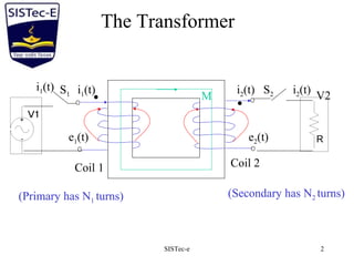
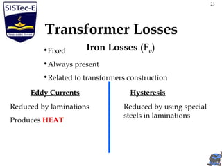
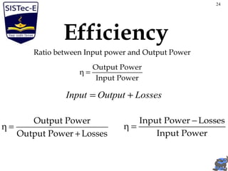
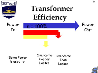
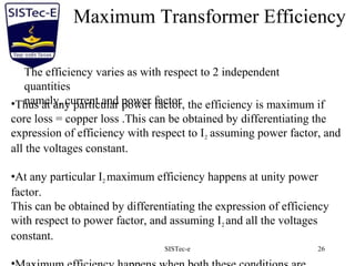
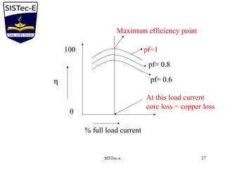
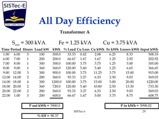


The document provides a comprehensive overview of single-phase transformers, including their construction, operation, and equivalent circuits. It discusses the concept of transformer losses, such as copper, eddy current, and hysteresis losses, as well as methods for testing and determining transformer efficiency. Additionally, it covers transformer regulation and how to ensure optimal performance under varying load conditions.