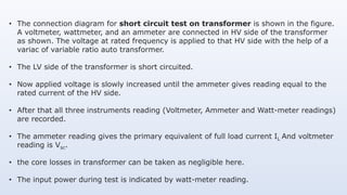
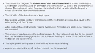
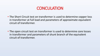
The document outlines the short-circuit and open-circuit tests on transformers to understand their working principles and determine equivalent circuit parameters. The short-circuit test helps in evaluating copper losses at full load, while the open-circuit test assesses core losses and parameters of the shunt branch. Detailed procedures for conducting both tests, along with example computations for a specific transformer, are provided.
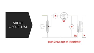
![• Computation with S.C test data
Calculation of series parameters is rather simple and as follows.
Power drawn Wsc = sq(Isc) re2 or, re2 = Wsc/ sq(Isc) = 2 175 12.5 ∴ re2 = 1.12Ω Now S.C
impedance zsc = Vsc/ Isc = 20/12.5 ∴ zsc = 1.6Ω= sq root[sq(re2) + sq(xe2)] Thus, xe2 =
1.14Ω .
Although calculation of parameters from the test results are over, it is very important to
note that parallel branch parameters have been obtained referred to LV side and series
branch parameters have been obtained referred to HV side.](https://image.slidesharecdn.com/short-circuitandopen-circuittestontransformer-171027124355/85/Open-circuit-and-Short-circuit-test-on-transformer-17-320.jpg)


