Downloaded 1,563 times
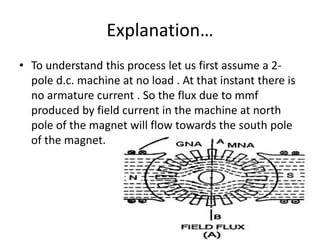
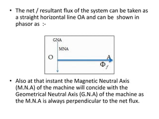
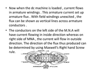
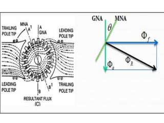


Armature reaction in a DC machine is the effect of armature flux on the main field flux. It has two undesirable effects - it demagnetizes the main flux and distorts the main flux. This reduces generated voltage and torque and influences commutation limits. Methods to reduce armature reaction include compensating windings and interpoles, which produce fields opposing the armature flux effects.


![Amit seth armature_reaction[1]](https://cdn.slidesharecdn.com/ss_thumbnails/amitsetharmaturereaction1-151213065631-thumbnail.jpg?width=640&height=640&fit=bounds)