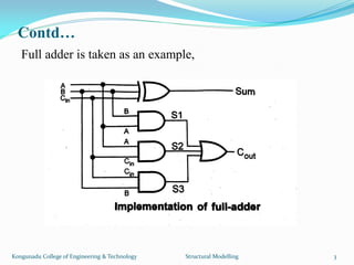
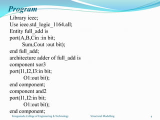
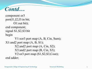
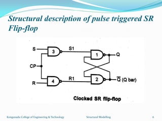
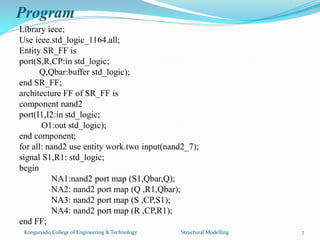
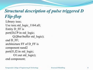
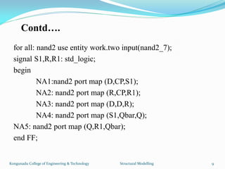
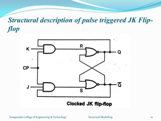
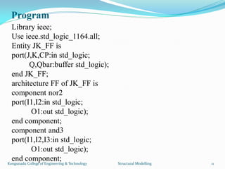
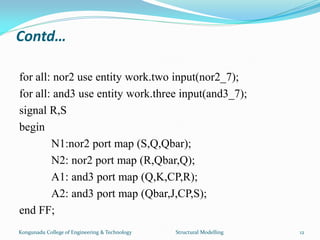
Contents:
 Introduction
 VHDL structural Modelling Programs –Full Adder, SR Flip
flop, JK Flip flop & D flip flops
Kongunadu College of Engineering & Technology Structural Modelling 1
Structural Modelling
 In structural design, a VHDL and a Verilog uses components or
gates to model the system.
 The important features of VHDL structural type of architecture
body are:
 Design hierarchy
 Components are used
 Each component is simulated separately.
 In the structural modeling, an entity is described as a set of
components connected by signals, that is, as a net list.
 The architecture body is composed of two parts: the declarative
part and the statement parts.
Kongunadu College of Engineering & Technology Structural Modelling 2
Contd…
Full adder is taken as an example,
Kongunadu College of Engineering & Technology Structural Modelling 3
Program
Library ieee;
Use ieee.std_logic_1164.all;
Entity full_add is
port(A,B,Cin :in bit;
Sum,Cout :out bit);
end full_add;
architecture adder of full_add is
component xor3
port(I1,I2,I3:in bit;
O1:out bit);
end component;
component and2
port(I1,I2:in bit;
O1:out bit);
end component;
Kongunadu College of Engineering & Technology Structural Modelling 4
Contd…
component or3
port(I1,I2,I3:in bit;
O1:out bit);
end component;
signal S1,S2,S3:bit
begin
Y1:xor3 port map (A, B, Cin, Sum);
X1:and2 port map (A, B, S1);
X2:and2 port map (A, Cin, S2);
X3:and2 port map (B, Cin, S3);
Y2:or3 port map (S1,S2,S3,Cout);
end adder;
Kongunadu College of Engineering & Technology Structural Modelling 5
Structural description of pulse triggered SR
Flip-flop
Kongunadu College of Engineering & Technology Structural Modelling 6
Program
Library ieee;
Use ieee.std_logic_1164.all;
Entity SR_FF is
port(S,R,CP:in std_logic;
Q,Qbar:buffer std_logic);
end SR_FF;
architecture FF of SR_FF is
component nand2
port(I1,I2:in std_logic;
O1:out std_logic);
end component;
for all: nand2 use entity work.two input(nand2_7);
signal S1,R1: std_logic;
begin
NA1:nand2 port map (S1,Qbar,Q);
NA2: nand2 port map (Q ,R1,Qbar);
NA3: nand2 port map (S ,CP,S1);
NA4: nand2 port map (R ,CP,R1);
end FF;
Kongunadu College of Engineering & Technology Structural Modelling 7
Structural description of pulse triggered D
Flip-flop
Library ieee;
Use ieee.std_logic_1164.all;
Entity D_FF is
port(D,CP:in std_logic;
Q,Qbar:buffer std_logic);
end D_FF;
architecture FF of D_FF is
component nand2
port(I1,I2:in std_logic;
O1:out std_logic);
end component;
Kongunadu College of Engineering & Technology Structural Modelling 8
for all: nand2 use entity work.two input(nand2_7);
signal S1,R,R1: std_logic;
begin
NA1:nand2 port map (D,CP,S1);
NA2: nand2 port map (R,CP,R1);
NA3: nand2 port map (D,D,R);
NA4: nand2 port map (S1,Qbar,Q);
NA5: nand2 port map (Q,R1,Qbar);
end FF;
Contd….
Kongunadu College of Engineering & Technology Structural Modelling 9
Structural description of pulse triggered JK Flip-
flop
Kongunadu College of Engineering & Technology Structural Modelling 10
Program
Library ieee;
Use ieee.std_logic_1164.all;
Entity JK_FF is
port(J,K,CP:in std_logic;
Q,Qbar:buffer std_logic);
end JK_FF;
architecture FF of JK_FF is
component nor2
port(I1,I2:in std_logic;
O1:out std_logic);
end component;
component and3
port(I1,I2,I3:in std_logic;
O1:out std_logic);
end component;Kongunadu College of Engineering & Technology Structural Modelling 11
Contd…
for all: nor2 use entity work.two input(nor2_7);
for all: and3 use entity work.three input(and3_7);
signal R,S
begin
N1:nor2 port map (S,Q,Qbar);
N2: nor2 port map (R,Qbar,Q);
A1: and3 port map (Q,K,CP,R);
A2: and3 port map (Qbar,J,CP,S);
end FF;
Kongunadu College of Engineering & Technology Structural Modelling 12
Conclusion:
The basics of structural modelling is explained in detail with examples.
References:
1. Mandal, “Digital Electronics Principles & Application, McGraw Hill Edu, 2013.
2. William Keitz, Digital Electronics-A Practical Approach with VHDL, Pearson, 2013.
3. Thomas L.Floyd, ‘Digital Fundamentals’, 11th edition, Pearson Education, 2015.
4. Charles H.Roth, Jr, Lizy Lizy Kurian John, ‘Digital System Design using VHDL,
Cengage,2013.
5. D.P.Kothari,J.S.Dhillon, ‘Digital circuits and Design’,Pearson Education, 2016.
6. A.P.Godse., Dr.D.A.Godse, ‘Digital Logic Circuits’ , Technical Publications Third Edition
2016
7. Other Web Sources
Kongunadu College of Engineering & Technology Structural Modelling 13

Structural modelling

  • 1.
    Contents:  Introduction  VHDLstructural Modelling Programs –Full Adder, SR Flip flop, JK Flip flop & D flip flops Kongunadu College of Engineering & Technology Structural Modelling 1
  • 2.
    Structural Modelling  Instructural design, a VHDL and a Verilog uses components or gates to model the system.  The important features of VHDL structural type of architecture body are:  Design hierarchy  Components are used  Each component is simulated separately.  In the structural modeling, an entity is described as a set of components connected by signals, that is, as a net list.  The architecture body is composed of two parts: the declarative part and the statement parts. Kongunadu College of Engineering & Technology Structural Modelling 2
  • 3.
    Contd… Full adder istaken as an example, Kongunadu College of Engineering & Technology Structural Modelling 3
  • 4.
    Program Library ieee; Use ieee.std_logic_1164.all; Entityfull_add is port(A,B,Cin :in bit; Sum,Cout :out bit); end full_add; architecture adder of full_add is component xor3 port(I1,I2,I3:in bit; O1:out bit); end component; component and2 port(I1,I2:in bit; O1:out bit); end component; Kongunadu College of Engineering & Technology Structural Modelling 4
  • 5.
    Contd… component or3 port(I1,I2,I3:in bit; O1:outbit); end component; signal S1,S2,S3:bit begin Y1:xor3 port map (A, B, Cin, Sum); X1:and2 port map (A, B, S1); X2:and2 port map (A, Cin, S2); X3:and2 port map (B, Cin, S3); Y2:or3 port map (S1,S2,S3,Cout); end adder; Kongunadu College of Engineering & Technology Structural Modelling 5
  • 6.
    Structural description ofpulse triggered SR Flip-flop Kongunadu College of Engineering & Technology Structural Modelling 6
  • 7.
    Program Library ieee; Use ieee.std_logic_1164.all; EntitySR_FF is port(S,R,CP:in std_logic; Q,Qbar:buffer std_logic); end SR_FF; architecture FF of SR_FF is component nand2 port(I1,I2:in std_logic; O1:out std_logic); end component; for all: nand2 use entity work.two input(nand2_7); signal S1,R1: std_logic; begin NA1:nand2 port map (S1,Qbar,Q); NA2: nand2 port map (Q ,R1,Qbar); NA3: nand2 port map (S ,CP,S1); NA4: nand2 port map (R ,CP,R1); end FF; Kongunadu College of Engineering & Technology Structural Modelling 7
  • 8.
    Structural description ofpulse triggered D Flip-flop Library ieee; Use ieee.std_logic_1164.all; Entity D_FF is port(D,CP:in std_logic; Q,Qbar:buffer std_logic); end D_FF; architecture FF of D_FF is component nand2 port(I1,I2:in std_logic; O1:out std_logic); end component; Kongunadu College of Engineering & Technology Structural Modelling 8
  • 9.
    for all: nand2use entity work.two input(nand2_7); signal S1,R,R1: std_logic; begin NA1:nand2 port map (D,CP,S1); NA2: nand2 port map (R,CP,R1); NA3: nand2 port map (D,D,R); NA4: nand2 port map (S1,Qbar,Q); NA5: nand2 port map (Q,R1,Qbar); end FF; Contd…. Kongunadu College of Engineering & Technology Structural Modelling 9
  • 10.
    Structural description ofpulse triggered JK Flip- flop Kongunadu College of Engineering & Technology Structural Modelling 10
  • 11.
    Program Library ieee; Use ieee.std_logic_1164.all; EntityJK_FF is port(J,K,CP:in std_logic; Q,Qbar:buffer std_logic); end JK_FF; architecture FF of JK_FF is component nor2 port(I1,I2:in std_logic; O1:out std_logic); end component; component and3 port(I1,I2,I3:in std_logic; O1:out std_logic); end component;Kongunadu College of Engineering & Technology Structural Modelling 11
  • 12.
    Contd… for all: nor2use entity work.two input(nor2_7); for all: and3 use entity work.three input(and3_7); signal R,S begin N1:nor2 port map (S,Q,Qbar); N2: nor2 port map (R,Qbar,Q); A1: and3 port map (Q,K,CP,R); A2: and3 port map (Qbar,J,CP,S); end FF; Kongunadu College of Engineering & Technology Structural Modelling 12
  • 13.
    Conclusion: The basics ofstructural modelling is explained in detail with examples. References: 1. Mandal, “Digital Electronics Principles & Application, McGraw Hill Edu, 2013. 2. William Keitz, Digital Electronics-A Practical Approach with VHDL, Pearson, 2013. 3. Thomas L.Floyd, ‘Digital Fundamentals’, 11th edition, Pearson Education, 2015. 4. Charles H.Roth, Jr, Lizy Lizy Kurian John, ‘Digital System Design using VHDL, Cengage,2013. 5. D.P.Kothari,J.S.Dhillon, ‘Digital circuits and Design’,Pearson Education, 2016. 6. A.P.Godse., Dr.D.A.Godse, ‘Digital Logic Circuits’ , Technical Publications Third Edition 2016 7. Other Web Sources Kongunadu College of Engineering & Technology Structural Modelling 13