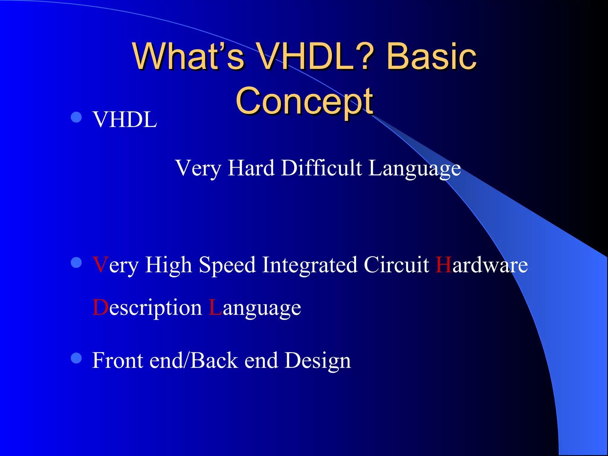
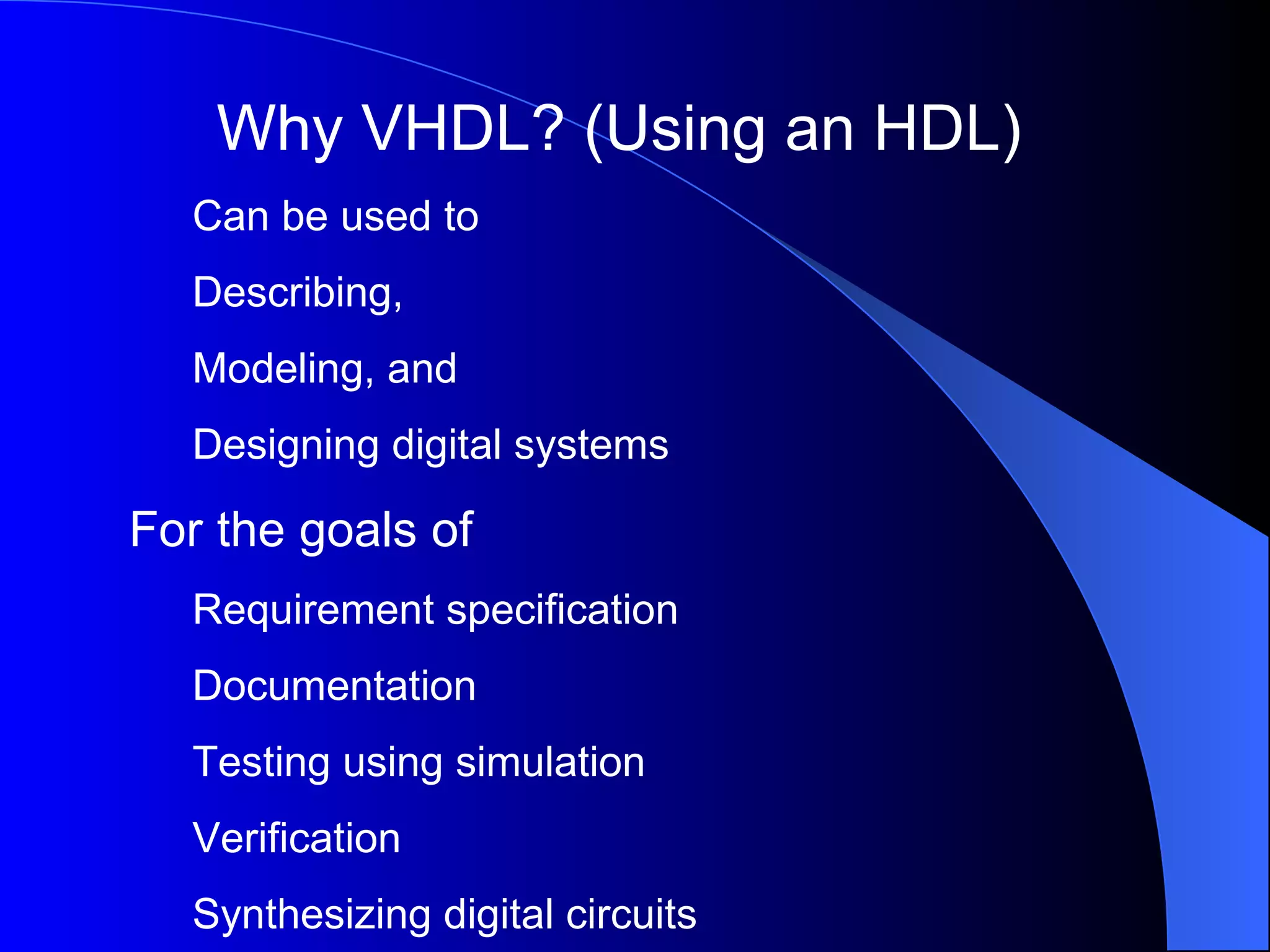
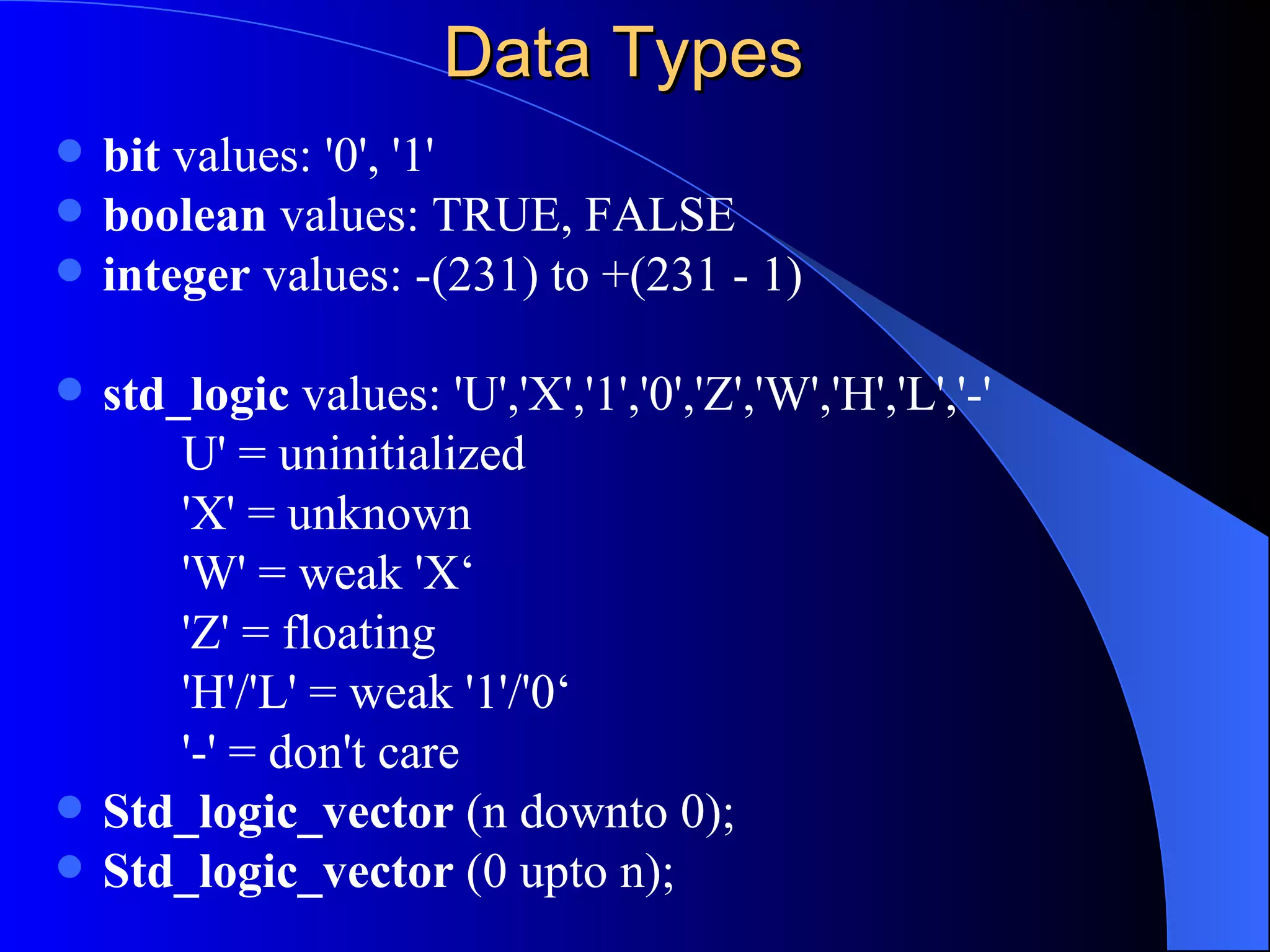
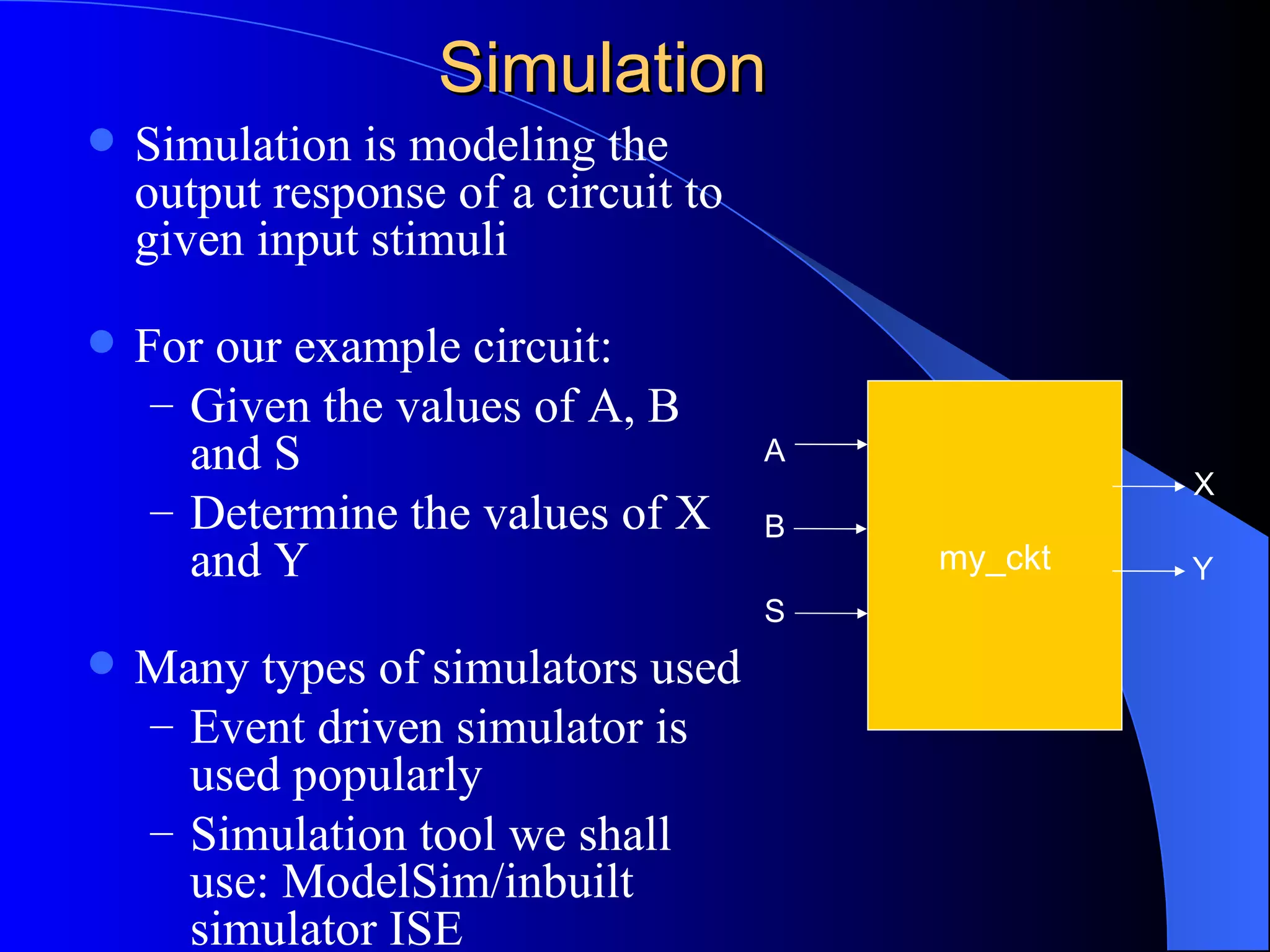
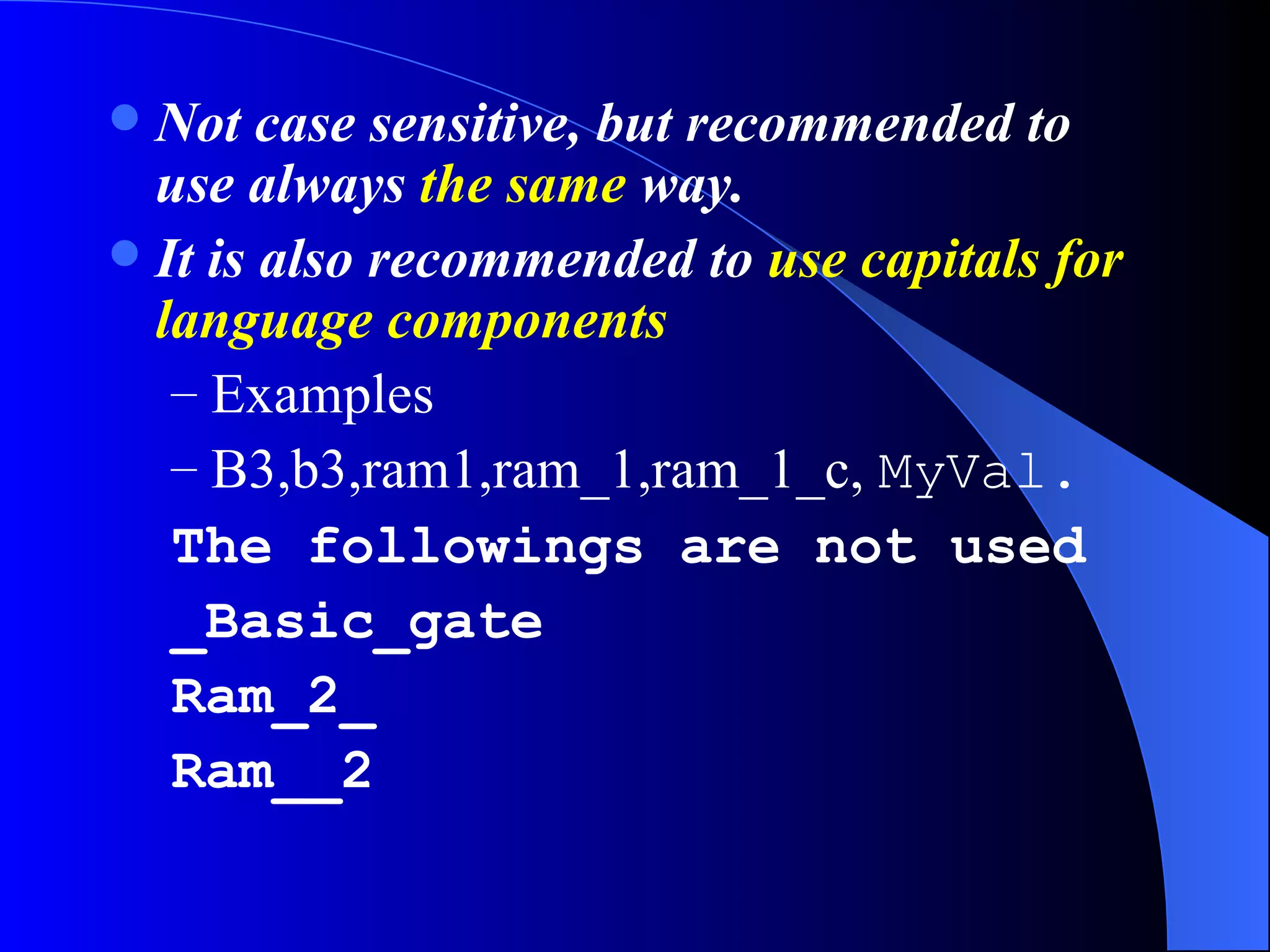
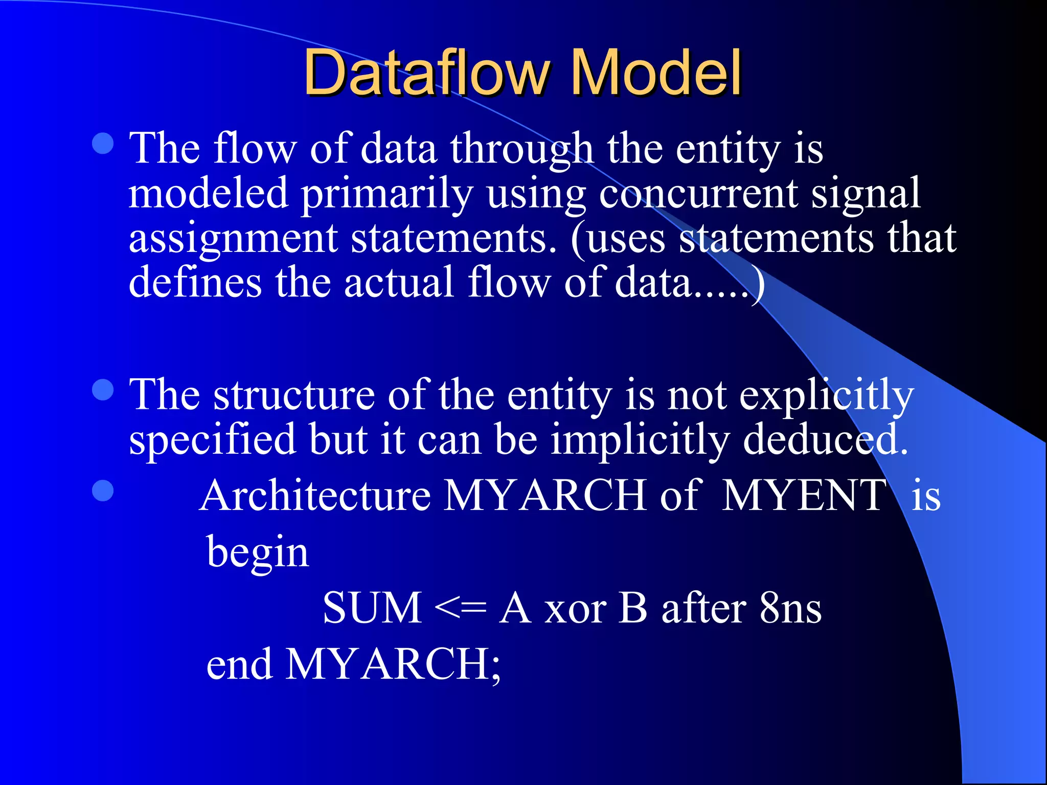
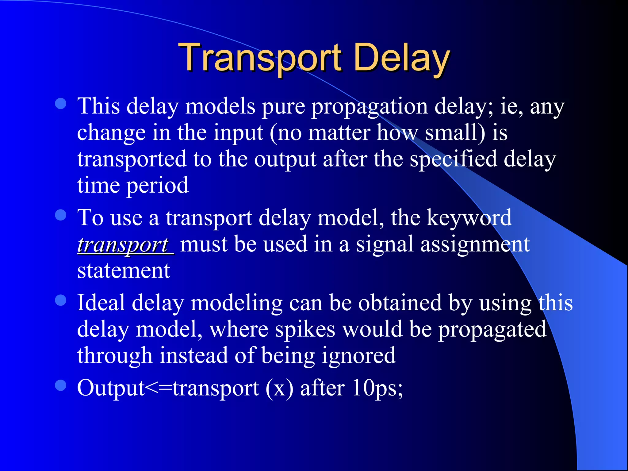
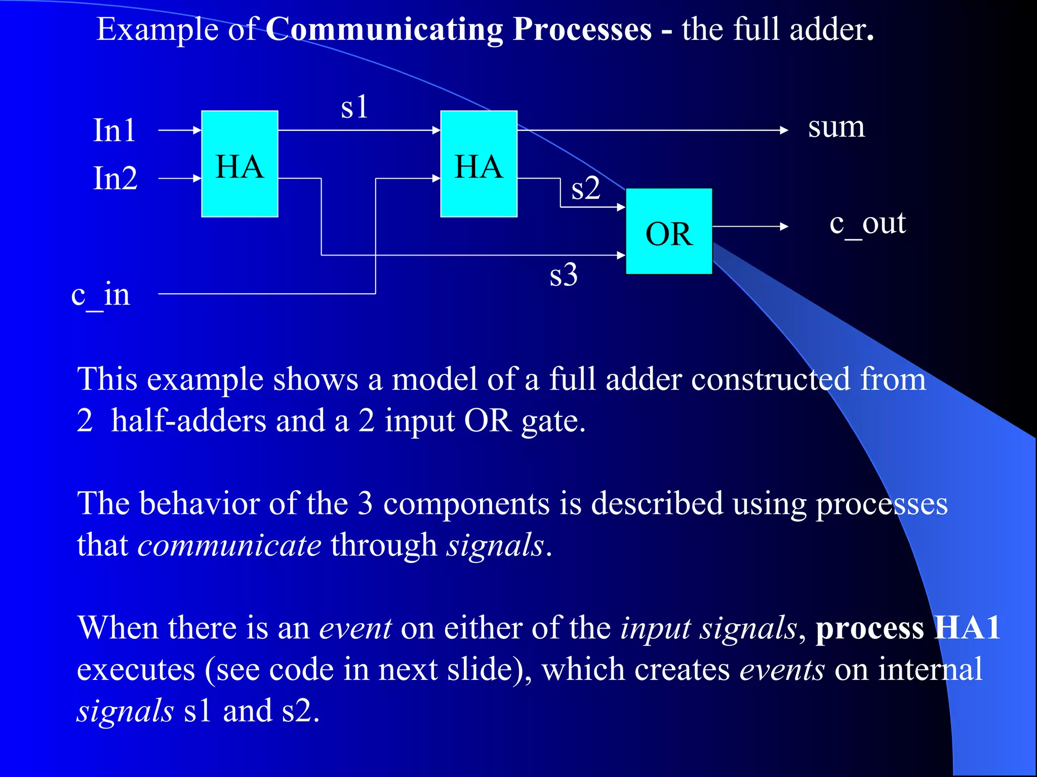
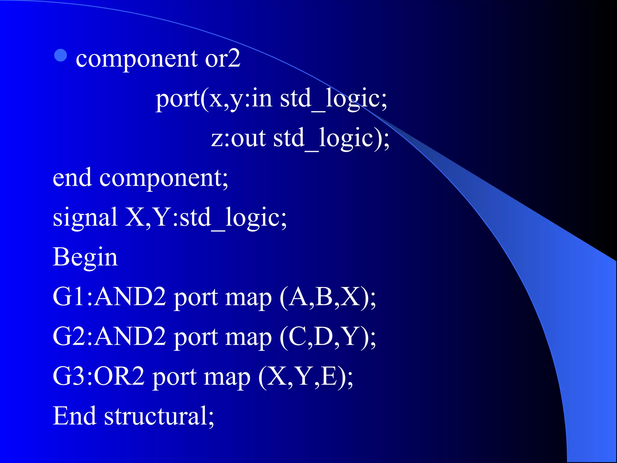
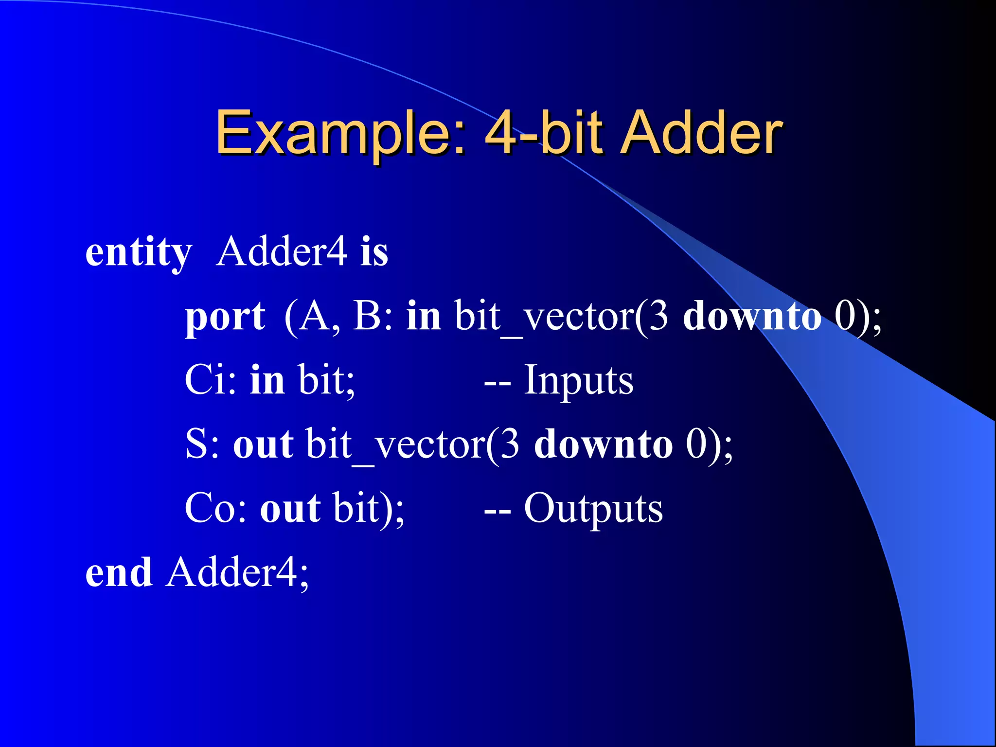
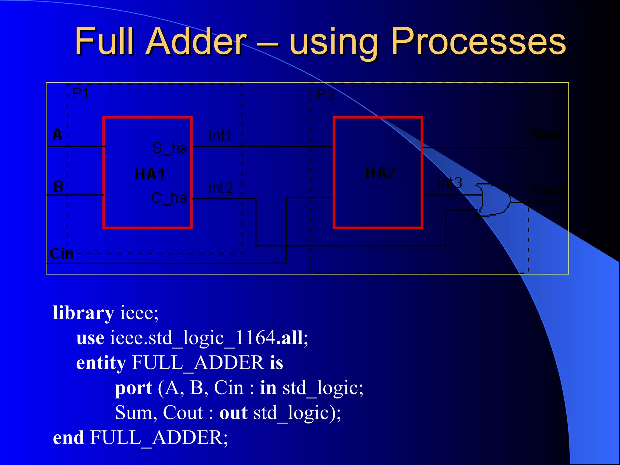
VHDL is a hardware description language used to model and design digital circuits. It can be used for simulation, synthesis, and verification of circuits. VHDL has different language elements like entities, architectures, processes, and packages that allow modeling at different levels of abstraction like behavioral, dataflow, and structural. Common data types in VHDL include std_logic, std_logic_vector, and integers. VHDL supports modeling concurrency using processes and signal assignments.
11. Additional standardized packages provide definitions of data types and expressions of timing data – IEEE 1164 (data types) – IEEE 1076.3 (numeric) – IEEE 1076.4 (timing)
12. Hardware description languages describe a system – Systems can be described from many different points of view • Behavior: what does it do? • Structure: what is it composed of? • Functional properties: how do I interface to it? • Physical properties: how fast is it? Usage (Using an HDL) Descriptions can used for – Simulation • Verification, performance evaluation – Synthesis • First step in hardware design
17. VHDL language elements VHDL is composed of language building blocks that consist of more than 75 reserved words and about 200 descriptive words or word combinations
18. Reserved VHDL keywords VARIABLE WAIT WHEN WHILE WITH XNOR XOR RETURN SELECT SEVERITY SIGNAL SHARED SLA SLL SRA SRL SUBTYPE THEN TO TRANSPORT TYPE UNAFFECTED UNITS UNTIL USE OF ON OPEN OR OTHERS OUT PACKAGE PORT POSTPONED PROCEDURE PROCESS PURE RANGE RECORD REGISTER REM REPORT ROL ROR IN INERTIAL INOUT IS LABEL LIBRARY LINKAGE LITERAL LOOP MAP MOD NAND NEW NEXT NOR NOT NULL DISCONNECT DOWNTO ELSE ELSIF END ENTITY EXIT FILE FOR FUNCTION GENERATE GENERIC GROUP GUARDED IF IMPURE ABS ACCESS AFTER ALIAS ALL AND ARCHITECTURE ARRAY ASSERT ATTRIBUTE BEGIN BLOCK BODY BUFFER BUS CASE COMPONENT CONFIGURATION CONSTANT
19.
20.
21.
22.
23.
24.
25.
26.
27.
28.
29.
30.
31.
32.
33.
34.
35.
36.
37.
38. Example of Communicating Processes - the full adder . This example shows a model of a full adder constructed from 2 half-adders and a 2 input OR gate. The behavior of the 3 components is described using processes that communicate through signals . When there is an event on either of the input signals , process HA1 executes (see code in next slide), which creates events on internal signals s1 and s2. In1 In2 s1 c_in sum c_out HA HA OR s2 s3
39. library IEEE; use IEEE.std_logic_1164.all; entity full_adder is port (in1, in2, c_in: in std_ulogic; sum, c_out: out std_ulogic); end full_adder; architecture dataflow of full_adder is signal s1, s2, s3 : std_ulogic; constant gate_delay: Time :=5 ns ; begin L1: s1<=(in1 xor in2) after gate_delay; L2: s2<=(c_in and s1) after gate_delay; L3: s3<=(in1 and in2) after gate_delay; L4: sum<=(s1 xor c_in) after gate_delay; L5: c_out<=(s2 or s3) after gate_delay; end dataflow; Architecture Body Architecture Declarative Statement
40.
41.
42.
43.
44.
45.
46.
47.
48.
49.
50.
51. Multiplexers A B Z A B I 3 A B’ I 2 A’ B’ I 0 Z Data inputs versus control inputs Use of muxes in control and data path 4-to-1 MUX I 0 I 1 I 2 I 3 A’ B I 1 A B Z 0 0 I 0 0 1 I 1 1 0 I 2 1 1 I 3 +