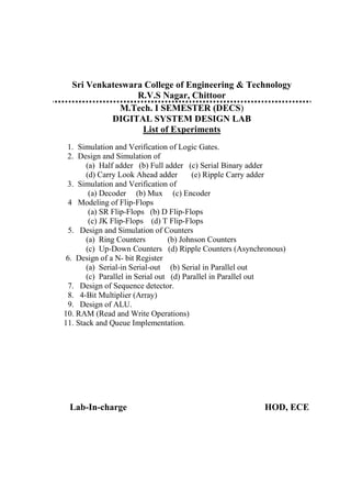
SlideShare a Scribd company logo
1 of 47
Download to read offline
Sri Venkateswara College of Engineering & Technology
R.V.S Nagar, Chittoor
M.Tech. I SEMESTER (DECS)
DIGITAL SYSTEM DESIGN LAB
List of Experiments
1. Simulation and Verification of Logic Gates.
2. Design and Simulation of
(a) Half adder (b) Full adder (c) Serial Binary adder
(d) Carry Look Ahead adder (e) Ripple Carry adder
3. Simulation and Verification of
(a) Decoder (b) Mux (c) Encoder
4 Modeling of Flip-Flops
(a) SR Flip-Flops (b) D Flip-Flops
(c) JK Flip-Flops (d) T Flip-Flops
5. Design and Simulation of Counters
(a) Ring Counters (b) Johnson Counters
(c) Up-Down Counters (d) Ripple Counters (Asynchronous)
6. Design of a N- bit Register
(a) Serial-in Serial-out (b) Serial in Parallel out
(c) Parallel in Serial out (d) Parallel in Parallel out
7. Design of Sequence detector.
8. 4-Bit Multiplier (Array)
9. Design of ALU.
10. RAM (Read and Write Operations)
11. Stack and Queue Implementation.
Lab-In-charge HOD, ECE
LOGIC GATES
Ex. No : 01
AIM :-
To write a VHDL Code for realizing Gates
• AND, OR, NOT, NAND, NOR, XOR, XNOR
And verify the results.
AND GATE
PROGRAM:-
library IEEE;
use IEEE.STD_LOGIC_1164.ALL;
use IEEE.STD_LOGIC_ARITH.ALL;
use IEEE.STD_LOGIC_UNSIGNED.ALL;
entity and2 is
Port ( a : in STD_LOGIC;
b : in STD_LOGIC;
c : out STD_LOGIC);
end and2;
architecture data_flow of and2 is
begin
c<=a and b;
end data_flow;
architecture behavioral of and2 is
begin
process(a,b)
begin
if a='1' and b='1'
then c<='1';
else c<='0';
end if;
end process;
end behavioral;
architecture structural of and2 is
component andx is
Port ( x : in STD_LOGIC;
y : in STD_LOGIC;
z : out STD_LOGIC);
end component;
begin
A1:andx port map(a,b,c);
end structural;
library IEEE;
use IEEE.STD_LOGIC_1164.ALL;
use IEEE.STD_LOGIC_ARITH.ALL;
use IEEE.STD_LOGIC_UNSIGNED.ALL;
entity andx is
Port ( x : in STD_LOGIC;
y : in STD_LOGIC;
z : out STD_LOGIC);
end andx;
architecture andx of andx is
begin
z<=x and y;
end andx;
OR GATE
PROGRAM:-
library IEEE;
use IEEE.STD_LOGIC_1164.ALL;
use IEEE.STD_LOGIC_ARITH.ALL;
use IEEE.STD_LOGIC_UNSIGNED.ALL;
entity or2 is
Port ( a : in STD_LOGIC;
b : in STD_LOGIC;
c : out STD_LOGIC);
end or2;
architecture data_flow of or2 is
begin
c<=a or b;
end data_flow;
architecture behavioral of or2 is
begin
process(a,b)
begin
if a='0' and b='0'
then c<='0';
else c<='1';
end if;
end process;
end behavioral;
architecture structural of or2 is
component orx is
Port ( x : in STD_LOGIC;
y : in STD_LOGIC;
z : out STD_LOGIC);
end component;
begin
A1:orx port map(a,b,c);
end structural;
library IEEE;
use IEEE.STD_LOGIC_1164.ALL;
use IEEE.STD_LOGIC_ARITH.ALL;
use IEEE.STD_LOGIC_UNSIGNED.ALL;
entity orx is
Port ( x : in STD_LOGIC;
y : in STD_LOGIC;
z : out STD_LOGIC);
end orx;
architecture orx of orx is
begin
z<=x or y;
end orx;
NOT GATE
PROGRAM:-
library IEEE;
use IEEE.STD_LOGIC_1164.ALL;
use IEEE.STD_LOGIC_ARITH.ALL;
use IEEE.STD_LOGIC_UNSIGNED.ALL;
entity not1 is Port ( a : in STD_LOGIC;
b : out STD_LOGIC);
end not1;
architecture data_flow of not1 is
begin
b<=not a;
end data_flow;
architecture behavioral of not1 is
begin
process(a)
begin
if a='0'
then b<='1';
else b<='0';
end if;
end process;
end behavioral;
architecture structural of not1 is
component notx is
Port ( x : in STD_LOGIC;
y : out STD_LOGIC);
end component;
begin
A1:notx port map(a,b);
end structural;
library IEEE;
use IEEE.STD_LOGIC_1164.ALL;
use IEEE.STD_LOGIC_ARITH.ALL;
use IEEE.STD_LOGIC_UNSIGNED.ALL;
entity notx is
Port ( x : in STD_LOGIC;
y : out STD_LOGIC);
end notx;
architecture notx of notx is
begin y<=not x;
end notx;
NAND GATE
PROGRAM:-
library IEEE;
use IEEE.STD_LOGIC_1164.ALL;
use IEEE.STD_LOGIC_ARITH.ALL;
use IEEE.STD_LOGIC_UNSIGNED.ALL;
entity nand2 is
Port ( a : in STD_LOGIC;
b : in STD_LOGIC;
c : out STD_LOGIC);
end nand2;
architecture data_flow of nand2 is
begin
c<=a nand b;
end data_flow;
architecture behavioral of nand2 is
begin
process(a,b)
begin
if a='1' and b='1'
then c<='0';
else c<='1';
end if;
end process;
end behavioral;
architecture structural of nand2 is
component nandx is
Port ( x : in STD_LOGIC;
y : in STD_LOGIC;
z : out STD_LOGIC);
end component;
begin
A1:nandx port map(a,b,c);
end structural;
library IEEE;
use IEEE.STD_LOGIC_1164.ALL;
use IEEE.STD_LOGIC_ARITH.ALL;
use IEEE.STD_LOGIC_UNSIGNED.ALL;
entity nandx is
Port ( x : in STD_LOGIC;
y : in STD_LOGIC;
z : out STD_LOGIC);
end nandx;
architecture nandx of nandx is
begin
z<=x nand y;
end nandx;
NOR GATE
PROGRAM:-
library IEEE;
use IEEE.STD_LOGIC_1164.ALL;
use IEEE.STD_LOGIC_ARITH.ALL;
use IEEE.STD_LOGIC_UNSIGNED.ALL;
entity nor2 is
Port ( a : in STD_LOGIC;
b : in STD_LOGIC;
c : out STD_LOGIC);
end nor2;
architecture data_flow of nor2 is
begin
c<=a nor b;
end data_flow;
architecture behavioral of nor2 is
begin
process(a,b)
begin
if a='0' and b='0'
then c<='1';
else c<='0';
end if;
end process;
end behavioral;
architecture structural of nor2 is
component norx is
Port ( x : in STD_LOGIC;
y : in STD_LOGIC;
z : out STD_LOGIC);
end component;
begin
A1:norx port map(a,b,c);
end structural;
library IEEE;
use IEEE.STD_LOGIC_1164.ALL;
use IEEE.STD_LOGIC_ARITH.ALL;
use IEEE.STD_LOGIC_UNSIGNED.ALL;
entity norx is
Port ( x : in STD_LOGIC;
y : in STD_LOGIC;
z : out STD_LOGIC);
end norx;
architecture norx of norx is
begin
z<=x nor y;
end norx;
XOR GATE
PROGRAM:-
library IEEE;
use IEEE.STD_LOGIC_1164.ALL;
use IEEE.STD_LOGIC_ARITH.ALL;
use IEEE.STD_LOGIC_UNSIGNED.ALL;
entity xor2 is
Port ( a : in STD_LOGIC;
b : in STD_LOGIC;
c : out STD_LOGIC);
end xor2;
architecture data_flow of xor2 is
begin
c<=a xor b;
end data_flow;
architecture behavioral of xor2 is
begin
process(a,b)
begin
if a=b
then c<='0';
else c<='1';
end if;
end process;
end behavioral;
architecture structural of xor2 is
component xorx is
Port ( x : in STD_LOGIC;
y : in STD_LOGIC;
z : out STD_LOGIC);
end component;
begin
A1:xorx port map(a,b,c);
end structural;
library IEEE;
use IEEE.STD_LOGIC_1164.ALL;
use IEEE.STD_LOGIC_ARITH.ALL;
use IEEE.STD_LOGIC_UNSIGNED.ALL;
entity xorx is
Port ( x : in STD_LOGIC;
y : in STD_LOGIC;
z : out STD_LOGIC);
end xorx;
architecture xorx of xorx is
begin
z<=x xor y;
end xorx;
XNOR GATE
PROGRAM:-
library IEEE;
use IEEE.STD_LOGIC_1164.ALL;
use IEEE.STD_LOGIC_ARITH.ALL;
use IEEE.STD_LOGIC_UNSIGNED.ALL;
entity xnor2 is
Port ( a : in STD_LOGIC;
b : in STD_LOGIC;
c : out STD_LOGIC);
end xnor2;
architecture data_flow of xnor2 is
begin
c<=a xnor b;
end data_flow;
architecture behavioral of xnor2 is
begin
process(a,b)
begin
if a=b
then c<='1';
else c<='0';
end if;
end process;
end behavioral;
architecture structural of xnor2 is
component xnorx is
Port ( x : in STD_LOGIC;
y : in STD_LOGIC;
z : out STD_LOGIC);
end component;
begin
A1:xnorx port map(a,b,c);
end structural;
library IEEE;
use IEEE.STD_LOGIC_1164.ALL;
use IEEE.STD_LOGIC_ARITH.ALL;
use IEEE.STD_LOGIC_UNSIGNED.ALL;
entity xnorx is
Port ( x : in STD_LOGIC;
y : in STD_LOGIC;
z : out STD_LOGIC);
end xnorx;
architecture xnorx of xnorx is
begin
z<=x xnor y;
end xnorx;
MODELING OF ADDERS
Ex. No : 02
AIM :-
To write a VHDL Code for
• Half adder
• Full adder
• ripple carry adder
• carry look ahead adder
• serial adder
And verify the results.
HALF ADDER
PROGRAM:-
library IEEE;
use IEEE.STD_LOGIC_1164.ALL;
use IEEE.STD_LOGIC_ARITH.ALL;
use IEEE.STD_LOGIC_UNSIGNED.ALL;
entity ha is
Port ( a : in STD_LOGIC;
b : in STD_LOGIC;
sum: out STD_LOGIC;
carry: out STD_LOGIC);
end ha;
architecture data_flow of ha is
begin
sum<=a xor b;
carry<= a and b;
end data_flow;
architecture behavioral of ha is
begin
process(a,b)
begin
if a=b
then sum<='0';
else sum<='1';
end if;
if a='1' and b='1'
then carry<='1';
else carry<='0';
end if;
end process;
end behavioral;
architecture structural of ha is
component xorx is
Port ( x : in STD_LOGIC;
y : in STD_LOGIC;
z : out STD_LOGIC);
end component;
component andx is
Port ( x : in STD_LOGIC;
y : in STD_LOGIC;
z : out STD_LOGIC);
end component;
begin
x1:xorx port map(a,b,sum);
A1:andx port map(a,b,carry);
end structural;
FULL ADDER
PROGRAM:-
library IEEE;
use IEEE.std_logic_1164.all;
entity adder is
port (a : in std_logic;
b : in std_logic;
cin : in std_logic;
sum : out std_logic;
cout : out std_logic);
end adder;
-- description of adder using concurrent signal assignments
architecture rtl of adder is
begin
sum <= (a xor b) xor cin;
cout <= (a and b) or (cin and a) or (cin and b);
end rtl;
-- description of adder using component instantiation statements
use work.gates.all;
architecture structural of adder is
signal xor1_out,
and1_out,
and2_out,
or1_out : std_logic;
begin
xor1: xorg port map(
in1 => a,
in2 => b,
out1 => xor1_out);
xor2: xorg port map(
in1 => xor1_out,
in2 => cin,
out1 => sum);
and1: andg port map(
in1 => a,
in2 => b,
out1 => and1_out);
or1: org port map(
in1 => a,
in2 => b,
out1 => or1_out);
and2: andg port map(
in1 => cin,
in2 => or1_out,
out1 => and2_out);
or2: org port map(
in1 => and1_out,
in2 => and2_out,
out1 => cout);
end structural;
------------------------------------------------------------------------
-- N-bit adder
-- The width of the adder is determined by generic N
------------------------------------------------------------------------
library IEEE;
use IEEE.std_logic_1164.all;
entity adderN is
generic(N : integer := 16);
port (a : in std_logic_vector(N downto 1);
b : in std_logic_vector(N downto 1);
cin : in std_logic;
sum : out std_logic_vector(N downto 1);
cout : out std_logic);
end adderN;
-- structural implementation of the N-bit adder
architecture structural of adderN is
component adder
port (a : in std_logic;
b : in std_logic;
cin : in std_logic;
sum : out std_logic;
cout : out std_logic);
end component;
signal carry : std_logic_vector(0 to N);
begin
carry(0) <= cin;
cout <= carry(N);
-- instantiate a single-bit adder N times
gen: for I in 1 to N generate
add: adder port map(
a => a(I),
b => b(I),
cin => carry(I - 1),
sum => sum(I),
cout => carry(I));
end generate;
end structural;
-- behavioral implementation of the N-bit adder
architecture behavioral of adderN is
begin
p1: process(a, b, cin)
variable vsum : std_logic_vector(N downto 1);
variable carry : std_logic;
begin
carry := cin;
for i in 1 to N loop
vsum(i) := (a(i) xor b(i)) xor carry;
carry := (a(i) and b(i)) or (carry and (a(i) or b(i)));
end loop;
sum <= vsum;
cout <= carry;
end process p1;
end behavioral;
RIPPLE CARRY ADDER
PROGRAM:-
library IEEE;
Use IEEE.STD_LOGIC_1164.All;
Use IEEE.STD_LOGIC_ARITH.All;
Use IEEE.STD_LOGIC_UNSIGNED.All;
entity rea is
Port (a: in std_logic _vector (3 downto 0);
b: in std_logic _vector (3 downto 0);
ci:in std_logic;
s: out std_logic _vector (3 downto 0);
co:in out std_logic);
end rea;
architecture structural of rea is
signal c:std_ logic vector(3 downto 1);
component fa is
port (a,b,cin: in std_logic;
s : out std_logic;
cout: in out std_logic);
end component;
begin
f1: fa port map( a(0), b(0), ci, s(0),c(1));
f2: fa port map(a(1), b(1), c(1), s(1),c(2));
f3: fa port map(a(2), b(2), c(2), s(2),c(3));
f4: fa port map(1)p(a(3), b(3), c(3), s(3),c(0));
end structural;
CARRY LOOK AHEAD ADDER
PROGRAM:-
library IEEE;
Use IEEE.STD_LOGIC_1164.All;
Use IEEE.STD_LOGIC_ARITH.All;
Use IEEE.STD_LOGIC_UNSIGNED.All;
entity carry_look_ahead is
Port (a: in std_logic _vector(3 downto 0);
b : in std_logic _vector(3 downto 0);
co : out std_logic;
c : inout std_logic _vector(4 downto 0);
s : out std_logic _vector(3 downto 0);
end carry_look_ahead;
architecture structural of carry_look_ahead is
signal p,g:std_ logic _vector(3 downto 0);
signal r : std_ logic_ vector(6 downto 0);
signal i : integer;
begin
processor(a,b,c,p,g,r)
begin
l1 : for i in 0 to 3 loop
p(i)<=a(i) xor b(i);
g(i)<=a(i) and b(i);
c(0)<=’0’;
end loop l1;
r(0)<=p(2)and g(1);
r(1)<=p(2)and p(1)and g(0);
r(2)<=p(2)and p(1)and p(0)and c(0);
r(3)<=p(3)and g(2);
r(4)<=p(3)and p(2)and g(1);
r(5)<=p(3)and p(2)and p(1)and g(0);
r(6)<=p(3)and p(2)and p(1)and p(0) and c(0);
c(1)<=g(0)or ( p(0) and c(0));
c(2)<=g(1)or ( p(1) and g(0)) or( p(1)and ( p(0) and c(0));
c(3)<=g(2)or r(0) or r(1) or r(2);
c(4)<=g(3)or r(3) or r(4) or r(5) or r(6);
l2: for i in 0 to 3 loop
s(i)<=p(i) xor c(i);
end loop l2;
c(0)<=c(4);
end process;
end Behavioral;
SERIAL ADDER
PROGRAM:-
library IEEE;
Use IEEE.STD_LOGIC_1164.All;
Use IEEE.STD_LOGIC_ARITH.All;
Use IEEE.STD_LOGIC_UNSIGNED.All;
entity serial_adder is
Port (x: in std_logic _vector(3 downto 0);
y : in std_logic _vector(3 downto 0);
clk : in std_logic;
ce:in std_logic;
cout : inout std_logic
s : out std_logic
end serial_adder;
architecture structural of serial_adder is
signal c:std_ logic_ vector(4 downto 0);
signal i : integer;
begin
processor(clk,x,y)
begin
if (ce’event and ce =’1’)then
c(0)<=’0’;
s<=’0’;
i<=’0’;
end if;
if (ce’event and clk =’1’)then
s<=(x(i)xor y(i) xor c(i);
c(i+1)<=(x(i)and y(i))or (y(i)and c(i))or (c(i)and x(i));
i<=i+1;
end if;
else
i<=0;
end if;
cout<=c(4);
end process;
end Behavioral;
EX.No:- 03
3:8 DECODER
AIM: To write and simulate a vhdl program for a 3 to 8 decoder and verify the
results
PROGRAM:-
library ieee;
use ieee.std_logic_1164.all;
use ieee.std_logic_arith.all;
use ieee.std_logic_unsigned.all;
entity dc_counter is
port(clk:in std_logic;
q:inout std_logic_vector(3 downto 0):="0000");
end dc_counter;
architecture behave of dc_counter is
begin
process(clk)
begin
if(clk'event and clk='1')then
if(q="1001")then
q<="0000";
else
q<=q+1;
end if;
end if;
end process;
end behave;
8x1 MULTIPLEXER
AIM:- To write and simulate aModelsim( VHDL) program for 8x1 Multiplexer.
PROGRAM:-
library ieee;
use ieee.std_logic_1164.all;
entity mx is
port(i:in std_logic_vector(7 downto 0);
s:in std_logic_vector(2 downto 0);
y:out std_logic);
end mx;
architecture archi of mx is
begin
process(i,s)
begin
if(s="000") then y<=i(0);
elsif(s="001") then y<=i(1);
elsif(s="010") then y<=i(2);
elsif(s="011") then y<=i(3);
elsif(s="100") then y<=i(4);
elsif(s="101") then y<=i(5);
elsif(s="110") then y<=i(6);
elsif(s="111") then y<=i(7);
end if;
end process;
end archi;
MODELING OF FLIP - FLOPS
Ex. No : 04
AIM : -
To write a VHDL Code for
• SR Flip-Flop
• D Flip-Flop
• JK Flip-Flop
• T Flip-Flop
And verify the results.
SR - FLIP - FLOP
PROGRAM:-
library IEEE;
Use IEEE.STD_LOGIC_1164.All;
Use IEEE.STD_LOGIC_ARITH.All;
Use IEEE.STD_LOGIC_UNSIGNED.All;
entity srff is
Port (s : in std_logic;
r : in std_logic;
clk : in std_logic;
q : in out std_logic;
qbar : in out std_logic);
end srff;
architecture Behavioral of srff is
begin
Process (s,clk,r)
begin
if (clk’event and clk =’1’)then
if(s=’0’and r=’0’)then
q<=q;
qbar<=qbar;
elsif(s=’1’and r=’0’)then
q<=’1’;
qbar<=’0’;
elsif(s=’0’and r=’1’)then
q<=’0’;
qbar<=’1’;
else
q<=not q ;
qbar<=not qbar;
end if:
else
q<=q;
qbar<=qbar;
end if:
end process;
end Behavioral;
architecture data_flow of sr_ff is
signal s1,s2:std_ logic;
begin
s1<=s nand clk;
s2<=r nand clk;
q<=s1 nand qbar;
qbar<=s2 nand q;
end data_flow;
architecture structural of srff is
signal s1,s2:std_ logic;
component nand2 is
port (a,b: in std_logic;
c : out std_logic);
end component;
begin
n1: nand2 port map(s,clk,s1);
n2: nand2 port map(r,clk,s2);
n3: nand2 port map(s1,qbar,q);
n4: nand2 port map(s2,q,qbar);
end structural;
D - FLIP - FLOP
PROGRAM:-
library IEEE;
Use IEEE.STD_LOGIC_1164.All;
Use IEEE.STD_LOGIC_ARITH.All;
Use IEEE.STD_LOGIC_UNSIGNED.All;
entity dff is
Port (d : in std_logic;
clk : in std_logic;
q : in out std_logic;
qbar : in out std_logic);
end dff;
architecture Behavioral of dff is
begin
Process (d,clk)
Begin
if (clk’event and clk =’1’)then
if(d=’0’)then
q<=’0’;
qbar<=’1’;
else
q<=’1’;
qbar<=’0’;
end if:
else
q<=q;
qbar<= qbar;
end if:
end process;
end Behavioral;
architecture data_flow of d_ff is
signal s1,s2:std_ logic;
begin
s1<=d nand clk;
s2<=not d nand clk;
q<=s1 nand qbar;
qbar<=s2 nand q;
end data_flow;
architecture structural of d_ff is
signal s1,s2,s3:std_ logic;
component nand2 is
port (a,b: in std_logic;
c : out std_logic);
end component;
component not1 is
port (a: in std_logic;
c : out std_logic);
end component;
begin
x1: not1 port map(d,s3);
n1: nand2 port map(d,clk,s1);
n2: nand2 port map(s3,clk,s2);
n3: nand2 port map(s1,qbar,q);
n4: nand2 port map(s2,q,qbar);
end structural;
JK - FLIP - FLOP
PROGRAM:-
library IEEE;
Use IEEE.STD_LOGIC_1164.All;
Use IEEE.STD_LOGIC_ARITH.All;
Use IEEE.STD_LOGIC_UNSIGNED.All;
entity jkff is
Port (j : in std_logic;
k : in std_logic;
clk : in std_logic;
q : in out std_logic;
qbar : in out std_logic);
end jkff;
architecture Behavioral of jkff is
begin
Process (j,clk,k)
begin
if (clk’event and clk =’1’)then
if(j=’0’and k=’0’)then
q<=q;
qbar<=qbar;
elsif(j=’0’and k=’1’)then
q<=’0’;
qbar<=’1’;
elsif(j=’1’and k=’0’)then
q<=’1’;
qbar<=’0’;
else
q<=not q ;
qbar<=not qbar;
end if:
else
q<=q;
qbar<=qbar;
end if:
end process;
end Behavioral;
architecture data_flow of jk_ff is
signal s1,s2:std_ logic;
begin
s1<=k and clk and q;
s2<=j and clk and qbar;
q<=s1 nor qbar;
qbar<=s2 nor q;
end data_flow;
architecture structural of jk_ff is
signal s1,s2:std_ logic;
component nor2 is
port (a,b: in std_logic;
c : out std_logic);
end component;
begin
component and3 is
port (a,b,c: in std_logic;
d : out std_logic);
end component;
begin
x1: and3 port map(k,clk,q,s1);
x2: and3 port map(j,clk,qbar,s2);
x3: nor2 port map(s1,qbar,q);
x4: and2 port map(s2,q,qbar);
end structural;
T - FLIP - FLOP
PROGRAM:-
library IEEE;
Use IEEE.STD_LOGIC_1164.All;
Use IEEE.STD_LOGIC_ARITH.All;
Use IEEE.STD_LOGIC_UNSIGNED.All;
entity tff is
Port (t : in std_logic;
clk : in std_logic;
q : in out std_logic;
qbar : in out std_logic);
end tff;
architecture Behavioral of tff is
begin
Process (t,clk,)
begin
if (clk’event and clk =’1’)then
if(t=’0’)then
q<=q;
qbar<=qbar;
else
q<=not q ;
qbar<=not qbar;
end if:
else
q<=q;
qbar<=qbar;
end if:
end process;
end Behavioral;
architecture data_flow of t_ff is
signal s1,s2:std_ logic;
begin
s1<=t and clk and q;
s2<=t and clk and qbar;
q<=s1 nor qbar;
qbar<=s2 nor q;
end data_flow;
architecture structural of t_ff is
signal s1,s2 : std_ logic;
component nor2 is
port (a,b: in std_logic;
c : out std_logic);
end component;
begin
component and3 is
port (a,b,c: in std_logic;
d : out std_logic);
end component;
begin
x1: and3 port map(t,clk,q,s1);
x2: and3 port map(t,clk,qbar,s2);
x3: nor2 port map(s1,qbar,q);
x4: and2 port map(s2,q,qbar);
end structural;
DESIGN AND SIMULATION OF COUNTERS
Ex. No : 05
AIM :-
To write a VHDL Code for
• Ring Counters
• Johnson Counters
• Up-Down Counters
• Ripple Counters (Asynchronous)
And verify the results.
BCD COUNTER
PROGRAM:
library IEEE;
Use IEEE.STD_LOGIC_1164.All;
Use IEEE.STD_LOGIC_ARITH.All;
Use IEEE.STD_LOGIC_UNSIGNED.All;
entity mod_n_coun is
Port (ce: in std_logic ;
clk: in std_logic;
q:in out std_logic _vector (3 downto 0));
end mod_n_coun ;
architecture Behavioral of mod_n_coun is
begin
Process (ce,clk);
begin
if (ce’event and ce =’1’)then
q<=”0000”;
end if:
if (clk’event and clk =’1’)then
if (ce=’1’)then
q<=q+1;
end if;
if (q>=”1001”)then
q<=”0000”;
end if;
end if;
end process;
end Behavioral;
BINARY UP DOWN COUNTER
PROGRAM:-
library IEEE;
Use IEEE.STD_LOGIC_1164.All;
Use IEEE.STD_LOGIC_ARITH.All;
Use IEEE.STD_LOGIC_UNSIGNED.All;
entity bin_up_down is
Port (up: in std_logic ;
down: in std_logic;
ce: in std_logic ;
clk: in std_logic;
q:in out std_logic _vector (3 downto 0));
end bin_up_down;
architecture Behavioral of bin_up_down is
begin
Process (up, down, ce, clk);
begin
if (ce’event and ce =’1’)then
q<=”0000”;
end if:
if (clk’event and clk =’1’)then
if (up=’1’)then
q<=q+1;
else if(down=’1’)then
q<=q-1;
end if;
end if;
end process;
end Behavioral;
ASYNCHRONOUS COUNTER
PROGRAM:-
library IEEE;
Use IEEE.STD_LOGIC_1164.All;
Use IEEE.STD_LOGIC_ARITH.All;
Use IEEE.STD_LOGIC_UNSIGNED.All;
entity asy_count is
Port (ce: in std_logic;
clk: in std_logic;
n:in std_logic _vector (3 downto 0);
q:in out std_logic _vector (3 downto 0));
end asy_count;
architecture Behavioral of asy_count is
begin
Process (ce, clk,q);
begin
if (ce’event and ce =’1’)then
q<=”0000”;
end if:
if(q<n)then
if (clk’event and clk =’1’)then
q(0)<=not q(0);
if (q(0) =’1’)then
q(1)<=not q(1);
if (q(1) =’1’)then
q(2)<=not q(2);
if (q(2) =’1’)then
q(3)<=not q(3);
end if;
end if;
end if;
end if;
else
q<=”0000”;
end if;
end process;
end Behavioral;
MODELING OF SHIFT REGISTERS COUNTERS
Ex. No : 06
AIM :-
To write VHDL Program for realizing Shift Registers
• Serial-in Serial-out
• Serial in Parallel out
• Parallel in Serial out
• Parallel in Parallel out
And verify the results.
SHIFT REGISTERS
Serial in serial out (SISO)
PROGRAM:
library IEEE;
Use IEEE.STD_LOGIC_1164.All;
Use IEEE.STD_LOGIC_ARITH.All;
Use IEEE.STD_LOGIC_UNSIGNED.All;
Entity siso is
Port (si: in std_logic;
clk: in std_logic;
so:in out std_logic);
end siso;
architecture structural of siso is
component d_ff is
Port( d,clk: in std_logic;
q,qbar :in out std_logic);
end component;
Signal a1, a2, a3, d1, d2, d3, d4:std_logic;
begin
11:d_ff port map (si, clk, a1, d1);
12:d_ff port map (a1, clk, a2, d2);
13:d_ff port map (a2, clk, a3, d3);
14:d_ff port map (a3, clk, so, d4);
end structural;
SIPO
PROGRAM:-
library IEEE;
Use IEEE.STD_LOGIC_1164.All;
Use IEEE.STD_LOGIC_ARITH.All;
Use IEEE.STD_LOGIC_UNSIGNED.All;
Entity sipo is
Port (si: in std_logic;
clk: in std_logic;
po:in out std_logic_vector(3 downto 0));
end sipo;
architecture structural of sipo is
signal d:std _logic_ vector(4 downto 0);
component d_ff
Port (d,clk: in std_logic;
q,qbar :in out std_logic);
end component;
begin
a1:d_ff port map (si, clk, po(3),d(3));
a2:d_ff port map( po(3), clk, po(2),d(2));
a3:d_ff port map (po(2), clk, po(1),d(1));
a4:d_ff port map (po(1), clk, po(0),d(0));
end structural;
PISO
PROGRAM:-
library IEEE;
Use IEEE.STD_LOGIC_1164.All;
Use IEEE.STD_LOGIC_ARITH.All;
Use IEEE.STD_LOGIC_UNSIGNED.All;
entity piso is
Port (pi: in std_logic _vector (3 downto 0);
c: in std_logic;
clk: in std_logic;
so:in out std_logic);
end piso;
architecture structural of piso is
signal d:std_ logic vector(3 downto 0);
signal q:std _logic vector(3 downto 1);
signal a:std_ logic vector(3 downto 1);
signal r:std _logic;
component d_ff is
Port (d,clk: in std_logic;
q,qbar :in out std_logic);
end component;
component aoi is
Port (a,b,c,d: in std_logic;
c: out std_logic);
end component;
begin
a1:aio port map (q (3),r,c,pi(2)a(3));
a2:aio port map( q (2),r,c,pi(1)a(2));
a3:aio port map (q (1),r,c,pi(0)a(1));
11:d_ff port map( pi(3), clk, q(3),d(3));
12:d_ff port map(a(3), clk, q(2),d(2));
13:d_ff port map(a(2), clk, q(1),d(1));
14:d_ff port map(a(1), clk, so,d(0));
end structural;
PIPO
PROGRAM:-
library IEEE;
Use IEEE.STD_LOGIC_1164.All;
Use IEEE.STD_LOGIC_ARITH.All;
Use IEEE.STD_LOGIC_UNSIGNED.All;
entity pipo is
Port (pi: in std_logic _vector (3 downto 0);
clk: in std_logic;
po:in out std_logic _vector (3 downto 0));
end pipo;
architecture structural of pipo is
signal d:std_ logic vector(4 downto 0);
component d_ff is
Port (d,clk: in std_logic;
q,qbar :in out std_logic);
end component;
begin
11:d_ff port map( pi(3), clk, po(3),d(3));
12:d_ff port map( pi(2), clk, po(2),d(2));
13:d_ff port map( pi(1), clk, po(1),d(1));
14:d_ff port map( pi(0), clk, po(0),d(0));
end structural;
Serial in serial out (SISO)
Serial Input
Clk
Serial Out
Serial in Parallel out (SIPO)
Serial Input
Clk
Parallel Out
Q(n-2) Q(n-3) Q(0)Q(n-1)
Parallel in out Serial (PISO)
Parallel In
Clk
Serial Out
Parallel in Parallel out(PIPO)
Parallel In
Clk
Load
Parallel Out
SISO PIPO
SIN CLK SOUT
1 U
0 1
0 0
1 0
1 1
1 1
0 1
INPUT OUTPUT
SIN CLK
Q0 Q1 Q2 Q3
1 U U U U
0 1 U U U
0 0 1 U U
1 0 0 1 U
1 1 0 0 1
1 1 1 0 0
Q(n-2) Q(n-3) Q(0)Q(n-1)
PISO
PIPO
MOD-N BCD Counter
Q0
Q1
Clk
Q2
Q3
INPUT
OUTPUT
LOAD CLK IN0 IN1 IN1 IN1 SOUT
1 0 0 1 U
X 1 1 0 0 1
X 1 1 1 0 0
X 1 1 1 1 0
X 1 1 1 1 1
INPUT OUTPUT
LOAD CLK
10 11 I2 I3 Q0 Q1 Q2 Q3
X 1 0 0 1 U U U U
X 1 0 0 1 1 0 0 1
X 1 1 0 1 1 0 0 1
0 1 0 0 1 1 0 1
X 0 1 0 0 0 1 0 0
INPUT OUTPUT
SIN CLK
Q0 Q1 Q2 Q3
1 U U U U
0 1 U U U
0 0 1 U U
1 0 0 1 U
1 1 0 0 1
1 1 1 0 0
MOD-N
BCD
Counter
BINARY UP DOWN COUNTER
Q0
UP
DN Q1
Clk Q2
Q3
ASYNCHRONOUS COUNTER
Q0
Clk
Q1
Q0
Q2
Q1
Q3
Q2
CLR
BINARY
UP
DOWN
COUNTER
Asynchronous
Counter
MODELLING OF MULTIPLIERS
Ex. No : 08
AIM :-
To write VHDL Program for realizing multipliers like Array
Multiplier and verify the results.
PROGRAM:-
library IEEE;
Use IEEE.STD_LOGIC_1164.All;
Use IEEE.STD_LOGIC_ARITH.All;
Use IEEE.STD_LOGIC_UNSIGNED.All;
entity unsign_mul is
Port (x: in std_logic _vector(3 downto 0);
y : in std_logic _vector(3 downto 0);
l : in std_logic;
p : inout std_logic _vector(7 downto 0);
end unsign_mul;
architecture Behavioral of unsign_mul is
signal m : std_ logic_ vector(7 downto 0);
signal i : integer;
begin
processor(x,y,i)
begin
if (l’event and l =’1’)then
q<=”00000000”;
m<=”0000”&x;
i<=0;
else
qbar<=qbar;
if(i<4)then
if(y(i)=’1’)then
q<=p+m;
else
p<=p;
i<=i+1 after 50 ps;
m<=m(6 downto 0)&’0’;
end if;
end if;
end process;
end Behavioral;
RAM
Ex. No : 09
AIM :-
To write VHDL Program for RAM and verify the results.
PROGRAM:-
library ieee;
use ieee.std_logic_1164.all;
entity ram is
port(din:in std_logic_vector(7 downto 0);
rd,wr,clk:in std_logic;
locn:in integer range 0 to 7;
dout:out std_logic_vector(7 downto 0));
end ram;
architecture behav of ram is
type mem is array(integer range 0 to 7) of std_logic_vector(7 downto 0);
signal sram:mem;
begin
process(clk,rd,wr)
begin
if((rd and wr)/='1')then
if(clk'event and clk='1')then
if(rd='1')then
dout<=sram(locn);
else if(wr='1')then
sram(locn)<=din;
end if;
end if;
end if;
end if;
end process;
end behav;
STACK AND QUEUE IMPLEMENTATIONS
Ex. No : 10
AIM :-
To write VHDL Program for Stack and Queue Implementations
and verify the results.
PROGRAM:-
library ieee;
use ieee.std_logic_1164.all;
entity stack is
port ( rd,wr,clk,clr:in std_logic;
data: inout std_logic_vector(7 downto 0);
ful:out std_logic);
end stack;
architecture que of stack is
type store is array(natural range <>)of std_logic_vector(7 downto 0);
signal address: integer range 0 to 15;
signal memory:store(0 to 15);
begin
process (data ,rd ,wr,clr,clk)
begin
if clr='1' then
memory<=(others=>(others=>'0'));
ful<='0';
address<=0;
elsif(clk='1'and clk'event)then
if address=15 then
ful<='1';
else
memory(address)<=data;
address<=address+1;
end if;
elsif (rd='1')then
if (address=0)then
ful<='0';
else
data<=memory(address);
address<=address-1;
end if;
end if;
end process;
end que;
Digital system design lab manual

More Related Content

What's hot

Presentation on Flip Flop
Presentation  on Flip FlopPresentation  on Flip Flop
Presentation on Flip FlopNahian Ahmed
 
DIgital clock using verilog
DIgital clock using verilog DIgital clock using verilog
DIgital clock using verilog Abhishek Sainkar
 
Session 6 sv_randomization
Session 6 sv_randomizationSession 6 sv_randomization
Session 6 sv_randomizationNirav Desai
 
Modified booth's algorithm Part 2
Modified booth's algorithm Part 2Modified booth's algorithm Part 2
Modified booth's algorithm Part 2babuece
 
Lecture 5 Synchronous Sequential Logic
Lecture 5 Synchronous Sequential LogicLecture 5 Synchronous Sequential Logic
Lecture 5 Synchronous Sequential LogicJames Evangelos
 
Overview of digital design with Verilog HDL
Overview of digital design with Verilog HDLOverview of digital design with Verilog HDL
Overview of digital design with Verilog HDLanand hd
 
Contamination delay
Contamination delayContamination delay
Contamination delayNima Afraz
 
UVM Methodology Tutorial
UVM Methodology TutorialUVM Methodology Tutorial
UVM Methodology TutorialArrow Devices
 
Chapter 4 flip flop for students
Chapter 4 flip flop for studentsChapter 4 flip flop for students
Chapter 4 flip flop for studentsCT Sabariah Salihin
 
multiplexers and demultiplexers
 multiplexers and demultiplexers multiplexers and demultiplexers
multiplexers and demultiplexersUnsa Shakir
 
Clock divider by 3
Clock divider by 3Clock divider by 3
Clock divider by 3Ashok Reddy
 
Design of Elevator Controller using Verilog HDL
Design of Elevator Controller using Verilog HDLDesign of Elevator Controller using Verilog HDL
Design of Elevator Controller using Verilog HDLVishesh Thakur
 

What's hot (20)

Presentation on Flip Flop
Presentation  on Flip FlopPresentation  on Flip Flop
Presentation on Flip Flop
 
VERILOG CODE FOR Adder
VERILOG CODE FOR AdderVERILOG CODE FOR Adder
VERILOG CODE FOR Adder
 
Introduction to FPGAs
Introduction to FPGAsIntroduction to FPGAs
Introduction to FPGAs
 
DIgital clock using verilog
DIgital clock using verilog DIgital clock using verilog
DIgital clock using verilog
 
Session 6 sv_randomization
Session 6 sv_randomizationSession 6 sv_randomization
Session 6 sv_randomization
 
SEQUENTIAL CIRCUITS [Flip-flops and Latches]
SEQUENTIAL CIRCUITS [Flip-flops and Latches]SEQUENTIAL CIRCUITS [Flip-flops and Latches]
SEQUENTIAL CIRCUITS [Flip-flops and Latches]
 
Modified booth's algorithm Part 2
Modified booth's algorithm Part 2Modified booth's algorithm Part 2
Modified booth's algorithm Part 2
 
Lecture 5 Synchronous Sequential Logic
Lecture 5 Synchronous Sequential LogicLecture 5 Synchronous Sequential Logic
Lecture 5 Synchronous Sequential Logic
 
Overview of digital design with Verilog HDL
Overview of digital design with Verilog HDLOverview of digital design with Verilog HDL
Overview of digital design with Verilog HDL
 
Contamination delay
Contamination delayContamination delay
Contamination delay
 
UVM Methodology Tutorial
UVM Methodology TutorialUVM Methodology Tutorial
UVM Methodology Tutorial
 
Data Flow Modeling
Data Flow ModelingData Flow Modeling
Data Flow Modeling
 
Adder ppt
Adder pptAdder ppt
Adder ppt
 
Chapter 4 flip flop for students
Chapter 4 flip flop for studentsChapter 4 flip flop for students
Chapter 4 flip flop for students
 
4 bit add sub
4 bit add sub4 bit add sub
4 bit add sub
 
Verilog
VerilogVerilog
Verilog
 
Assembly 8086
Assembly 8086Assembly 8086
Assembly 8086
 
multiplexers and demultiplexers
 multiplexers and demultiplexers multiplexers and demultiplexers
multiplexers and demultiplexers
 
Clock divider by 3
Clock divider by 3Clock divider by 3
Clock divider by 3
 
Design of Elevator Controller using Verilog HDL
Design of Elevator Controller using Verilog HDLDesign of Elevator Controller using Verilog HDL
Design of Elevator Controller using Verilog HDL
 

Viewers also liked

M.TECH, ECE 2nd SEM LAB RECORD
M.TECH, ECE 2nd SEM LAB RECORD M.TECH, ECE 2nd SEM LAB RECORD
M.TECH, ECE 2nd SEM LAB RECORD Arif Ahmed
 
Design & implementation of high speed carry select adder
Design & implementation of high speed carry select adderDesign & implementation of high speed carry select adder
Design & implementation of high speed carry select adderssingh7603
 
Question 3 – what have you learnt from
Question 3 – what have you learnt fromQuestion 3 – what have you learnt from
Question 3 – what have you learnt fromnushy1993
 
P pt keys for good and happy life.
P pt keys for good and happy life.P pt keys for good and happy life.
P pt keys for good and happy life.Rajasekhar Dasari
 
Importance of history
Importance of historyImportance of history
Importance of historyping1973
 
Ths general biology unit 1 our environment living requirements notes_v1516
Ths general biology unit 1 our environment living requirements notes_v1516Ths general biology unit 1 our environment living requirements notes_v1516
Ths general biology unit 1 our environment living requirements notes_v1516rozeka01
 
7 Deadly Sins of Tech
7 Deadly Sins of Tech7 Deadly Sins of Tech
7 Deadly Sins of TechRob Dyke
 
Comm skills1
Comm skills1Comm skills1
Comm skills1Raj Kaur
 
S811 2.0 manual 18 09 def
S811 2.0 manual 18 09 defS811 2.0 manual 18 09 def
S811 2.0 manual 18 09 defserpentmrc
 
Gwiiyomi lyric
Gwiiyomi lyricGwiiyomi lyric
Gwiiyomi lyricPutri PW
 
Hsu Presentation
Hsu PresentationHsu Presentation
Hsu Presentationsealt
 
Jeffrey Sachs
Jeffrey SachsJeffrey Sachs
Jeffrey Sachsrosiem7
 
Guj engdictionary
Guj engdictionaryGuj engdictionary
Guj engdictionarynilay4561
 
OpenGL ES based UI Development on TI Platforms
OpenGL ES based UI Development on TI PlatformsOpenGL ES based UI Development on TI Platforms
OpenGL ES based UI Development on TI PlatformsPrabindh Sundareson
 
Jini new technology for a networked world
Jini new technology for a networked worldJini new technology for a networked world
Jini new technology for a networked worldSajan Sahu
 

Viewers also liked (20)

M.TECH, ECE 2nd SEM LAB RECORD
M.TECH, ECE 2nd SEM LAB RECORD M.TECH, ECE 2nd SEM LAB RECORD
M.TECH, ECE 2nd SEM LAB RECORD
 
Design & implementation of high speed carry select adder
Design & implementation of high speed carry select adderDesign & implementation of high speed carry select adder
Design & implementation of high speed carry select adder
 
De lab manual
De lab manualDe lab manual
De lab manual
 
Question 3 – what have you learnt from
Question 3 – what have you learnt fromQuestion 3 – what have you learnt from
Question 3 – what have you learnt from
 
P pt keys for good and happy life.
P pt keys for good and happy life.P pt keys for good and happy life.
P pt keys for good and happy life.
 
Importance of history
Importance of historyImportance of history
Importance of history
 
Ths general biology unit 1 our environment living requirements notes_v1516
Ths general biology unit 1 our environment living requirements notes_v1516Ths general biology unit 1 our environment living requirements notes_v1516
Ths general biology unit 1 our environment living requirements notes_v1516
 
7 Deadly Sins of Tech
7 Deadly Sins of Tech7 Deadly Sins of Tech
7 Deadly Sins of Tech
 
Getumhe ekologi
Getumhe ekologiGetumhe ekologi
Getumhe ekologi
 
Comm skills1
Comm skills1Comm skills1
Comm skills1
 
rajesh - Updated
rajesh - Updatedrajesh - Updated
rajesh - Updated
 
S811 2.0 manual 18 09 def
S811 2.0 manual 18 09 defS811 2.0 manual 18 09 def
S811 2.0 manual 18 09 def
 
Gwiiyomi lyric
Gwiiyomi lyricGwiiyomi lyric
Gwiiyomi lyric
 
Hsu Presentation
Hsu PresentationHsu Presentation
Hsu Presentation
 
Jeffrey Sachs
Jeffrey SachsJeffrey Sachs
Jeffrey Sachs
 
Guj engdictionary
Guj engdictionaryGuj engdictionary
Guj engdictionary
 
Ank 48
Ank 48Ank 48
Ank 48
 
OpenGL ES based UI Development on TI Platforms
OpenGL ES based UI Development on TI PlatformsOpenGL ES based UI Development on TI Platforms
OpenGL ES based UI Development on TI Platforms
 
Sxsf
SxsfSxsf
Sxsf
 
Jini new technology for a networked world
Jini new technology for a networked worldJini new technology for a networked world
Jini new technology for a networked world
 

Similar to Digital system design lab manual

Similar to Digital system design lab manual (20)

VHDL Programs
VHDL ProgramsVHDL Programs
VHDL Programs
 
Digital System Design Lab Report - VHDL ECE
Digital System Design Lab Report - VHDL ECEDigital System Design Lab Report - VHDL ECE
Digital System Design Lab Report - VHDL ECE
 
VHDL PROGRAMS FEW EXAMPLES
VHDL PROGRAMS FEW EXAMPLESVHDL PROGRAMS FEW EXAMPLES
VHDL PROGRAMS FEW EXAMPLES
 
Practical file
Practical filePractical file
Practical file
 
Presentation1.pdf
Presentation1.pdfPresentation1.pdf
Presentation1.pdf
 
Digital system design practical file
Digital system design practical fileDigital system design practical file
Digital system design practical file
 
Vhdl programming
Vhdl programmingVhdl programming
Vhdl programming
 
Vhdl basic unit-2
Vhdl basic unit-2Vhdl basic unit-2
Vhdl basic unit-2
 
Pipeline stalling in vhdl
Pipeline stalling in vhdlPipeline stalling in vhdl
Pipeline stalling in vhdl
 
Dsd prac1
Dsd prac1Dsd prac1
Dsd prac1
 
Vhdl
VhdlVhdl
Vhdl
 
Verilog lab manual (ECAD and VLSI Lab)
Verilog lab manual (ECAD and VLSI Lab)Verilog lab manual (ECAD and VLSI Lab)
Verilog lab manual (ECAD and VLSI Lab)
 
Fpga creating counter with internal clock
Fpga   creating counter with internal clockFpga   creating counter with internal clock
Fpga creating counter with internal clock
 
Vhd lhigh2003
Vhd lhigh2003Vhd lhigh2003
Vhd lhigh2003
 
Reporte vhdl9
Reporte vhdl9Reporte vhdl9
Reporte vhdl9
 
Introduction to VHDL
Introduction to VHDLIntroduction to VHDL
Introduction to VHDL
 
Write complete VHDL codes for the following schematic. Solution.pdf
Write complete VHDL codes for the following schematic.  Solution.pdfWrite complete VHDL codes for the following schematic.  Solution.pdf
Write complete VHDL codes for the following schematic. Solution.pdf
 
Vhdl introduction
Vhdl introductionVhdl introduction
Vhdl introduction
 
Fpga 1
Fpga 1Fpga 1
Fpga 1
 
Lecture3 combinational blocks
Lecture3 combinational blocksLecture3 combinational blocks
Lecture3 combinational blocks
 

More from Santhosh Poralu (11)

100 general introduction
100 general introduction100 general introduction
100 general introduction
 
50i index
50i index50i index
50i index
 
50a a portable_random_number_generator
50a a portable_random_number_generator50a a portable_random_number_generator
50a a portable_random_number_generator
 
003 list of_symbols
003 list of_symbols003 list of_symbols
003 list of_symbols
 
001 contents
001 contents001 contents
001 contents
 
Digital systems
Digital systemsDigital systems
Digital systems
 
4santhosh report
4santhosh report4santhosh report
4santhosh report
 
3 abstract report
3 abstract report3 abstract report
3 abstract report
 
2certificate
2certificate2certificate
2certificate
 
1santhosh cover
1santhosh cover1santhosh cover
1santhosh cover
 
Contents
ContentsContents
Contents
 

Recently uploaded

OSVC_Meta-Data based Simulation Automation to overcome Verification Challenge...
OSVC_Meta-Data based Simulation Automation to overcome Verification Challenge...OSVC_Meta-Data based Simulation Automation to overcome Verification Challenge...
OSVC_Meta-Data based Simulation Automation to overcome Verification Challenge...Soham Mondal
 
What are the advantages and disadvantages of membrane structures.pptx
What are the advantages and disadvantages of membrane structures.pptxWhat are the advantages and disadvantages of membrane structures.pptx
What are the advantages and disadvantages of membrane structures.pptxwendy cai
 
(ANVI) Koregaon Park Call Girls Just Call 7001035870 [ Cash on Delivery ] Pun...
(ANVI) Koregaon Park Call Girls Just Call 7001035870 [ Cash on Delivery ] Pun...(ANVI) Koregaon Park Call Girls Just Call 7001035870 [ Cash on Delivery ] Pun...
(ANVI) Koregaon Park Call Girls Just Call 7001035870 [ Cash on Delivery ] Pun...ranjana rawat
 
(RIA) Call Girls Bhosari ( 7001035870 ) HI-Fi Pune Escorts Service
(RIA) Call Girls Bhosari ( 7001035870 ) HI-Fi Pune Escorts Service(RIA) Call Girls Bhosari ( 7001035870 ) HI-Fi Pune Escorts Service
(RIA) Call Girls Bhosari ( 7001035870 ) HI-Fi Pune Escorts Serviceranjana rawat
 
Introduction and different types of Ethernet.pptx
Introduction and different types of Ethernet.pptxIntroduction and different types of Ethernet.pptx
Introduction and different types of Ethernet.pptxupamatechverse
 
Gfe Mayur Vihar Call Girls Service WhatsApp -> 9999965857 Available 24x7 ^ De...
Gfe Mayur Vihar Call Girls Service WhatsApp -> 9999965857 Available 24x7 ^ De...Gfe Mayur Vihar Call Girls Service WhatsApp -> 9999965857 Available 24x7 ^ De...
Gfe Mayur Vihar Call Girls Service WhatsApp -> 9999965857 Available 24x7 ^ De...srsj9000
 
Analog to Digital and Digital to Analog Converter
Analog to Digital and Digital to Analog ConverterAnalog to Digital and Digital to Analog Converter
Analog to Digital and Digital to Analog ConverterAbhinavSharma374939
 
the ladakh protest in leh ladakh 2024 sonam wangchuk.pptx
the ladakh protest in leh ladakh 2024 sonam wangchuk.pptxthe ladakh protest in leh ladakh 2024 sonam wangchuk.pptx
the ladakh protest in leh ladakh 2024 sonam wangchuk.pptxhumanexperienceaaa
 
Sheet Pile Wall Design and Construction: A Practical Guide for Civil Engineer...
Sheet Pile Wall Design and Construction: A Practical Guide for Civil Engineer...Sheet Pile Wall Design and Construction: A Practical Guide for Civil Engineer...
Sheet Pile Wall Design and Construction: A Practical Guide for Civil Engineer...Dr.Costas Sachpazis
 
High Profile Call Girls Nagpur Isha Call 7001035870 Meet With Nagpur Escorts
High Profile Call Girls Nagpur Isha Call 7001035870 Meet With Nagpur EscortsHigh Profile Call Girls Nagpur Isha Call 7001035870 Meet With Nagpur Escorts
High Profile Call Girls Nagpur Isha Call 7001035870 Meet With Nagpur Escortsranjana rawat
 
(ANJALI) Dange Chowk Call Girls Just Call 7001035870 [ Cash on Delivery ] Pun...
(ANJALI) Dange Chowk Call Girls Just Call 7001035870 [ Cash on Delivery ] Pun...(ANJALI) Dange Chowk Call Girls Just Call 7001035870 [ Cash on Delivery ] Pun...
(ANJALI) Dange Chowk Call Girls Just Call 7001035870 [ Cash on Delivery ] Pun...ranjana rawat
 
Structural Analysis and Design of Foundations: A Comprehensive Handbook for S...
Structural Analysis and Design of Foundations: A Comprehensive Handbook for S...Structural Analysis and Design of Foundations: A Comprehensive Handbook for S...
Structural Analysis and Design of Foundations: A Comprehensive Handbook for S...Dr.Costas Sachpazis
 
MANUFACTURING PROCESS-II UNIT-5 NC MACHINE TOOLS
MANUFACTURING PROCESS-II UNIT-5 NC MACHINE TOOLSMANUFACTURING PROCESS-II UNIT-5 NC MACHINE TOOLS
MANUFACTURING PROCESS-II UNIT-5 NC MACHINE TOOLSSIVASHANKAR N
 
The Most Attractive Pune Call Girls Budhwar Peth 8250192130 Will You Miss Thi...
The Most Attractive Pune Call Girls Budhwar Peth 8250192130 Will You Miss Thi...The Most Attractive Pune Call Girls Budhwar Peth 8250192130 Will You Miss Thi...
The Most Attractive Pune Call Girls Budhwar Peth 8250192130 Will You Miss Thi...ranjana rawat
 
Call Girls Delhi {Jodhpur} 9711199012 high profile service
Call Girls Delhi {Jodhpur} 9711199012 high profile serviceCall Girls Delhi {Jodhpur} 9711199012 high profile service
Call Girls Delhi {Jodhpur} 9711199012 high profile servicerehmti665
 
APPLICATIONS-AC/DC DRIVES-OPERATING CHARACTERISTICS
APPLICATIONS-AC/DC DRIVES-OPERATING CHARACTERISTICSAPPLICATIONS-AC/DC DRIVES-OPERATING CHARACTERISTICS
APPLICATIONS-AC/DC DRIVES-OPERATING CHARACTERISTICSKurinjimalarL3
 
Call Girls Service Nagpur Tanvi Call 7001035870 Meet With Nagpur Escorts
Call Girls Service Nagpur Tanvi Call 7001035870 Meet With Nagpur EscortsCall Girls Service Nagpur Tanvi Call 7001035870 Meet With Nagpur Escorts
Call Girls Service Nagpur Tanvi Call 7001035870 Meet With Nagpur EscortsCall Girls in Nagpur High Profile
 

Recently uploaded (20)

OSVC_Meta-Data based Simulation Automation to overcome Verification Challenge...
OSVC_Meta-Data based Simulation Automation to overcome Verification Challenge...OSVC_Meta-Data based Simulation Automation to overcome Verification Challenge...
OSVC_Meta-Data based Simulation Automation to overcome Verification Challenge...
 
What are the advantages and disadvantages of membrane structures.pptx
What are the advantages and disadvantages of membrane structures.pptxWhat are the advantages and disadvantages of membrane structures.pptx
What are the advantages and disadvantages of membrane structures.pptx
 
(ANVI) Koregaon Park Call Girls Just Call 7001035870 [ Cash on Delivery ] Pun...
(ANVI) Koregaon Park Call Girls Just Call 7001035870 [ Cash on Delivery ] Pun...(ANVI) Koregaon Park Call Girls Just Call 7001035870 [ Cash on Delivery ] Pun...
(ANVI) Koregaon Park Call Girls Just Call 7001035870 [ Cash on Delivery ] Pun...
 
DJARUM4D - SLOT GACOR ONLINE | SLOT DEMO ONLINE
DJARUM4D - SLOT GACOR ONLINE | SLOT DEMO ONLINEDJARUM4D - SLOT GACOR ONLINE | SLOT DEMO ONLINE
DJARUM4D - SLOT GACOR ONLINE | SLOT DEMO ONLINE
 
(RIA) Call Girls Bhosari ( 7001035870 ) HI-Fi Pune Escorts Service
(RIA) Call Girls Bhosari ( 7001035870 ) HI-Fi Pune Escorts Service(RIA) Call Girls Bhosari ( 7001035870 ) HI-Fi Pune Escorts Service
(RIA) Call Girls Bhosari ( 7001035870 ) HI-Fi Pune Escorts Service
 
Introduction and different types of Ethernet.pptx
Introduction and different types of Ethernet.pptxIntroduction and different types of Ethernet.pptx
Introduction and different types of Ethernet.pptx
 
Gfe Mayur Vihar Call Girls Service WhatsApp -> 9999965857 Available 24x7 ^ De...
Gfe Mayur Vihar Call Girls Service WhatsApp -> 9999965857 Available 24x7 ^ De...Gfe Mayur Vihar Call Girls Service WhatsApp -> 9999965857 Available 24x7 ^ De...
Gfe Mayur Vihar Call Girls Service WhatsApp -> 9999965857 Available 24x7 ^ De...
 
Roadmap to Membership of RICS - Pathways and Routes
Roadmap to Membership of RICS - Pathways and RoutesRoadmap to Membership of RICS - Pathways and Routes
Roadmap to Membership of RICS - Pathways and Routes
 
Call Us -/9953056974- Call Girls In Vikaspuri-/- Delhi NCR
Call Us -/9953056974- Call Girls In Vikaspuri-/- Delhi NCRCall Us -/9953056974- Call Girls In Vikaspuri-/- Delhi NCR
Call Us -/9953056974- Call Girls In Vikaspuri-/- Delhi NCR
 
Analog to Digital and Digital to Analog Converter
Analog to Digital and Digital to Analog ConverterAnalog to Digital and Digital to Analog Converter
Analog to Digital and Digital to Analog Converter
 
the ladakh protest in leh ladakh 2024 sonam wangchuk.pptx
the ladakh protest in leh ladakh 2024 sonam wangchuk.pptxthe ladakh protest in leh ladakh 2024 sonam wangchuk.pptx
the ladakh protest in leh ladakh 2024 sonam wangchuk.pptx
 
Sheet Pile Wall Design and Construction: A Practical Guide for Civil Engineer...
Sheet Pile Wall Design and Construction: A Practical Guide for Civil Engineer...Sheet Pile Wall Design and Construction: A Practical Guide for Civil Engineer...
Sheet Pile Wall Design and Construction: A Practical Guide for Civil Engineer...
 
High Profile Call Girls Nagpur Isha Call 7001035870 Meet With Nagpur Escorts
High Profile Call Girls Nagpur Isha Call 7001035870 Meet With Nagpur EscortsHigh Profile Call Girls Nagpur Isha Call 7001035870 Meet With Nagpur Escorts
High Profile Call Girls Nagpur Isha Call 7001035870 Meet With Nagpur Escorts
 
(ANJALI) Dange Chowk Call Girls Just Call 7001035870 [ Cash on Delivery ] Pun...
(ANJALI) Dange Chowk Call Girls Just Call 7001035870 [ Cash on Delivery ] Pun...(ANJALI) Dange Chowk Call Girls Just Call 7001035870 [ Cash on Delivery ] Pun...
(ANJALI) Dange Chowk Call Girls Just Call 7001035870 [ Cash on Delivery ] Pun...
 
Structural Analysis and Design of Foundations: A Comprehensive Handbook for S...
Structural Analysis and Design of Foundations: A Comprehensive Handbook for S...Structural Analysis and Design of Foundations: A Comprehensive Handbook for S...
Structural Analysis and Design of Foundations: A Comprehensive Handbook for S...
 
MANUFACTURING PROCESS-II UNIT-5 NC MACHINE TOOLS
MANUFACTURING PROCESS-II UNIT-5 NC MACHINE TOOLSMANUFACTURING PROCESS-II UNIT-5 NC MACHINE TOOLS
MANUFACTURING PROCESS-II UNIT-5 NC MACHINE TOOLS
 
The Most Attractive Pune Call Girls Budhwar Peth 8250192130 Will You Miss Thi...
The Most Attractive Pune Call Girls Budhwar Peth 8250192130 Will You Miss Thi...The Most Attractive Pune Call Girls Budhwar Peth 8250192130 Will You Miss Thi...
The Most Attractive Pune Call Girls Budhwar Peth 8250192130 Will You Miss Thi...
 
Call Girls Delhi {Jodhpur} 9711199012 high profile service
Call Girls Delhi {Jodhpur} 9711199012 high profile serviceCall Girls Delhi {Jodhpur} 9711199012 high profile service
Call Girls Delhi {Jodhpur} 9711199012 high profile service
 
APPLICATIONS-AC/DC DRIVES-OPERATING CHARACTERISTICS
APPLICATIONS-AC/DC DRIVES-OPERATING CHARACTERISTICSAPPLICATIONS-AC/DC DRIVES-OPERATING CHARACTERISTICS
APPLICATIONS-AC/DC DRIVES-OPERATING CHARACTERISTICS
 
Call Girls Service Nagpur Tanvi Call 7001035870 Meet With Nagpur Escorts
Call Girls Service Nagpur Tanvi Call 7001035870 Meet With Nagpur EscortsCall Girls Service Nagpur Tanvi Call 7001035870 Meet With Nagpur Escorts
Call Girls Service Nagpur Tanvi Call 7001035870 Meet With Nagpur Escorts
 

Digital system design lab manual

  • 1. Sri Venkateswara College of Engineering & Technology R.V.S Nagar, Chittoor M.Tech. I SEMESTER (DECS) DIGITAL SYSTEM DESIGN LAB List of Experiments 1. Simulation and Verification of Logic Gates. 2. Design and Simulation of (a) Half adder (b) Full adder (c) Serial Binary adder (d) Carry Look Ahead adder (e) Ripple Carry adder 3. Simulation and Verification of (a) Decoder (b) Mux (c) Encoder 4 Modeling of Flip-Flops (a) SR Flip-Flops (b) D Flip-Flops (c) JK Flip-Flops (d) T Flip-Flops 5. Design and Simulation of Counters (a) Ring Counters (b) Johnson Counters (c) Up-Down Counters (d) Ripple Counters (Asynchronous) 6. Design of a N- bit Register (a) Serial-in Serial-out (b) Serial in Parallel out (c) Parallel in Serial out (d) Parallel in Parallel out 7. Design of Sequence detector. 8. 4-Bit Multiplier (Array) 9. Design of ALU. 10. RAM (Read and Write Operations) 11. Stack and Queue Implementation. Lab-In-charge HOD, ECE
  • 2. LOGIC GATES Ex. No : 01 AIM :- To write a VHDL Code for realizing Gates • AND, OR, NOT, NAND, NOR, XOR, XNOR And verify the results. AND GATE PROGRAM:- library IEEE; use IEEE.STD_LOGIC_1164.ALL; use IEEE.STD_LOGIC_ARITH.ALL; use IEEE.STD_LOGIC_UNSIGNED.ALL; entity and2 is Port ( a : in STD_LOGIC; b : in STD_LOGIC; c : out STD_LOGIC); end and2; architecture data_flow of and2 is begin c<=a and b; end data_flow; architecture behavioral of and2 is begin process(a,b) begin if a='1' and b='1' then c<='1'; else c<='0'; end if; end process; end behavioral; architecture structural of and2 is component andx is Port ( x : in STD_LOGIC; y : in STD_LOGIC; z : out STD_LOGIC);
  • 3. end component; begin A1:andx port map(a,b,c); end structural; library IEEE; use IEEE.STD_LOGIC_1164.ALL; use IEEE.STD_LOGIC_ARITH.ALL; use IEEE.STD_LOGIC_UNSIGNED.ALL; entity andx is Port ( x : in STD_LOGIC; y : in STD_LOGIC; z : out STD_LOGIC); end andx; architecture andx of andx is begin z<=x and y; end andx;
  • 4. OR GATE PROGRAM:- library IEEE; use IEEE.STD_LOGIC_1164.ALL; use IEEE.STD_LOGIC_ARITH.ALL; use IEEE.STD_LOGIC_UNSIGNED.ALL; entity or2 is Port ( a : in STD_LOGIC; b : in STD_LOGIC; c : out STD_LOGIC); end or2; architecture data_flow of or2 is begin c<=a or b; end data_flow; architecture behavioral of or2 is begin process(a,b) begin if a='0' and b='0' then c<='0'; else c<='1'; end if; end process; end behavioral; architecture structural of or2 is component orx is Port ( x : in STD_LOGIC; y : in STD_LOGIC; z : out STD_LOGIC); end component; begin A1:orx port map(a,b,c); end structural; library IEEE; use IEEE.STD_LOGIC_1164.ALL; use IEEE.STD_LOGIC_ARITH.ALL; use IEEE.STD_LOGIC_UNSIGNED.ALL; entity orx is Port ( x : in STD_LOGIC; y : in STD_LOGIC;
  • 5. z : out STD_LOGIC); end orx; architecture orx of orx is begin z<=x or y; end orx; NOT GATE
  • 6. PROGRAM:- library IEEE; use IEEE.STD_LOGIC_1164.ALL; use IEEE.STD_LOGIC_ARITH.ALL; use IEEE.STD_LOGIC_UNSIGNED.ALL; entity not1 is Port ( a : in STD_LOGIC; b : out STD_LOGIC); end not1; architecture data_flow of not1 is begin b<=not a; end data_flow; architecture behavioral of not1 is begin process(a) begin if a='0' then b<='1'; else b<='0'; end if; end process; end behavioral; architecture structural of not1 is component notx is Port ( x : in STD_LOGIC; y : out STD_LOGIC); end component; begin A1:notx port map(a,b); end structural; library IEEE; use IEEE.STD_LOGIC_1164.ALL; use IEEE.STD_LOGIC_ARITH.ALL; use IEEE.STD_LOGIC_UNSIGNED.ALL; entity notx is Port ( x : in STD_LOGIC; y : out STD_LOGIC); end notx; architecture notx of notx is begin y<=not x; end notx;
  • 7. NAND GATE PROGRAM:- library IEEE; use IEEE.STD_LOGIC_1164.ALL; use IEEE.STD_LOGIC_ARITH.ALL; use IEEE.STD_LOGIC_UNSIGNED.ALL; entity nand2 is Port ( a : in STD_LOGIC; b : in STD_LOGIC; c : out STD_LOGIC); end nand2; architecture data_flow of nand2 is begin c<=a nand b; end data_flow; architecture behavioral of nand2 is begin process(a,b) begin if a='1' and b='1' then c<='0'; else c<='1'; end if; end process; end behavioral; architecture structural of nand2 is component nandx is Port ( x : in STD_LOGIC; y : in STD_LOGIC; z : out STD_LOGIC); end component; begin A1:nandx port map(a,b,c); end structural; library IEEE; use IEEE.STD_LOGIC_1164.ALL; use IEEE.STD_LOGIC_ARITH.ALL; use IEEE.STD_LOGIC_UNSIGNED.ALL; entity nandx is Port ( x : in STD_LOGIC; y : in STD_LOGIC;
  • 8. z : out STD_LOGIC); end nandx; architecture nandx of nandx is begin z<=x nand y; end nandx;
  • 9. NOR GATE PROGRAM:- library IEEE; use IEEE.STD_LOGIC_1164.ALL; use IEEE.STD_LOGIC_ARITH.ALL; use IEEE.STD_LOGIC_UNSIGNED.ALL; entity nor2 is Port ( a : in STD_LOGIC; b : in STD_LOGIC; c : out STD_LOGIC); end nor2; architecture data_flow of nor2 is begin c<=a nor b; end data_flow; architecture behavioral of nor2 is begin process(a,b) begin if a='0' and b='0' then c<='1'; else c<='0'; end if; end process; end behavioral; architecture structural of nor2 is component norx is Port ( x : in STD_LOGIC; y : in STD_LOGIC; z : out STD_LOGIC); end component; begin A1:norx port map(a,b,c); end structural; library IEEE; use IEEE.STD_LOGIC_1164.ALL; use IEEE.STD_LOGIC_ARITH.ALL; use IEEE.STD_LOGIC_UNSIGNED.ALL; entity norx is Port ( x : in STD_LOGIC; y : in STD_LOGIC;
  • 10. z : out STD_LOGIC); end norx; architecture norx of norx is begin z<=x nor y; end norx;
  • 11. XOR GATE PROGRAM:- library IEEE; use IEEE.STD_LOGIC_1164.ALL; use IEEE.STD_LOGIC_ARITH.ALL; use IEEE.STD_LOGIC_UNSIGNED.ALL; entity xor2 is Port ( a : in STD_LOGIC; b : in STD_LOGIC; c : out STD_LOGIC); end xor2; architecture data_flow of xor2 is begin c<=a xor b; end data_flow; architecture behavioral of xor2 is begin process(a,b) begin if a=b then c<='0'; else c<='1'; end if; end process; end behavioral; architecture structural of xor2 is component xorx is Port ( x : in STD_LOGIC; y : in STD_LOGIC; z : out STD_LOGIC); end component; begin A1:xorx port map(a,b,c); end structural; library IEEE; use IEEE.STD_LOGIC_1164.ALL; use IEEE.STD_LOGIC_ARITH.ALL; use IEEE.STD_LOGIC_UNSIGNED.ALL; entity xorx is Port ( x : in STD_LOGIC; y : in STD_LOGIC;
  • 12. z : out STD_LOGIC); end xorx; architecture xorx of xorx is begin z<=x xor y; end xorx;
  • 13. XNOR GATE PROGRAM:- library IEEE; use IEEE.STD_LOGIC_1164.ALL; use IEEE.STD_LOGIC_ARITH.ALL; use IEEE.STD_LOGIC_UNSIGNED.ALL; entity xnor2 is Port ( a : in STD_LOGIC; b : in STD_LOGIC; c : out STD_LOGIC); end xnor2; architecture data_flow of xnor2 is begin c<=a xnor b; end data_flow; architecture behavioral of xnor2 is begin process(a,b) begin if a=b then c<='1'; else c<='0'; end if; end process; end behavioral; architecture structural of xnor2 is component xnorx is Port ( x : in STD_LOGIC; y : in STD_LOGIC; z : out STD_LOGIC); end component; begin A1:xnorx port map(a,b,c); end structural; library IEEE; use IEEE.STD_LOGIC_1164.ALL; use IEEE.STD_LOGIC_ARITH.ALL; use IEEE.STD_LOGIC_UNSIGNED.ALL; entity xnorx is Port ( x : in STD_LOGIC;
  • 14. y : in STD_LOGIC; z : out STD_LOGIC); end xnorx; architecture xnorx of xnorx is begin z<=x xnor y; end xnorx;
  • 15. MODELING OF ADDERS Ex. No : 02 AIM :- To write a VHDL Code for • Half adder • Full adder • ripple carry adder • carry look ahead adder • serial adder And verify the results. HALF ADDER PROGRAM:- library IEEE; use IEEE.STD_LOGIC_1164.ALL; use IEEE.STD_LOGIC_ARITH.ALL; use IEEE.STD_LOGIC_UNSIGNED.ALL; entity ha is Port ( a : in STD_LOGIC; b : in STD_LOGIC; sum: out STD_LOGIC; carry: out STD_LOGIC); end ha; architecture data_flow of ha is begin sum<=a xor b; carry<= a and b; end data_flow; architecture behavioral of ha is begin process(a,b) begin if a=b then sum<='0'; else sum<='1'; end if; if a='1' and b='1'
  • 16. then carry<='1'; else carry<='0'; end if; end process; end behavioral; architecture structural of ha is component xorx is Port ( x : in STD_LOGIC; y : in STD_LOGIC; z : out STD_LOGIC); end component; component andx is Port ( x : in STD_LOGIC; y : in STD_LOGIC; z : out STD_LOGIC); end component; begin x1:xorx port map(a,b,sum); A1:andx port map(a,b,carry); end structural;
  • 17. FULL ADDER PROGRAM:- library IEEE; use IEEE.std_logic_1164.all; entity adder is port (a : in std_logic; b : in std_logic; cin : in std_logic; sum : out std_logic; cout : out std_logic); end adder; -- description of adder using concurrent signal assignments architecture rtl of adder is begin sum <= (a xor b) xor cin; cout <= (a and b) or (cin and a) or (cin and b); end rtl; -- description of adder using component instantiation statements use work.gates.all; architecture structural of adder is signal xor1_out, and1_out, and2_out, or1_out : std_logic; begin xor1: xorg port map( in1 => a, in2 => b, out1 => xor1_out); xor2: xorg port map( in1 => xor1_out, in2 => cin, out1 => sum); and1: andg port map( in1 => a, in2 => b, out1 => and1_out); or1: org port map( in1 => a, in2 => b, out1 => or1_out);
  • 18. and2: andg port map( in1 => cin, in2 => or1_out, out1 => and2_out); or2: org port map( in1 => and1_out, in2 => and2_out, out1 => cout); end structural; ------------------------------------------------------------------------ -- N-bit adder -- The width of the adder is determined by generic N ------------------------------------------------------------------------ library IEEE; use IEEE.std_logic_1164.all; entity adderN is generic(N : integer := 16); port (a : in std_logic_vector(N downto 1); b : in std_logic_vector(N downto 1); cin : in std_logic; sum : out std_logic_vector(N downto 1); cout : out std_logic); end adderN; -- structural implementation of the N-bit adder architecture structural of adderN is component adder port (a : in std_logic; b : in std_logic; cin : in std_logic; sum : out std_logic; cout : out std_logic); end component; signal carry : std_logic_vector(0 to N); begin carry(0) <= cin; cout <= carry(N); -- instantiate a single-bit adder N times gen: for I in 1 to N generate add: adder port map( a => a(I), b => b(I), cin => carry(I - 1),
  • 19. sum => sum(I), cout => carry(I)); end generate; end structural; -- behavioral implementation of the N-bit adder architecture behavioral of adderN is begin p1: process(a, b, cin) variable vsum : std_logic_vector(N downto 1); variable carry : std_logic; begin carry := cin; for i in 1 to N loop vsum(i) := (a(i) xor b(i)) xor carry; carry := (a(i) and b(i)) or (carry and (a(i) or b(i))); end loop; sum <= vsum; cout <= carry; end process p1; end behavioral;
  • 20. RIPPLE CARRY ADDER PROGRAM:- library IEEE; Use IEEE.STD_LOGIC_1164.All; Use IEEE.STD_LOGIC_ARITH.All; Use IEEE.STD_LOGIC_UNSIGNED.All; entity rea is Port (a: in std_logic _vector (3 downto 0); b: in std_logic _vector (3 downto 0); ci:in std_logic; s: out std_logic _vector (3 downto 0); co:in out std_logic); end rea; architecture structural of rea is signal c:std_ logic vector(3 downto 1); component fa is port (a,b,cin: in std_logic; s : out std_logic; cout: in out std_logic); end component; begin f1: fa port map( a(0), b(0), ci, s(0),c(1)); f2: fa port map(a(1), b(1), c(1), s(1),c(2)); f3: fa port map(a(2), b(2), c(2), s(2),c(3)); f4: fa port map(1)p(a(3), b(3), c(3), s(3),c(0)); end structural;
  • 21. CARRY LOOK AHEAD ADDER PROGRAM:- library IEEE; Use IEEE.STD_LOGIC_1164.All; Use IEEE.STD_LOGIC_ARITH.All; Use IEEE.STD_LOGIC_UNSIGNED.All; entity carry_look_ahead is Port (a: in std_logic _vector(3 downto 0); b : in std_logic _vector(3 downto 0); co : out std_logic; c : inout std_logic _vector(4 downto 0); s : out std_logic _vector(3 downto 0); end carry_look_ahead; architecture structural of carry_look_ahead is signal p,g:std_ logic _vector(3 downto 0); signal r : std_ logic_ vector(6 downto 0); signal i : integer; begin processor(a,b,c,p,g,r) begin l1 : for i in 0 to 3 loop p(i)<=a(i) xor b(i); g(i)<=a(i) and b(i); c(0)<=’0’; end loop l1; r(0)<=p(2)and g(1); r(1)<=p(2)and p(1)and g(0); r(2)<=p(2)and p(1)and p(0)and c(0); r(3)<=p(3)and g(2); r(4)<=p(3)and p(2)and g(1); r(5)<=p(3)and p(2)and p(1)and g(0); r(6)<=p(3)and p(2)and p(1)and p(0) and c(0); c(1)<=g(0)or ( p(0) and c(0)); c(2)<=g(1)or ( p(1) and g(0)) or( p(1)and ( p(0) and c(0)); c(3)<=g(2)or r(0) or r(1) or r(2); c(4)<=g(3)or r(3) or r(4) or r(5) or r(6); l2: for i in 0 to 3 loop s(i)<=p(i) xor c(i); end loop l2; c(0)<=c(4); end process; end Behavioral;
  • 22. SERIAL ADDER PROGRAM:- library IEEE; Use IEEE.STD_LOGIC_1164.All; Use IEEE.STD_LOGIC_ARITH.All; Use IEEE.STD_LOGIC_UNSIGNED.All; entity serial_adder is Port (x: in std_logic _vector(3 downto 0); y : in std_logic _vector(3 downto 0); clk : in std_logic; ce:in std_logic; cout : inout std_logic s : out std_logic end serial_adder; architecture structural of serial_adder is signal c:std_ logic_ vector(4 downto 0); signal i : integer; begin processor(clk,x,y) begin if (ce’event and ce =’1’)then c(0)<=’0’; s<=’0’; i<=’0’; end if; if (ce’event and clk =’1’)then s<=(x(i)xor y(i) xor c(i); c(i+1)<=(x(i)and y(i))or (y(i)and c(i))or (c(i)and x(i)); i<=i+1; end if; else i<=0; end if; cout<=c(4); end process; end Behavioral;
  • 23. EX.No:- 03 3:8 DECODER AIM: To write and simulate a vhdl program for a 3 to 8 decoder and verify the results PROGRAM:- library ieee; use ieee.std_logic_1164.all; use ieee.std_logic_arith.all; use ieee.std_logic_unsigned.all; entity dc_counter is port(clk:in std_logic; q:inout std_logic_vector(3 downto 0):="0000"); end dc_counter; architecture behave of dc_counter is begin process(clk) begin if(clk'event and clk='1')then if(q="1001")then q<="0000"; else q<=q+1; end if; end if; end process; end behave;
  • 24. 8x1 MULTIPLEXER AIM:- To write and simulate aModelsim( VHDL) program for 8x1 Multiplexer. PROGRAM:- library ieee; use ieee.std_logic_1164.all; entity mx is port(i:in std_logic_vector(7 downto 0); s:in std_logic_vector(2 downto 0); y:out std_logic); end mx; architecture archi of mx is begin process(i,s) begin if(s="000") then y<=i(0); elsif(s="001") then y<=i(1); elsif(s="010") then y<=i(2); elsif(s="011") then y<=i(3); elsif(s="100") then y<=i(4); elsif(s="101") then y<=i(5); elsif(s="110") then y<=i(6); elsif(s="111") then y<=i(7); end if; end process; end archi;
  • 25. MODELING OF FLIP - FLOPS Ex. No : 04 AIM : - To write a VHDL Code for • SR Flip-Flop • D Flip-Flop • JK Flip-Flop • T Flip-Flop And verify the results. SR - FLIP - FLOP PROGRAM:- library IEEE; Use IEEE.STD_LOGIC_1164.All; Use IEEE.STD_LOGIC_ARITH.All; Use IEEE.STD_LOGIC_UNSIGNED.All; entity srff is Port (s : in std_logic; r : in std_logic; clk : in std_logic; q : in out std_logic; qbar : in out std_logic); end srff; architecture Behavioral of srff is begin Process (s,clk,r) begin if (clk’event and clk =’1’)then if(s=’0’and r=’0’)then q<=q; qbar<=qbar; elsif(s=’1’and r=’0’)then q<=’1’; qbar<=’0’; elsif(s=’0’and r=’1’)then q<=’0’; qbar<=’1’; else
  • 26. q<=not q ; qbar<=not qbar; end if: else q<=q; qbar<=qbar; end if: end process; end Behavioral; architecture data_flow of sr_ff is signal s1,s2:std_ logic; begin s1<=s nand clk; s2<=r nand clk; q<=s1 nand qbar; qbar<=s2 nand q; end data_flow; architecture structural of srff is signal s1,s2:std_ logic; component nand2 is port (a,b: in std_logic; c : out std_logic); end component; begin n1: nand2 port map(s,clk,s1); n2: nand2 port map(r,clk,s2); n3: nand2 port map(s1,qbar,q); n4: nand2 port map(s2,q,qbar); end structural;
  • 27. D - FLIP - FLOP PROGRAM:- library IEEE; Use IEEE.STD_LOGIC_1164.All; Use IEEE.STD_LOGIC_ARITH.All; Use IEEE.STD_LOGIC_UNSIGNED.All; entity dff is Port (d : in std_logic; clk : in std_logic; q : in out std_logic; qbar : in out std_logic); end dff; architecture Behavioral of dff is begin Process (d,clk) Begin if (clk’event and clk =’1’)then if(d=’0’)then q<=’0’; qbar<=’1’; else q<=’1’; qbar<=’0’; end if: else q<=q; qbar<= qbar; end if: end process; end Behavioral; architecture data_flow of d_ff is signal s1,s2:std_ logic; begin s1<=d nand clk; s2<=not d nand clk; q<=s1 nand qbar; qbar<=s2 nand q; end data_flow;
  • 28. architecture structural of d_ff is signal s1,s2,s3:std_ logic; component nand2 is port (a,b: in std_logic; c : out std_logic); end component; component not1 is port (a: in std_logic; c : out std_logic); end component; begin x1: not1 port map(d,s3); n1: nand2 port map(d,clk,s1); n2: nand2 port map(s3,clk,s2); n3: nand2 port map(s1,qbar,q); n4: nand2 port map(s2,q,qbar); end structural;
  • 29. JK - FLIP - FLOP PROGRAM:- library IEEE; Use IEEE.STD_LOGIC_1164.All; Use IEEE.STD_LOGIC_ARITH.All; Use IEEE.STD_LOGIC_UNSIGNED.All; entity jkff is Port (j : in std_logic; k : in std_logic; clk : in std_logic; q : in out std_logic; qbar : in out std_logic); end jkff; architecture Behavioral of jkff is begin Process (j,clk,k) begin if (clk’event and clk =’1’)then if(j=’0’and k=’0’)then q<=q; qbar<=qbar; elsif(j=’0’and k=’1’)then q<=’0’; qbar<=’1’; elsif(j=’1’and k=’0’)then q<=’1’; qbar<=’0’; else q<=not q ; qbar<=not qbar; end if: else q<=q; qbar<=qbar; end if: end process; end Behavioral;
  • 30. architecture data_flow of jk_ff is signal s1,s2:std_ logic; begin s1<=k and clk and q; s2<=j and clk and qbar; q<=s1 nor qbar; qbar<=s2 nor q; end data_flow; architecture structural of jk_ff is signal s1,s2:std_ logic; component nor2 is port (a,b: in std_logic; c : out std_logic); end component; begin component and3 is port (a,b,c: in std_logic; d : out std_logic); end component; begin x1: and3 port map(k,clk,q,s1); x2: and3 port map(j,clk,qbar,s2); x3: nor2 port map(s1,qbar,q); x4: and2 port map(s2,q,qbar); end structural;
  • 31. T - FLIP - FLOP PROGRAM:- library IEEE; Use IEEE.STD_LOGIC_1164.All; Use IEEE.STD_LOGIC_ARITH.All; Use IEEE.STD_LOGIC_UNSIGNED.All; entity tff is Port (t : in std_logic; clk : in std_logic; q : in out std_logic; qbar : in out std_logic); end tff; architecture Behavioral of tff is begin Process (t,clk,) begin if (clk’event and clk =’1’)then if(t=’0’)then q<=q; qbar<=qbar; else q<=not q ; qbar<=not qbar; end if: else q<=q; qbar<=qbar; end if: end process; end Behavioral; architecture data_flow of t_ff is signal s1,s2:std_ logic; begin s1<=t and clk and q;
  • 32. s2<=t and clk and qbar; q<=s1 nor qbar; qbar<=s2 nor q; end data_flow; architecture structural of t_ff is signal s1,s2 : std_ logic; component nor2 is port (a,b: in std_logic; c : out std_logic); end component; begin component and3 is port (a,b,c: in std_logic; d : out std_logic); end component; begin x1: and3 port map(t,clk,q,s1); x2: and3 port map(t,clk,qbar,s2); x3: nor2 port map(s1,qbar,q); x4: and2 port map(s2,q,qbar); end structural;
  • 33. DESIGN AND SIMULATION OF COUNTERS Ex. No : 05 AIM :- To write a VHDL Code for • Ring Counters • Johnson Counters • Up-Down Counters • Ripple Counters (Asynchronous) And verify the results. BCD COUNTER PROGRAM: library IEEE; Use IEEE.STD_LOGIC_1164.All; Use IEEE.STD_LOGIC_ARITH.All; Use IEEE.STD_LOGIC_UNSIGNED.All; entity mod_n_coun is Port (ce: in std_logic ; clk: in std_logic; q:in out std_logic _vector (3 downto 0)); end mod_n_coun ; architecture Behavioral of mod_n_coun is begin Process (ce,clk); begin if (ce’event and ce =’1’)then q<=”0000”; end if: if (clk’event and clk =’1’)then if (ce=’1’)then q<=q+1; end if; if (q>=”1001”)then q<=”0000”; end if; end if; end process; end Behavioral;
  • 34. BINARY UP DOWN COUNTER PROGRAM:- library IEEE; Use IEEE.STD_LOGIC_1164.All; Use IEEE.STD_LOGIC_ARITH.All; Use IEEE.STD_LOGIC_UNSIGNED.All; entity bin_up_down is Port (up: in std_logic ; down: in std_logic; ce: in std_logic ; clk: in std_logic; q:in out std_logic _vector (3 downto 0)); end bin_up_down; architecture Behavioral of bin_up_down is begin Process (up, down, ce, clk); begin if (ce’event and ce =’1’)then q<=”0000”; end if: if (clk’event and clk =’1’)then if (up=’1’)then q<=q+1; else if(down=’1’)then q<=q-1; end if; end if; end process; end Behavioral;
  • 35. ASYNCHRONOUS COUNTER PROGRAM:- library IEEE; Use IEEE.STD_LOGIC_1164.All; Use IEEE.STD_LOGIC_ARITH.All; Use IEEE.STD_LOGIC_UNSIGNED.All; entity asy_count is Port (ce: in std_logic; clk: in std_logic; n:in std_logic _vector (3 downto 0); q:in out std_logic _vector (3 downto 0)); end asy_count; architecture Behavioral of asy_count is begin Process (ce, clk,q); begin if (ce’event and ce =’1’)then q<=”0000”; end if: if(q<n)then if (clk’event and clk =’1’)then q(0)<=not q(0); if (q(0) =’1’)then q(1)<=not q(1); if (q(1) =’1’)then q(2)<=not q(2); if (q(2) =’1’)then q(3)<=not q(3); end if; end if; end if; end if; else q<=”0000”; end if; end process; end Behavioral;
  • 36. MODELING OF SHIFT REGISTERS COUNTERS Ex. No : 06 AIM :- To write VHDL Program for realizing Shift Registers • Serial-in Serial-out • Serial in Parallel out • Parallel in Serial out • Parallel in Parallel out And verify the results. SHIFT REGISTERS Serial in serial out (SISO) PROGRAM: library IEEE; Use IEEE.STD_LOGIC_1164.All; Use IEEE.STD_LOGIC_ARITH.All; Use IEEE.STD_LOGIC_UNSIGNED.All; Entity siso is Port (si: in std_logic; clk: in std_logic; so:in out std_logic); end siso; architecture structural of siso is component d_ff is Port( d,clk: in std_logic; q,qbar :in out std_logic); end component; Signal a1, a2, a3, d1, d2, d3, d4:std_logic; begin 11:d_ff port map (si, clk, a1, d1); 12:d_ff port map (a1, clk, a2, d2); 13:d_ff port map (a2, clk, a3, d3); 14:d_ff port map (a3, clk, so, d4); end structural;
  • 37. SIPO PROGRAM:- library IEEE; Use IEEE.STD_LOGIC_1164.All; Use IEEE.STD_LOGIC_ARITH.All; Use IEEE.STD_LOGIC_UNSIGNED.All; Entity sipo is Port (si: in std_logic; clk: in std_logic; po:in out std_logic_vector(3 downto 0)); end sipo; architecture structural of sipo is signal d:std _logic_ vector(4 downto 0); component d_ff Port (d,clk: in std_logic; q,qbar :in out std_logic); end component; begin a1:d_ff port map (si, clk, po(3),d(3)); a2:d_ff port map( po(3), clk, po(2),d(2)); a3:d_ff port map (po(2), clk, po(1),d(1)); a4:d_ff port map (po(1), clk, po(0),d(0)); end structural;
  • 38. PISO PROGRAM:- library IEEE; Use IEEE.STD_LOGIC_1164.All; Use IEEE.STD_LOGIC_ARITH.All; Use IEEE.STD_LOGIC_UNSIGNED.All; entity piso is Port (pi: in std_logic _vector (3 downto 0); c: in std_logic; clk: in std_logic; so:in out std_logic); end piso; architecture structural of piso is signal d:std_ logic vector(3 downto 0); signal q:std _logic vector(3 downto 1); signal a:std_ logic vector(3 downto 1); signal r:std _logic; component d_ff is Port (d,clk: in std_logic; q,qbar :in out std_logic); end component; component aoi is Port (a,b,c,d: in std_logic; c: out std_logic); end component; begin a1:aio port map (q (3),r,c,pi(2)a(3)); a2:aio port map( q (2),r,c,pi(1)a(2)); a3:aio port map (q (1),r,c,pi(0)a(1)); 11:d_ff port map( pi(3), clk, q(3),d(3)); 12:d_ff port map(a(3), clk, q(2),d(2)); 13:d_ff port map(a(2), clk, q(1),d(1)); 14:d_ff port map(a(1), clk, so,d(0)); end structural;
  • 39. PIPO PROGRAM:- library IEEE; Use IEEE.STD_LOGIC_1164.All; Use IEEE.STD_LOGIC_ARITH.All; Use IEEE.STD_LOGIC_UNSIGNED.All; entity pipo is Port (pi: in std_logic _vector (3 downto 0); clk: in std_logic; po:in out std_logic _vector (3 downto 0)); end pipo; architecture structural of pipo is signal d:std_ logic vector(4 downto 0); component d_ff is Port (d,clk: in std_logic; q,qbar :in out std_logic); end component; begin 11:d_ff port map( pi(3), clk, po(3),d(3)); 12:d_ff port map( pi(2), clk, po(2),d(2)); 13:d_ff port map( pi(1), clk, po(1),d(1)); 14:d_ff port map( pi(0), clk, po(0),d(0)); end structural;
  • 40. Serial in serial out (SISO) Serial Input Clk Serial Out Serial in Parallel out (SIPO) Serial Input Clk Parallel Out Q(n-2) Q(n-3) Q(0)Q(n-1) Q(n-2) Q(n-3) Q(0)Q(n-1)
  • 41. Parallel in out Serial (PISO) Parallel In Clk Serial Out Parallel in Parallel out(PIPO) Parallel In Clk Load Parallel Out SISO PIPO SIN CLK SOUT 1 U 0 1 0 0 1 0 1 1 1 1 0 1 INPUT OUTPUT SIN CLK Q0 Q1 Q2 Q3 1 U U U U 0 1 U U U 0 0 1 U U 1 0 0 1 U 1 1 0 0 1 1 1 1 0 0 Q(n-2) Q(n-3) Q(0)Q(n-1) Q(n-2) Q(n-3) Q(0)Q(n-1)
  • 42. PISO PIPO MOD-N BCD Counter Q0 Q1 Clk Q2 Q3 INPUT OUTPUT LOAD CLK IN0 IN1 IN1 IN1 SOUT 1 0 0 1 U X 1 1 0 0 1 X 1 1 1 0 0 X 1 1 1 1 0 X 1 1 1 1 1 INPUT OUTPUT LOAD CLK 10 11 I2 I3 Q0 Q1 Q2 Q3 X 1 0 0 1 U U U U X 1 0 0 1 1 0 0 1 X 1 1 0 1 1 0 0 1 0 1 0 0 1 1 0 1 X 0 1 0 0 0 1 0 0 INPUT OUTPUT SIN CLK Q0 Q1 Q2 Q3 1 U U U U 0 1 U U U 0 0 1 U U 1 0 0 1 U 1 1 0 0 1 1 1 1 0 0 MOD-N BCD Counter
  • 43. BINARY UP DOWN COUNTER Q0 UP DN Q1 Clk Q2 Q3 ASYNCHRONOUS COUNTER Q0 Clk Q1 Q0 Q2 Q1 Q3 Q2 CLR BINARY UP DOWN COUNTER Asynchronous Counter
  • 44. MODELLING OF MULTIPLIERS Ex. No : 08 AIM :- To write VHDL Program for realizing multipliers like Array Multiplier and verify the results. PROGRAM:- library IEEE; Use IEEE.STD_LOGIC_1164.All; Use IEEE.STD_LOGIC_ARITH.All; Use IEEE.STD_LOGIC_UNSIGNED.All; entity unsign_mul is Port (x: in std_logic _vector(3 downto 0); y : in std_logic _vector(3 downto 0); l : in std_logic; p : inout std_logic _vector(7 downto 0); end unsign_mul; architecture Behavioral of unsign_mul is signal m : std_ logic_ vector(7 downto 0); signal i : integer; begin processor(x,y,i) begin if (l’event and l =’1’)then q<=”00000000”; m<=”0000”&x; i<=0; else qbar<=qbar; if(i<4)then if(y(i)=’1’)then q<=p+m; else p<=p; i<=i+1 after 50 ps; m<=m(6 downto 0)&’0’; end if; end if; end process; end Behavioral;
  • 45. RAM Ex. No : 09 AIM :- To write VHDL Program for RAM and verify the results. PROGRAM:- library ieee; use ieee.std_logic_1164.all; entity ram is port(din:in std_logic_vector(7 downto 0); rd,wr,clk:in std_logic; locn:in integer range 0 to 7; dout:out std_logic_vector(7 downto 0)); end ram; architecture behav of ram is type mem is array(integer range 0 to 7) of std_logic_vector(7 downto 0); signal sram:mem; begin process(clk,rd,wr) begin if((rd and wr)/='1')then if(clk'event and clk='1')then if(rd='1')then dout<=sram(locn); else if(wr='1')then sram(locn)<=din; end if; end if; end if; end if; end process; end behav;
  • 46. STACK AND QUEUE IMPLEMENTATIONS Ex. No : 10 AIM :- To write VHDL Program for Stack and Queue Implementations and verify the results. PROGRAM:- library ieee; use ieee.std_logic_1164.all; entity stack is port ( rd,wr,clk,clr:in std_logic; data: inout std_logic_vector(7 downto 0); ful:out std_logic); end stack; architecture que of stack is type store is array(natural range <>)of std_logic_vector(7 downto 0); signal address: integer range 0 to 15; signal memory:store(0 to 15); begin process (data ,rd ,wr,clr,clk) begin if clr='1' then memory<=(others=>(others=>'0')); ful<='0'; address<=0; elsif(clk='1'and clk'event)then if address=15 then ful<='1'; else memory(address)<=data; address<=address+1; end if; elsif (rd='1')then if (address=0)then ful<='0'; else data<=memory(address); address<=address-1; end if; end if; end process; end que;