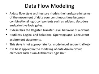
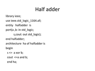
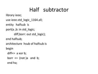
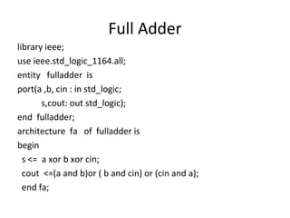
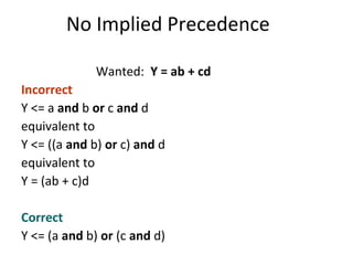
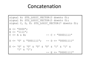
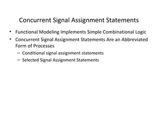
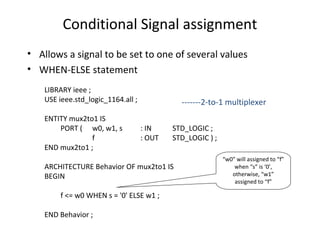
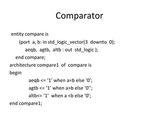
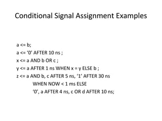
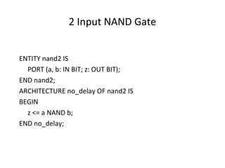
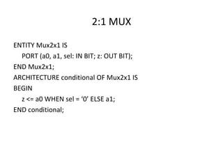
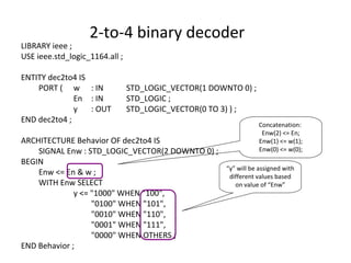
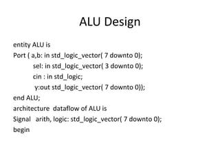
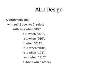
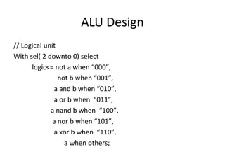
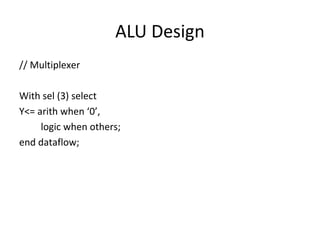
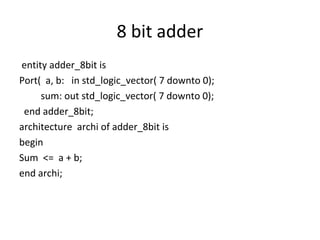
Data Flow Modeling in VHDL
Padmanaban K
Data Flow Modeling
• A data flow style architecture models the hardware in terms
of the movement of data over continuous time between
combinational logic components such as adders , decoders
and primitive logic gates.
• It describes the Register Transfer Level behavior of a circuit.
• It utilizes Logical and Relational Operators and Concurrent
assignment statements.
• This style is not appropriate for modeling of sequential logic.
• It is best applied in the modeling of data driven circuit
elements such as an Arithmetic Logic Unit.
Half adder
library ieee;
use ieee.std_logic_1164.all;
entity halfadder is
port(a ,b: in std_logic;
s,cout: out std_logic);
end halfadder;
architecture ha of halfadder is
begin
s <= a xor b;
cout <=a and b;
end ha;
Half subtractor
library ieee;
use ieee.std_logic_1164.all;
entity halfsub is
port(a ,b: in std_logic;
diff,borr: out std_logic);
end halfsub;
architecture hsub of halfsub is
begin
diff<= a xor b;
borr <= (not )a and b;
end ha;
Full Adder
library ieee;
use ieee.std_logic_1164.all;
entity fulladder is
port(a ,b, cin : in std_logic;
s,cout: out std_logic);
end fulladder;
architecture fa of fulladder is
begin
s <= a xor b xor cin;
cout <=(a and b)or ( b and cin) or (cin and a);
end fa;
Rules For Logical Operators
Logic Operators
• Logic operators
• Logic operators precedence
and or nand nor xor not xnor
not
and or nand nor xor xnor
Highest
Lowest
Wanted: Y = ab + cd
Incorrect
Y <= a and b or c and d
equivalent to
Y <= ((a and b) or c) and d
equivalent to
Y = (ab + c)d
Correct
Y <= (a and b) or (c and d)
No Implied Precedence
Concatenation
signal A: STD_LOGIC_VECTOR(3 downto 0);
signal B: STD_LOGIC_VECTOR(3 downto 0);
signal C, D, E: STD_LOGIC_VECTOR(7 downto 0);
A <= ”0000”;
B <= ”1111”;
C <= A & B; -- C = ”00001111”
D <= ‘0’ & ”0001111”; -- D <= ”00001111”
E <= ‘0’ & ‘0’ & ‘0’ & ‘0’ & ‘1’ & ‘1’ &
‘1’ & ‘1’;
-- E <= ”00001111”
Concurrent Signal Assignment Statements
• Functional Modeling Implements Simple Combinational Logic
• Concurrent Signal Assignment Statements Are an Abbreviated
Form of Processes
– Conditional signal assignment statements
– Selected Signal Assignment Statements
Conditional Signal assignment
• Allows a signal to be set to one of several values
• WHEN-ELSE statement
-------2-to-1 multiplexer
LIBRARY ieee ;
USE ieee.std_logic_1164.all ;
ENTITY mux2to1 IS
PORT ( w0, w1, s : IN STD_LOGIC ;
f : OUT STD_LOGIC ) ;
END mux2to1 ;
ARCHITECTURE Behavior OF mux2to1 IS
BEGIN
f <= w0 WHEN s = '0' ELSE w1 ;
END Behavior ;
“w0” will assigned to “f”
when “s” is ‘0’,
otherwise, “w1”
assigned to “f”
Comparator
entity compare is
(port a, b: in std_logic_vector(3 downto 0);
aeqb, agtb, altb : out std_logic );
end compare;
architecture compare1 of compare is
begin
aeqb <= ‘1’ when a=b else ‘0’;
agtb <= ‘1’ when a>b else ‘0’’;
altb<= ‘1’ when a <b else ‘0’;
end compare1;
Conditional Signal Assignment Examples
a <= b;
a <= ‘0’ AFTER 10 ns ;
x <= a AND b OR c ;
y <= a AFTER 1 ns WHEN x = y ELSE b ;
z <= a AND b, c AFTER 5 ns, ‘1’ AFTER 30 ns
WHEN NOW < 1 ms ELSE
‘0’, a AFTER 4 ns, c OR d AFTER 10 ns;
2 Input NAND Gate
ENTITY nand2 IS
PORT (a, b: IN BIT; z: OUT BIT);
END nand2;
ARCHITECTURE no_delay OF nand2 IS
BEGIN
z <= a NAND b;
END no_delay;
2:1 MUX
ENTITY Mux2x1 IS
PORT (a0, a1, sel: IN BIT; z: OUT BIT);
END Mux2x1;
ARCHITECTURE conditional OF Mux2x1 IS
BEGIN
z <= a0 WHEN sel = ‘0’ ELSE a1;
END conditional;
Selected signal assignment
• Allows a signal to be assigned one of several values, based on
a selection criterion
• Examples: can be used to implement multiplexer
• WITH-SELECT statement
Selected Signal Assignment
WITH expression SELECT
target <= selected_waveforms ;
selected_waveforms ::=
{ waveform WHEN choices, }
waveform WHEN choices
choices ::= choice { | choice }
choice ::= expression | range | simple_name | OTHERS
VHDL Models For A Multiplexer
F <= (not A and not B and I0) or
(not A and B and I1) or
(A and not B and I2) or
(A and B and I3);
MUX model using a conditional signal assignment
statement :
F <= I0 when Sel = 0
else I1 when Sel = 1
else I2 when Sel = 2
else I3;
MUX
I0
I1
I2
I3
A B
F
4-to-1 Multiplexer
LIBRARY ieee ;
USE ieee.std_logic_1164.all ;
ENTITY mux4to1 IS
PORT ( w0, w1, w2, w3 : IN STD_LOGIC ;
s : IN STD_LOGIC_VECTOR(1 DOWNTO 0) ;
f : OUT STD_LOGIC ) ;
END mux4to1 ;
ARCHITECTURE Behavior OF mux4to1 IS
BEGIN
WITH s SELECT
f <= w0 WHEN "00",
w1 WHEN "01",
w2 WHEN "10",
w3 WHEN OTHERS ;
END Behavior ;
Selection based on value
of signal “s”. For example,
when “s” is “00”, value of
“w0” will assigned to “f”
2-to-4 binary decoder
LIBRARY ieee ;
USE ieee.std_logic_1164.all ;
ENTITY dec2to4 IS
PORT ( w : IN STD_LOGIC_VECTOR(1 DOWNTO 0) ;
En : IN STD_LOGIC ;
y : OUT STD_LOGIC_VECTOR(0 TO 3) ) ;
END dec2to4 ;
ARCHITECTURE Behavior OF dec2to4 IS
SIGNAL Enw : STD_LOGIC_VECTOR(2 DOWNTO 0) ;
BEGIN
Enw <= En & w ;
WITH Enw SELECT
y <= "1000" WHEN "100",
"0100" WHEN "101",
"0010" WHEN "110",
"0001" WHEN "111",
"0000" WHEN OTHERS ;
END Behavior ;
“y” will be assigned with
different values based
on value of “Enw”
Concatenation:
Enw(2) <= En;
Enw(1) <= w(1);
Enw(0) <= w(0);
ALU Design
entity ALU is
Port ( a,b: in std_logic_vector( 7 downto 0);
sel: in std_logic_vector( 3 downto 0);
cin : in std_logic;
y:out std_logic_vector( 7 downto 0));
end ALU;
architecture dataflow of ALU is
Signal arith, logic: std_logic_vector( 7 downto 0);
begin
ALU Design
// Arithmetic Unit
with sel( 2 downto 0) select
arith <= a when “000”,
a+1 when “001”,
a-1 when “010”,
b when “011”,
b+1 when “100”,
b-1 when “101”,
a+b when “110”,
a+b+cin when others;
ALU Design
// Logical unit
With sel( 2 downto 0) select
logic<= not a when “000”,
not b when “001”,
a and b when “010”,
a or b when “011”,
a nand b when “100”,
a nor b when “101”,
a xor b when “110”,
a when others;
ALU Design
// Multiplexer
With sel (3) select
Y<= arith when ‘0’,
logic when others;
end dataflow;
8 bit adder
entity adder_8bit is
Port( a, b: in std_logic_vector( 7 downto 0);
sum: out std_logic_vector( 7 downto 0);
end adder_8bit;
architecture archi of adder_8bit is
begin
Sum <= a + b;
end archi;

Data Flow Modeling

  • 1.
    Data Flow Modelingin VHDL Padmanaban K
  • 2.
    Data Flow Modeling •A data flow style architecture models the hardware in terms of the movement of data over continuous time between combinational logic components such as adders , decoders and primitive logic gates. • It describes the Register Transfer Level behavior of a circuit. • It utilizes Logical and Relational Operators and Concurrent assignment statements. • This style is not appropriate for modeling of sequential logic. • It is best applied in the modeling of data driven circuit elements such as an Arithmetic Logic Unit.
  • 3.
    Half adder library ieee; useieee.std_logic_1164.all; entity halfadder is port(a ,b: in std_logic; s,cout: out std_logic); end halfadder; architecture ha of halfadder is begin s <= a xor b; cout <=a and b; end ha;
  • 4.
    Half subtractor library ieee; useieee.std_logic_1164.all; entity halfsub is port(a ,b: in std_logic; diff,borr: out std_logic); end halfsub; architecture hsub of halfsub is begin diff<= a xor b; borr <= (not )a and b; end ha;
  • 5.
    Full Adder library ieee; useieee.std_logic_1164.all; entity fulladder is port(a ,b, cin : in std_logic; s,cout: out std_logic); end fulladder; architecture fa of fulladder is begin s <= a xor b xor cin; cout <=(a and b)or ( b and cin) or (cin and a); end fa;
  • 6.
  • 7.
    Logic Operators • Logicoperators • Logic operators precedence and or nand nor xor not xnor not and or nand nor xor xnor Highest Lowest
  • 8.
    Wanted: Y =ab + cd Incorrect Y <= a and b or c and d equivalent to Y <= ((a and b) or c) and d equivalent to Y = (ab + c)d Correct Y <= (a and b) or (c and d) No Implied Precedence
  • 9.
    Concatenation signal A: STD_LOGIC_VECTOR(3downto 0); signal B: STD_LOGIC_VECTOR(3 downto 0); signal C, D, E: STD_LOGIC_VECTOR(7 downto 0); A <= ”0000”; B <= ”1111”; C <= A & B; -- C = ”00001111” D <= ‘0’ & ”0001111”; -- D <= ”00001111” E <= ‘0’ & ‘0’ & ‘0’ & ‘0’ & ‘1’ & ‘1’ & ‘1’ & ‘1’; -- E <= ”00001111”
  • 10.
    Concurrent Signal AssignmentStatements • Functional Modeling Implements Simple Combinational Logic • Concurrent Signal Assignment Statements Are an Abbreviated Form of Processes – Conditional signal assignment statements – Selected Signal Assignment Statements
  • 11.
    Conditional Signal assignment •Allows a signal to be set to one of several values • WHEN-ELSE statement -------2-to-1 multiplexer LIBRARY ieee ; USE ieee.std_logic_1164.all ; ENTITY mux2to1 IS PORT ( w0, w1, s : IN STD_LOGIC ; f : OUT STD_LOGIC ) ; END mux2to1 ; ARCHITECTURE Behavior OF mux2to1 IS BEGIN f <= w0 WHEN s = '0' ELSE w1 ; END Behavior ; “w0” will assigned to “f” when “s” is ‘0’, otherwise, “w1” assigned to “f”
  • 12.
    Comparator entity compare is (porta, b: in std_logic_vector(3 downto 0); aeqb, agtb, altb : out std_logic ); end compare; architecture compare1 of compare is begin aeqb <= ‘1’ when a=b else ‘0’; agtb <= ‘1’ when a>b else ‘0’’; altb<= ‘1’ when a <b else ‘0’; end compare1;
  • 13.
    Conditional Signal AssignmentExamples a <= b; a <= ‘0’ AFTER 10 ns ; x <= a AND b OR c ; y <= a AFTER 1 ns WHEN x = y ELSE b ; z <= a AND b, c AFTER 5 ns, ‘1’ AFTER 30 ns WHEN NOW < 1 ms ELSE ‘0’, a AFTER 4 ns, c OR d AFTER 10 ns;
  • 14.
    2 Input NANDGate ENTITY nand2 IS PORT (a, b: IN BIT; z: OUT BIT); END nand2; ARCHITECTURE no_delay OF nand2 IS BEGIN z <= a NAND b; END no_delay;
  • 15.
    2:1 MUX ENTITY Mux2x1IS PORT (a0, a1, sel: IN BIT; z: OUT BIT); END Mux2x1; ARCHITECTURE conditional OF Mux2x1 IS BEGIN z <= a0 WHEN sel = ‘0’ ELSE a1; END conditional;
  • 16.
    Selected signal assignment •Allows a signal to be assigned one of several values, based on a selection criterion • Examples: can be used to implement multiplexer • WITH-SELECT statement
  • 17.
    Selected Signal Assignment WITHexpression SELECT target <= selected_waveforms ; selected_waveforms ::= { waveform WHEN choices, } waveform WHEN choices choices ::= choice { | choice } choice ::= expression | range | simple_name | OTHERS
  • 18.
    VHDL Models ForA Multiplexer F <= (not A and not B and I0) or (not A and B and I1) or (A and not B and I2) or (A and B and I3); MUX model using a conditional signal assignment statement : F <= I0 when Sel = 0 else I1 when Sel = 1 else I2 when Sel = 2 else I3; MUX I0 I1 I2 I3 A B F
  • 19.
    4-to-1 Multiplexer LIBRARY ieee; USE ieee.std_logic_1164.all ; ENTITY mux4to1 IS PORT ( w0, w1, w2, w3 : IN STD_LOGIC ; s : IN STD_LOGIC_VECTOR(1 DOWNTO 0) ; f : OUT STD_LOGIC ) ; END mux4to1 ; ARCHITECTURE Behavior OF mux4to1 IS BEGIN WITH s SELECT f <= w0 WHEN "00", w1 WHEN "01", w2 WHEN "10", w3 WHEN OTHERS ; END Behavior ; Selection based on value of signal “s”. For example, when “s” is “00”, value of “w0” will assigned to “f”
  • 20.
    2-to-4 binary decoder LIBRARYieee ; USE ieee.std_logic_1164.all ; ENTITY dec2to4 IS PORT ( w : IN STD_LOGIC_VECTOR(1 DOWNTO 0) ; En : IN STD_LOGIC ; y : OUT STD_LOGIC_VECTOR(0 TO 3) ) ; END dec2to4 ; ARCHITECTURE Behavior OF dec2to4 IS SIGNAL Enw : STD_LOGIC_VECTOR(2 DOWNTO 0) ; BEGIN Enw <= En & w ; WITH Enw SELECT y <= "1000" WHEN "100", "0100" WHEN "101", "0010" WHEN "110", "0001" WHEN "111", "0000" WHEN OTHERS ; END Behavior ; “y” will be assigned with different values based on value of “Enw” Concatenation: Enw(2) <= En; Enw(1) <= w(1); Enw(0) <= w(0);
  • 21.
    ALU Design entity ALUis Port ( a,b: in std_logic_vector( 7 downto 0); sel: in std_logic_vector( 3 downto 0); cin : in std_logic; y:out std_logic_vector( 7 downto 0)); end ALU; architecture dataflow of ALU is Signal arith, logic: std_logic_vector( 7 downto 0); begin
  • 22.
    ALU Design // ArithmeticUnit with sel( 2 downto 0) select arith <= a when “000”, a+1 when “001”, a-1 when “010”, b when “011”, b+1 when “100”, b-1 when “101”, a+b when “110”, a+b+cin when others;
  • 23.
    ALU Design // Logicalunit With sel( 2 downto 0) select logic<= not a when “000”, not b when “001”, a and b when “010”, a or b when “011”, a nand b when “100”, a nor b when “101”, a xor b when “110”, a when others;
  • 24.
    ALU Design // Multiplexer Withsel (3) select Y<= arith when ‘0’, logic when others; end dataflow;
  • 25.
    8 bit adder entityadder_8bit is Port( a, b: in std_logic_vector( 7 downto 0); sum: out std_logic_vector( 7 downto 0); end adder_8bit; architecture archi of adder_8bit is begin Sum <= a + b; end archi;

Editor's Notes

  • #8 No order precedents
  • #9 No order precedents