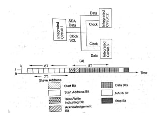
Serial Communication Protocols-
Inter-Integrated circuits(I2C)
By,
Mrs.S.Revathi
• The I2C bus is a popular bus.
• The l2C was originally developed at Philips
Semiconductors.
• There are three I2C bus standards:
 Industrial 100 kbps l2C,
100 kbps SM I2C and
400 kbps l2C.
• I2C Bus has two lines that carry the signals one
line is for the clock and one is for bidirectional
data.
• I2C bus protocol has specific fields.
• Each field has specific number of bits and
sequences and time intervals between them.
• The master is a source device, one that transmits
the clock pulses for synchronization at the
destination.
• The master has a processing element, which
functions as a bus controller or microcontroller
with I2C bus interface circuit.
• Each 12C device has an address using which the
data transfers take place.
• A master can address 127 other slaves at an
instance.
• Each slave can also optionally have I2C bus
controller or a processing element.
• Any number of masters can be connected on the
bus. However, at an instance, the master is one
which initiates a data transfer on SDA (serial data)
line and which transmits the SCL (serial clock)
pulses.
• First field of 1 bit- Start bit similar to UART
Second field of 7 bits- Address field, which defines slave
address, which is being sent the data frame (of many bytes) by
the master using SDA and SCL
Third field of 1 control bit- Control field 1, which defines
whether a read or write cycle is in progress.
Fourth field of 1 control bit- Control field 2, which defines
whether the present data is an acknowledgment (from slave).
• Fifth field of 8 bits- Data field for I2c device data byte.
• Sixth field of 1 bit- NACK (negative acknowledgement) field
in data frame, if active then acknowledgment after a transfer is
not needed from the slave; else, acknowledgement is expected
from the slave.
• Seventh field of 1 bit- Stop bit like in an UART
• A disadvantage of I2C bus is the time taken by the
algorithm executing at master hardware.
• The algorithm analyses the bits through I2C in case the
slave hardware does not provide for the hardware that
supports it.
• Some ICs support the protocol and some do not. Also,
there are open collector drivers at the master.
• Therefore, a pull-up resistance of 2.2 K on each line is
essential.
• I2C is a serial bus for interconnecting ICs.
• It has the start and stop bits as in the UART.
• It has seven fields: Start, 7-bits address, bit for defining
a read or write, byte for defining acknowledging, data
byte, NACK and End.
THANK YOU

Inter intergrated circuits-communication protocol

  • 1.
    Serial Communication Protocols- Inter-Integratedcircuits(I2C) By, Mrs.S.Revathi
  • 2.
    • The I2Cbus is a popular bus. • The l2C was originally developed at Philips Semiconductors. • There are three I2C bus standards:  Industrial 100 kbps l2C, 100 kbps SM I2C and 400 kbps l2C.
  • 3.
    • I2C Bushas two lines that carry the signals one line is for the clock and one is for bidirectional data. • I2C bus protocol has specific fields. • Each field has specific number of bits and sequences and time intervals between them. • The master is a source device, one that transmits the clock pulses for synchronization at the destination.
  • 4.
    • The masterhas a processing element, which functions as a bus controller or microcontroller with I2C bus interface circuit. • Each 12C device has an address using which the data transfers take place. • A master can address 127 other slaves at an instance. • Each slave can also optionally have I2C bus controller or a processing element. • Any number of masters can be connected on the bus. However, at an instance, the master is one which initiates a data transfer on SDA (serial data) line and which transmits the SCL (serial clock) pulses.
  • 6.
    • First fieldof 1 bit- Start bit similar to UART Second field of 7 bits- Address field, which defines slave address, which is being sent the data frame (of many bytes) by the master using SDA and SCL Third field of 1 control bit- Control field 1, which defines whether a read or write cycle is in progress. Fourth field of 1 control bit- Control field 2, which defines whether the present data is an acknowledgment (from slave). • Fifth field of 8 bits- Data field for I2c device data byte. • Sixth field of 1 bit- NACK (negative acknowledgement) field in data frame, if active then acknowledgment after a transfer is not needed from the slave; else, acknowledgement is expected from the slave. • Seventh field of 1 bit- Stop bit like in an UART
  • 7.
    • A disadvantageof I2C bus is the time taken by the algorithm executing at master hardware. • The algorithm analyses the bits through I2C in case the slave hardware does not provide for the hardware that supports it. • Some ICs support the protocol and some do not. Also, there are open collector drivers at the master. • Therefore, a pull-up resistance of 2.2 K on each line is essential. • I2C is a serial bus for interconnecting ICs. • It has the start and stop bits as in the UART. • It has seven fields: Start, 7-bits address, bit for defining a read or write, byte for defining acknowledging, data byte, NACK and End.
  • 8.