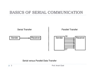
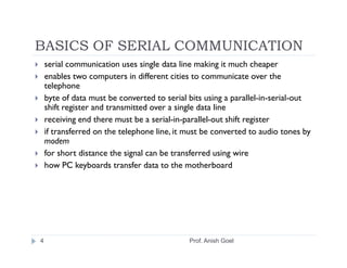
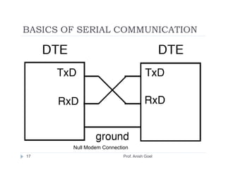
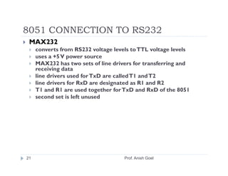
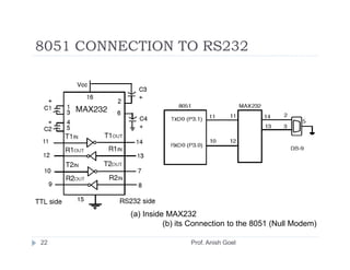
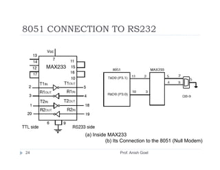
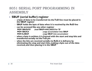
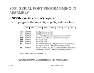
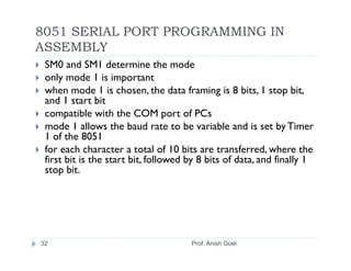
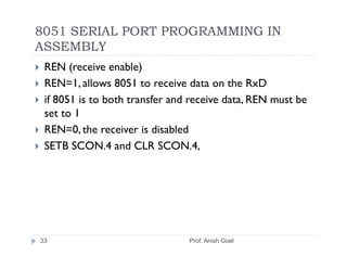
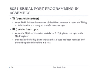
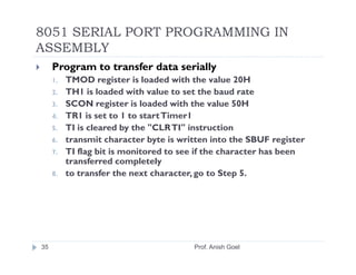
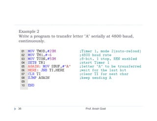
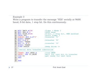
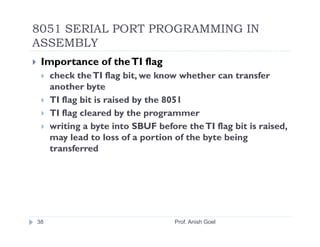
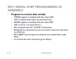
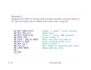
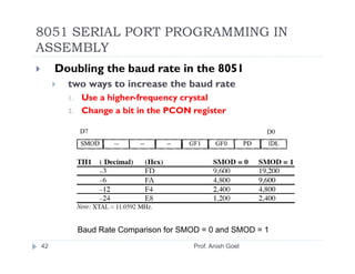
8051 SERIAL PORT
PROGRAMMING IN ASSEMBLY
                Prof. Anish Goel
OBJECTIVES
    Contrast and compare serial versus parallel communication
    List the advantages of serial communication over parallel
    Explain serial communication protocol
    Contrast synchronous versus asynchronous communication
    Contrast half-versus full-duplex transmission
    Explain the process of data framing
    Describe data transfer rate and bps rate
    Define the RS232 standard
    Explain the use of the MAX232 and MAX233 chips


2                                          Prof. Anish Goel
BASICS OF SERIAL COMMUNICATION


     Serial versus Parallel Data Transfer

3                                   Prof. Anish Goel
BASICS OF SERIAL COMMUNICATION
    serial communication uses single data line making it much cheaper
    enables two computers in different cities to communicate over the
    telephone
    byte of data must be converted to serial bits using a parallel-in-serial-out
    shift register and transmitted over a single data line
    receiving end there must be a serial-in-parallel-out shift register
    if transferred on the telephone line, it must be converted to audio tones by
    modem
    for short distance the signal can be transferred using wire
    how PC keyboards transfer data to the motherboard


4                                            Prof. Anish Goel
BASICS OF SERIAL COMMUNICATION
    2 methods, asynchronous and synchronous
    synchronous method transfers a block of data (characters) at a
    time
    asynchronous method transfers a single byte at a time
    Uses special IC chips called UART (universal asynchronous
    receiver-transmitter) and USART (universal
    synchronous­asynchronous receiver-transmitter)
    8051 chip has a built-in UART


5                                     Prof. Anish Goel
BASICS OF SERIAL COMMUNICATION


    Simplex, Half-, and Full-Duplex Transfers

6                                   Prof. Anish Goel
BASICS OF SERIAL COMMUNICATION
    Half- and full-duplex transmission
      if the data can be transmitted and received, it is a duplex transmission
      simplex transmissions the computer only sends data
      duplex transmissions can be half or full duplex
      depends on whether or not the data transfer can be simultaneous
      If one way at a time, it is half duplex
      If can go both ways at the same time, it is full duplex
      full duplex requires two wire conductors for the data lines (in addition
      to the signal ground)


7                                            Prof. Anish Goel
BASICS OF SERIAL COMMUNICATION
    Asynchronous serial communication and data
    framing
     data coming in 0s and 1s
     to make sense of the data sender and receiver agree
     on a set of rules
     Protocol
       how the data is packed
       how many bits/character
       when the data begins and ends


8                                      Prof. Anish Goel
BASICS OF SERIAL COMMUNICATION
    Start and stop bits
     asynchronous method, each character is placed
     between start and stop bits
     called framing
     start bit is always one bit
     stop bit can be one or two bits
     start bit is always a 0 (low)
     stop bit(s) is 1 (high)
     LSB is sent out first


9                               Prof. Anish Goel
BASICS OF SERIAL COMMUNICATION


        Framing ASCII “A” (41H)


10                           Prof. Anish Goel
BASICS OF SERIAL COMMUNICATION
 in modern PCs one stop bit is standard
 when transferring a text file of ASCII characters
 using 1 stop bit there is total of 10 bits for each
 character
 8 bits for the ASCII code (1 parity bit), 1 bit each
 for the start and stop bits
 for each 8-bit character there are an extra 2 bits,
 which gives 20% overhead


11                            Prof. Anish Goel
BASICS OF SERIAL COMMUNICATION
 Data transfer rate
     rate of data transfer bps (bits per second)
     widely used terminology for bps is baud rate
     baud and bps rates are not necessarily equal
     baud rate is defined as the number of signal changes
     per second


12                               Prof. Anish Goel
BASICS OF SERIAL COMMUNICATION
 RS232 standards
     most widely used serial I/O interfacing standard
     input and output voltage levels are not TTL compatible
     1 bit is represented by -3 to -25 V
     0 bit is +3 to +25 V
     -3 to +3 is undefined
     to connect RS232 to a microcontroller system must use
     voltage converters such as MAX232 to convert the TTL logic
     levels to the RS232 voltage levels, and vice versa
     MAX232 IC chips are commonly referred to as line drivers


13                                  Prof. Anish Goel
BASICS OF SERIAL COMMUNICATION


                 Figure 10–4     RS232 Connector DB-25


           RS232 Pins (DB-25)


14                     Prof. Anish Goel
BASICS OF SERIAL COMMUNICATION


                             DB-9 9-Pin Connector


     IBM PC DB-9 Signals

15                         Prof. Anish Goel
BASICS OF SERIAL COMMUNICATION
 Data communication classification
     DTE (data terminal equipment)
     DCE (data communication equipment)
     DTE - terminals and computers that send and receive data
     DCE - communication equipment responsible for transferring
     the data
     simplest connection between a PC and microcontroller
     requires a minimum of three pins,TxD, RxD, and ground


16                                  Prof. Anish Goel
BASICS OF SERIAL COMMUNICATION


        Null Modem Connection
17                         Prof. Anish Goel
BASICS OF SERIAL COMMUNICATION
 Examining RS232 hand­shaking signals
     many of the pins of the RS-232 connector are used for
     handshaking signals
     they are not supported by the 8051 UART chip


18                               Prof. Anish Goel
BASICS OF SERIAL COMMUNICATION
 PC/compatible COM ports
     PC/compatible computers (Pentium) microprocessors
     normally have two COM ports
     both ports have RS232-type connectors
     COM ports are designated as COM 1 and COM 2
     (replaced by USB ports)
     can connect the 8051 serial port to the COM 2 port


19                             Prof. Anish Goel
8051 CONNECTION TO RS232
 RxD and TxD pins in the 8051
     8051 has two pins used for transferring and receiving data
     serially
     TxD and RxD are part of the port 3 group
     pin 11 (P3.1) is assigned to TxD
     pin 10 (P3.0) is designated as RxD
     these pins are TTL compatible
     require a line driver to make them RS232 compatible
     driver is the MAX232 chip


20                                    Prof. Anish Goel
8051 CONNECTION TO RS232
 MAX232
     converts from RS232 voltage levels to TTL voltage levels
     uses a +5 V power source
     MAX232 has two sets of line drivers for transferring and
     receiving data
     line drivers used for TxD are called T1 and T2
     line drivers for RxD are designated as R1 and R2
     T1 and R1 are used together for TxD and RxD of the 8051
     second set is left unused


21                                   Prof. Anish Goel
8051 CONNECTION TO RS232


          (a) Inside MAX232
                    (b) its Connection to the 8051 (Null Modem)

22                         Prof. Anish Goel
8051 CONNECTION TO RS232
 MAX233
     MAX233 performs the same job as the MAX232
     eliminates the need for capacitors
     much more expensive than the MAX232


23                            Prof. Anish Goel
8051 CONNECTION TO RS232


           (a) Inside MAX233
                     (b) Its Connection to the 8051 (Null Modem)

24                        Prof. Anish Goel
8051 SERIAL PORT PROGRAMMING IN
ASSEMBLY
 Baud rate in the 8051
     serial communications of the 8051 with the COM port
     of the PC
     must make sure that the baud rate of the 8051 system
     matches the baud rate of the PC's COM port
     can use Windows HyperTerminal program


25                              Prof. Anish Goel
8051 SERIAL PORT PROGRAMMING IN
ASSEMBLY


          PC Baud Rates

26                        Prof. Anish Goel
8051 SERIAL PORT PROGRAMMING IN
ASSEMBLY
 Baud rate in the 8051
     baud rate in the 8051 is programmable
     done with the help of Timer 1
     relationship between the crystal frequency and the baud rate in the 8051
     8051 divides the crystal frequency by 12 to get the machine cycle frequency
     XTAL = 11.0592 MHz, the machine cycle frequency is 921.6 kHz
     8051's UART divides the machine cycle frequency of 921.6 kHz by 32 once
     more before it is used by Timer 1 to set the baud rate
     921.6 kHz divided by 32 gives 28,800 Hz
     Timer 1 must be programmed in mode 2, that is 8-bit, auto-reload


27                                            Prof. Anish Goel
8051 SERIAL PORT PROGRAMMING IN
ASSEMBLY


     Timer 1 TH1 Register Values for Various Baud Rates
28                                      Prof. Anish Goel
Example 1
With XTAL = 11.0592 MHz, find the TH1 value needed to have the
following baud rates. (a) 9600(b) 2400        (c) 1200


      machine cycle frequency
      = 11.0592 MHz / 12 = 921.6 kHz
      Timer 1 frequency provided by 8051 UART
      = 921.6 kHz / 32 = 28,800 Hz

(a) 28,800 / 3 = 9600 where -3        = FD (hex)
(b) 28,800 / 12 = 2400 where -12      = F4 (hex)
(c) 28,800 / 24 = 1200 where -24      = E8 (hex)


 29                                  Prof. Anish Goel
8051 SERIAL PORT PROGRAMMING IN
ASSEMBLY
 SBUF (serial buffer) register
     a byte of data to be transferred via the TxD line must be placed in
     the SBUF register
     SBUF holds the byte of data when it is received by the RxD line
     can be accessed like any other register
     MOV SBUF,#'D'     ;load SBUF=44H, ASCII for 'D‘
     MOV SBUF,A                 ;copy accumulator into SBUF
     MOV A,SBUF                 ;copy SBUF into accumulator
     when a byte is written, it is framed with the start and stop bits and
     transferred serially via the TxD pin
     when the bits are received serially via RxD, it is deframe by
     eliminating the stop and start bits, making a byte out of the data
     received, and then placing it in the SBUF


30                                      Prof. Anish Goel
8051 SERIAL PORT PROGRAMMING IN
ASSEMBLY
 SCON (serial control) register
     to program the start bit, stop bit, and data bits


        SCON Serial Port Control Register (Bit-Addressable)

31                                       Prof. Anish Goel
8051 SERIAL PORT PROGRAMMING IN
ASSEMBLY
 SM0 and SM1 determine the mode
 only mode 1 is important
 when mode 1 is chosen, the data framing is 8 bits, 1 stop bit,
 and 1 start bit
 compatible with the COM port of PCs
 mode 1 allows the baud rate to be variable and is set by Timer
 1 of the 8051
 for each character a total of 10 bits are transferred, where the
 first bit is the start bit, followed by 8 bits of data, and finally 1
 stop bit.


32                                    Prof. Anish Goel
8051 SERIAL PORT PROGRAMMING IN
ASSEMBLY
 REN (receive enable)
 REN=1, allows 8051 to receive data on the RxD
 if 8051 is to both transfer and receive data, REN must be
 set to 1
 REN=0, the receiver is disabled
 SETB SCON.4 and CLR SCON.4,


33                              Prof. Anish Goel
8051 SERIAL PORT PROGRAMMING IN
ASSEMBLY
 TI (transmit interrupt)
     when 8051 finishes the transfer of the 8-bit character, it raises the TI flag
     to indicate that it is ready to transfer another byte
 RI (receive interrupt)
     when the 8051 receives data serially via RxD, it places the byte in the
     SBUF register
     then raises the RI flag bit to indicate that a byte has been received and
     should be picked up before it is lost


34                                           Prof. Anish Goel
8051 SERIAL PORT PROGRAMMING IN
ASSEMBLY
     Program to transfer data serially
     1.   TMOD register is loaded with the value 20H
     2.   TH1 is loaded with value to set the baud rate
     3.   SCON register is loaded with the value 50H
     4.   TR1 is set to 1 to start Timer1
     5.   TI is cleared by the "CLR TI" instruction
     6.   transmit character byte is written into the SBUF register
     7.   TI flag bit is monitored to see if the character has been
          transferred completely
     8.   to transfer the next character, go to Step 5.


35                                      Prof. Anish Goel
Example 2
Write a program to transfer letter "A" serially at 4800 baud,
continuously.


36                                 Prof. Anish Goel
Example 3
 Write a program to transfer the message "YES" serially at 9600
 baud, 8-bit data, 1 stop bit. Do this continuously.


37                                   Prof. Anish Goel
8051 SERIAL PORT PROGRAMMING IN
ASSEMBLY
 Importance of the TI flag
     check the TI flag bit, we know whether can transfer
     another byte
     TI flag bit is raised by the 8051
     TI flag cleared by the programmer
     writing a byte into SBUF before the TI flag bit is raised,
     may lead to loss of a portion of the byte being
     transferred


38                                 Prof. Anish Goel
8051 SERIAL PORT PROGRAMMING IN
ASSEMBLY
     Program to receive data serially
     1.   TMOD register is loaded with the value 20H
     2.   TH1 is loaded with value set the baud rate
     3.   SCON register is loaded with the value 50H
     4.   TR1 is set to 1 to start Timer 1
     5.   RI is cleared with the "CLR RI" instruction
     6.   RI flag bit is monitored to see if an entire character has been
          received yet
     7.   RI=1 SBUF has the byte, its contents are moved into a safe
          place
     8.   to receive the next character, go to Step 5


39                                        Prof. Anish Goel
Example 4
 Program the 8051 to receive bytes of data serially, and put them in
 P1. Set the baud rate at 4800, 8-bit data, and 1 stop bit.


40                                    Prof. Anish Goel
8051 SERIAL PORT PROGRAMMING IN
ASSEMBLY
     Importance of the RI flag bit
     1.   it receives the start bit, next bit is the first bit of the
          character
     2.   when the last bit is received, a byte is formed and placed in
          SBUF
     3.   when stop bit is received, makes RI = 1
     4.   when RI=1, received byte is in the SBUF register, copy SBUF
          contents to a safe place
     5.   after the SBUF contents are copied the RI flag bit must be
          cleared to 0


41                                       Prof. Anish Goel
8051 SERIAL PORT PROGRAMMING IN
ASSEMBLY
     Doubling the baud rate in the 8051
       two ways to increase the baud rate
       1.   Use a higher-frequency crystal
       2.   Change a bit in the PCON register


            Baud Rate Comparison for SMOD = 0 and SMOD = 1
42                                     Prof. Anish Goel
8051 SERIAL PORT PROGRAMMING IN
ASSEMBLY
 Interrupt-based data transfer
     it is a waste of the microcontroller's time to poll the TI
     and RI flags
     to avoid wasting time, use interrupts instead of polling


43                                 Prof. Anish Goel

Serial1

  • 1.
    8051 SERIAL PORT PROGRAMMINGIN ASSEMBLY Prof. Anish Goel
  • 2.
    OBJECTIVES Contrast and compare serial versus parallel communication List the advantages of serial communication over parallel Explain serial communication protocol Contrast synchronous versus asynchronous communication Contrast half-versus full-duplex transmission Explain the process of data framing Describe data transfer rate and bps rate Define the RS232 standard Explain the use of the MAX232 and MAX233 chips 2 Prof. Anish Goel
  • 3.
    BASICS OF SERIALCOMMUNICATION Serial versus Parallel Data Transfer 3 Prof. Anish Goel
  • 4.
    BASICS OF SERIALCOMMUNICATION serial communication uses single data line making it much cheaper enables two computers in different cities to communicate over the telephone byte of data must be converted to serial bits using a parallel-in-serial-out shift register and transmitted over a single data line receiving end there must be a serial-in-parallel-out shift register if transferred on the telephone line, it must be converted to audio tones by modem for short distance the signal can be transferred using wire how PC keyboards transfer data to the motherboard 4 Prof. Anish Goel
  • 5.
    BASICS OF SERIALCOMMUNICATION 2 methods, asynchronous and synchronous synchronous method transfers a block of data (characters) at a time asynchronous method transfers a single byte at a time Uses special IC chips called UART (universal asynchronous receiver-transmitter) and USART (universal synchronous­asynchronous receiver-transmitter) 8051 chip has a built-in UART 5 Prof. Anish Goel
  • 6.
    BASICS OF SERIALCOMMUNICATION Simplex, Half-, and Full-Duplex Transfers 6 Prof. Anish Goel
  • 7.
    BASICS OF SERIALCOMMUNICATION Half- and full-duplex transmission if the data can be transmitted and received, it is a duplex transmission simplex transmissions the computer only sends data duplex transmissions can be half or full duplex depends on whether or not the data transfer can be simultaneous If one way at a time, it is half duplex If can go both ways at the same time, it is full duplex full duplex requires two wire conductors for the data lines (in addition to the signal ground) 7 Prof. Anish Goel
  • 8.
    BASICS OF SERIALCOMMUNICATION Asynchronous serial communication and data framing data coming in 0s and 1s to make sense of the data sender and receiver agree on a set of rules Protocol how the data is packed how many bits/character when the data begins and ends 8 Prof. Anish Goel
  • 9.
    BASICS OF SERIALCOMMUNICATION Start and stop bits asynchronous method, each character is placed between start and stop bits called framing start bit is always one bit stop bit can be one or two bits start bit is always a 0 (low) stop bit(s) is 1 (high) LSB is sent out first 9 Prof. Anish Goel
  • 10.
    BASICS OF SERIALCOMMUNICATION Framing ASCII “A” (41H) 10 Prof. Anish Goel
  • 11.
    BASICS OF SERIALCOMMUNICATION in modern PCs one stop bit is standard when transferring a text file of ASCII characters using 1 stop bit there is total of 10 bits for each character 8 bits for the ASCII code (1 parity bit), 1 bit each for the start and stop bits for each 8-bit character there are an extra 2 bits, which gives 20% overhead 11 Prof. Anish Goel
  • 12.
    BASICS OF SERIALCOMMUNICATION Data transfer rate rate of data transfer bps (bits per second) widely used terminology for bps is baud rate baud and bps rates are not necessarily equal baud rate is defined as the number of signal changes per second 12 Prof. Anish Goel
  • 13.
    BASICS OF SERIALCOMMUNICATION RS232 standards most widely used serial I/O interfacing standard input and output voltage levels are not TTL compatible 1 bit is represented by -3 to -25 V 0 bit is +3 to +25 V -3 to +3 is undefined to connect RS232 to a microcontroller system must use voltage converters such as MAX232 to convert the TTL logic levels to the RS232 voltage levels, and vice versa MAX232 IC chips are commonly referred to as line drivers 13 Prof. Anish Goel
  • 14.
    BASICS OF SERIALCOMMUNICATION Figure 10–4 RS232 Connector DB-25 RS232 Pins (DB-25) 14 Prof. Anish Goel
  • 15.
    BASICS OF SERIALCOMMUNICATION DB-9 9-Pin Connector IBM PC DB-9 Signals 15 Prof. Anish Goel
  • 16.
    BASICS OF SERIALCOMMUNICATION Data communication classification DTE (data terminal equipment) DCE (data communication equipment) DTE - terminals and computers that send and receive data DCE - communication equipment responsible for transferring the data simplest connection between a PC and microcontroller requires a minimum of three pins,TxD, RxD, and ground 16 Prof. Anish Goel
  • 17.
    BASICS OF SERIALCOMMUNICATION Null Modem Connection 17 Prof. Anish Goel
  • 18.
    BASICS OF SERIALCOMMUNICATION Examining RS232 hand­shaking signals many of the pins of the RS-232 connector are used for handshaking signals they are not supported by the 8051 UART chip 18 Prof. Anish Goel
  • 19.
    BASICS OF SERIALCOMMUNICATION PC/compatible COM ports PC/compatible computers (Pentium) microprocessors normally have two COM ports both ports have RS232-type connectors COM ports are designated as COM 1 and COM 2 (replaced by USB ports) can connect the 8051 serial port to the COM 2 port 19 Prof. Anish Goel
  • 20.
    8051 CONNECTION TORS232 RxD and TxD pins in the 8051 8051 has two pins used for transferring and receiving data serially TxD and RxD are part of the port 3 group pin 11 (P3.1) is assigned to TxD pin 10 (P3.0) is designated as RxD these pins are TTL compatible require a line driver to make them RS232 compatible driver is the MAX232 chip 20 Prof. Anish Goel
  • 21.
    8051 CONNECTION TORS232 MAX232 converts from RS232 voltage levels to TTL voltage levels uses a +5 V power source MAX232 has two sets of line drivers for transferring and receiving data line drivers used for TxD are called T1 and T2 line drivers for RxD are designated as R1 and R2 T1 and R1 are used together for TxD and RxD of the 8051 second set is left unused 21 Prof. Anish Goel
  • 22.
    8051 CONNECTION TORS232 (a) Inside MAX232 (b) its Connection to the 8051 (Null Modem) 22 Prof. Anish Goel
  • 23.
    8051 CONNECTION TORS232 MAX233 MAX233 performs the same job as the MAX232 eliminates the need for capacitors much more expensive than the MAX232 23 Prof. Anish Goel
  • 24.
    8051 CONNECTION TORS232 (a) Inside MAX233 (b) Its Connection to the 8051 (Null Modem) 24 Prof. Anish Goel
  • 25.
    8051 SERIAL PORTPROGRAMMING IN ASSEMBLY Baud rate in the 8051 serial communications of the 8051 with the COM port of the PC must make sure that the baud rate of the 8051 system matches the baud rate of the PC's COM port can use Windows HyperTerminal program 25 Prof. Anish Goel
  • 26.
    8051 SERIAL PORTPROGRAMMING IN ASSEMBLY PC Baud Rates 26 Prof. Anish Goel
  • 27.
    8051 SERIAL PORTPROGRAMMING IN ASSEMBLY Baud rate in the 8051 baud rate in the 8051 is programmable done with the help of Timer 1 relationship between the crystal frequency and the baud rate in the 8051 8051 divides the crystal frequency by 12 to get the machine cycle frequency XTAL = 11.0592 MHz, the machine cycle frequency is 921.6 kHz 8051's UART divides the machine cycle frequency of 921.6 kHz by 32 once more before it is used by Timer 1 to set the baud rate 921.6 kHz divided by 32 gives 28,800 Hz Timer 1 must be programmed in mode 2, that is 8-bit, auto-reload 27 Prof. Anish Goel
  • 28.
    8051 SERIAL PORTPROGRAMMING IN ASSEMBLY Timer 1 TH1 Register Values for Various Baud Rates 28 Prof. Anish Goel
  • 29.
    Example 1 With XTAL= 11.0592 MHz, find the TH1 value needed to have the following baud rates. (a) 9600(b) 2400 (c) 1200 machine cycle frequency = 11.0592 MHz / 12 = 921.6 kHz Timer 1 frequency provided by 8051 UART = 921.6 kHz / 32 = 28,800 Hz (a) 28,800 / 3 = 9600 where -3 = FD (hex) (b) 28,800 / 12 = 2400 where -12 = F4 (hex) (c) 28,800 / 24 = 1200 where -24 = E8 (hex) 29 Prof. Anish Goel
  • 30.
    8051 SERIAL PORTPROGRAMMING IN ASSEMBLY SBUF (serial buffer) register a byte of data to be transferred via the TxD line must be placed in the SBUF register SBUF holds the byte of data when it is received by the RxD line can be accessed like any other register MOV SBUF,#'D' ;load SBUF=44H, ASCII for 'D‘ MOV SBUF,A ;copy accumulator into SBUF MOV A,SBUF ;copy SBUF into accumulator when a byte is written, it is framed with the start and stop bits and transferred serially via the TxD pin when the bits are received serially via RxD, it is deframe by eliminating the stop and start bits, making a byte out of the data received, and then placing it in the SBUF 30 Prof. Anish Goel
  • 31.
    8051 SERIAL PORTPROGRAMMING IN ASSEMBLY SCON (serial control) register to program the start bit, stop bit, and data bits SCON Serial Port Control Register (Bit-Addressable) 31 Prof. Anish Goel
  • 32.
    8051 SERIAL PORTPROGRAMMING IN ASSEMBLY SM0 and SM1 determine the mode only mode 1 is important when mode 1 is chosen, the data framing is 8 bits, 1 stop bit, and 1 start bit compatible with the COM port of PCs mode 1 allows the baud rate to be variable and is set by Timer 1 of the 8051 for each character a total of 10 bits are transferred, where the first bit is the start bit, followed by 8 bits of data, and finally 1 stop bit. 32 Prof. Anish Goel
  • 33.
    8051 SERIAL PORTPROGRAMMING IN ASSEMBLY REN (receive enable) REN=1, allows 8051 to receive data on the RxD if 8051 is to both transfer and receive data, REN must be set to 1 REN=0, the receiver is disabled SETB SCON.4 and CLR SCON.4, 33 Prof. Anish Goel
  • 34.
    8051 SERIAL PORTPROGRAMMING IN ASSEMBLY TI (transmit interrupt) when 8051 finishes the transfer of the 8-bit character, it raises the TI flag to indicate that it is ready to transfer another byte RI (receive interrupt) when the 8051 receives data serially via RxD, it places the byte in the SBUF register then raises the RI flag bit to indicate that a byte has been received and should be picked up before it is lost 34 Prof. Anish Goel
  • 35.
    8051 SERIAL PORTPROGRAMMING IN ASSEMBLY Program to transfer data serially 1. TMOD register is loaded with the value 20H 2. TH1 is loaded with value to set the baud rate 3. SCON register is loaded with the value 50H 4. TR1 is set to 1 to start Timer1 5. TI is cleared by the "CLR TI" instruction 6. transmit character byte is written into the SBUF register 7. TI flag bit is monitored to see if the character has been transferred completely 8. to transfer the next character, go to Step 5. 35 Prof. Anish Goel
  • 36.
    Example 2 Write aprogram to transfer letter "A" serially at 4800 baud, continuously. 36 Prof. Anish Goel
  • 37.
    Example 3 Writea program to transfer the message "YES" serially at 9600 baud, 8-bit data, 1 stop bit. Do this continuously. 37 Prof. Anish Goel
  • 38.
    8051 SERIAL PORTPROGRAMMING IN ASSEMBLY Importance of the TI flag check the TI flag bit, we know whether can transfer another byte TI flag bit is raised by the 8051 TI flag cleared by the programmer writing a byte into SBUF before the TI flag bit is raised, may lead to loss of a portion of the byte being transferred 38 Prof. Anish Goel
  • 39.
    8051 SERIAL PORTPROGRAMMING IN ASSEMBLY Program to receive data serially 1. TMOD register is loaded with the value 20H 2. TH1 is loaded with value set the baud rate 3. SCON register is loaded with the value 50H 4. TR1 is set to 1 to start Timer 1 5. RI is cleared with the "CLR RI" instruction 6. RI flag bit is monitored to see if an entire character has been received yet 7. RI=1 SBUF has the byte, its contents are moved into a safe place 8. to receive the next character, go to Step 5 39 Prof. Anish Goel
  • 40.
    Example 4 Programthe 8051 to receive bytes of data serially, and put them in P1. Set the baud rate at 4800, 8-bit data, and 1 stop bit. 40 Prof. Anish Goel
  • 41.
    8051 SERIAL PORTPROGRAMMING IN ASSEMBLY Importance of the RI flag bit 1. it receives the start bit, next bit is the first bit of the character 2. when the last bit is received, a byte is formed and placed in SBUF 3. when stop bit is received, makes RI = 1 4. when RI=1, received byte is in the SBUF register, copy SBUF contents to a safe place 5. after the SBUF contents are copied the RI flag bit must be cleared to 0 41 Prof. Anish Goel
  • 42.
    8051 SERIAL PORTPROGRAMMING IN ASSEMBLY Doubling the baud rate in the 8051 two ways to increase the baud rate 1. Use a higher-frequency crystal 2. Change a bit in the PCON register Baud Rate Comparison for SMOD = 0 and SMOD = 1 42 Prof. Anish Goel
  • 43.
    8051 SERIAL PORTPROGRAMMING IN ASSEMBLY Interrupt-based data transfer it is a waste of the microcontroller's time to poll the TI and RI flags to avoid wasting time, use interrupts instead of polling 43 Prof. Anish Goel