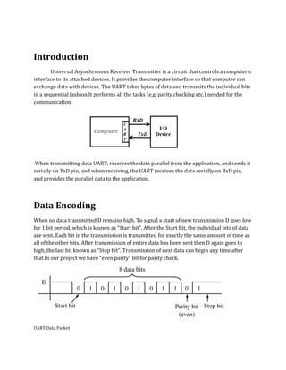
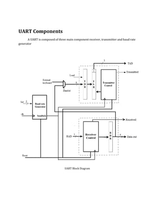
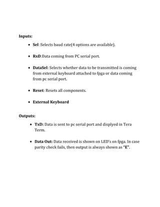
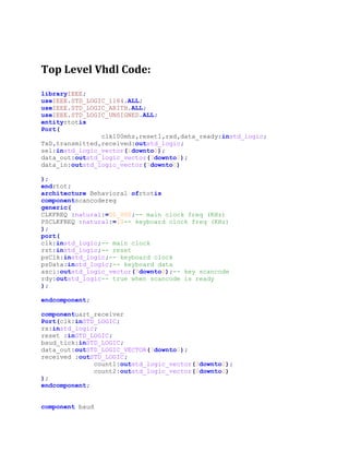
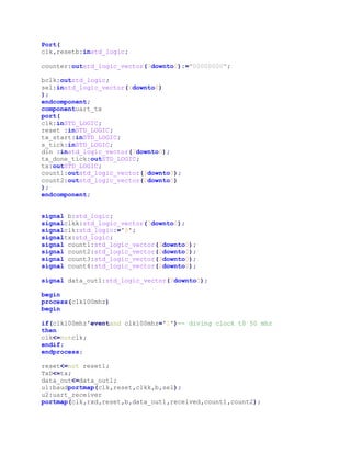
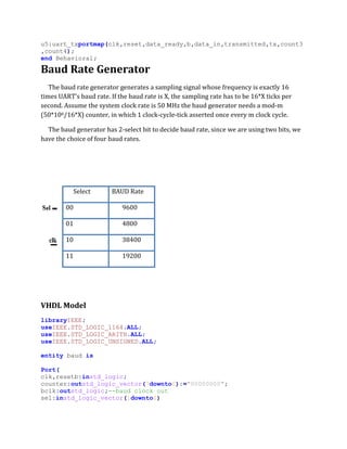
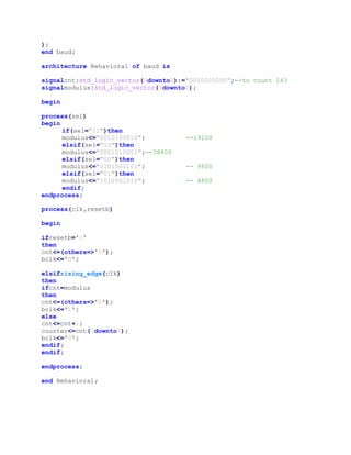
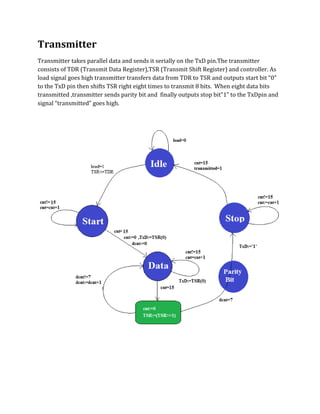
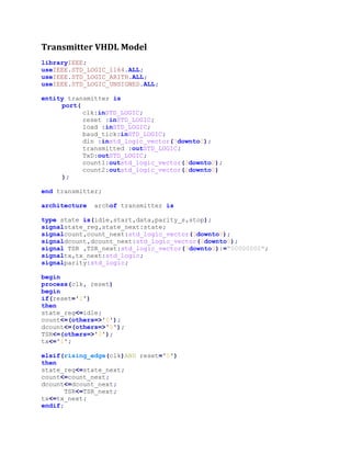
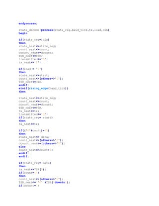
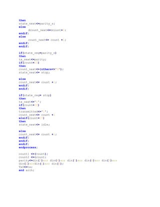
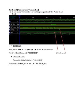
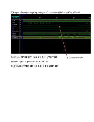
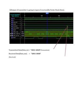
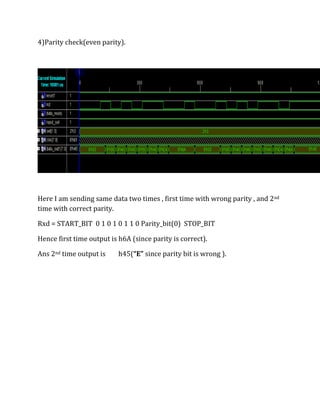
SlideShare a Scribd company logo
Universal Asynchronous Receiver   Transmitter<br />     Submitted By:-<br />             HariomMeena(2009cs10190)<br />                                   Rohan Sharma(2009cs10211)                             <br />Introduction<br />Universal Asynchronous Receiver Transmitter is a circuit that controls a computer’s interface to its attached devices.  It provides the computer interface so that computer can exchange data with devices. The UART takes bytes of data and transmits the individual bits in a sequential fashion. It performs all the tasks (e.g. parity checking etc.) needed for the communication.<br />  <br /> When transmitting data UART, receives the data parallel from the application, and sends it serially on TxD pin, and when receiving, the UART receives the data serially on RxD pin, and provides the parallel data to the application.<br />Data Encoding<br />            When no data transmitted D remains high. To signal   a start of new transmission D goes low for 1 bit period, which is known as “Start bit”. After the Start Bit, the individual bits of data are sent. Each bit in the transmission is transmitted for exactly the same amount of time as all of the other bits. After transmission of entire data has been sent then D again goes to high, the last bit known as “Stop bit”. Transmission of next data can begin any time after that. In our project we have  “even parity” bit for parity check.<br />                                                                    <br />                                                              UART Data Packet<br />UART Components   <br />A UART is composed of three main component receiver, transmitter and baud rate generator <br /> <br /> <br />41148005229225TransmitterControl00TransmitterControlUART Block Diagram<br />Inputs:<br />,[object Object]
RxD: Data coming from PC serial port.
DataSel: Selects whether data to be transmitted is coming    from external keyboard attached to fpga or data coming from pc serial port.
Reset: Resets all components.
External KeyboardOutputs: <br />,[object Object]
Data Out: Data received is shown on LED’s on fpga. In case parity check fails, then output is always shown as “E”.   <br />   <br />Top Level Vhdl Code:<br />library IEEE; <br />use IEEE.STD_LOGIC_1164.ALL; <br />use IEEE.STD_LOGIC_ARITH.ALL; <br />use IEEE.STD_LOGIC_UNSIGNED.ALL; <br />entity rtot is <br />    Port (<br />                clk100mhz,reset1,rxd,data_ready:in std_logic;   <br />                TxD,transmitted,received:out std_logic;<br />                sel:in std_logic_vector(1 downto 0);<br />                data_out:out std_logic_vector(7 downto 0);<br />                data_in:out std_logic_vector(7 downto 0)<br />            <br />            );         <br />end rtot; <br />architecture Behavioral of rtot is <br />component scancodereg <br />generic(<br />CLKFREQ : natural := 50_000; -- main clock freq (KHz)<br />PSCLKFREQ : natural := 10 -- keyboard clock freq (KHz)<br />);<br />port(<br />clk : in std_logic; -- main clock<br />rst : in std_logic; -- reset<br />psClk : in std_logic; -- keyboard clock<br />psData : in std_logic; -- keyboard data<br />asci : out std_logic_vector(7 downto 0); -- key scancode<br />rdy : out std_logic -- true when scancode is ready<br />);<br />end component;<br />component uart_receiver <br />    Port ( clk : in  STD_LOGIC;<br />           rx:in std_logic;<br />              reset : in  STD_LOGIC;<br />           baud_tick : in  STD_LOGIC;<br />           data_out : out  STD_LOGIC_VECTOR(7 downto 0);<br />           received : out  STD_LOGIC;<br />              count1:out  std_logic_vector(3 downto 0);<br />              count2:out  std_logic_vector(2 downto 0)<br />              );<br />end component;<br /> <br />component baud <br />    Port (<br />                clk,resetb:in std_logic; <br />                <br />                counter: out std_logic_vector(7 downto 0):=quot;
00000000quot;
;<br />                <br />                bclk:out std_logic;<br />                sel:in std_logic_vector(1 downto 0)<br />            ); <br />end component; <br />component uart_tx <br />port (<br />clk : in  STD_LOGIC;<br />reset : in  STD_LOGIC;<br />tx_start : in STD_LOGIC;<br />s_tick : in STD_LOGIC;<br />din :  in std_logic_vector ( 7   downto   0); <br />tx_done_tick : out  STD_LOGIC;<br />tx :   out  STD_LOGIC;<br />count1:out  std_logic_vector(3 downto 0);<br />count2:out  std_logic_vector(2 downto 0)<br />); <br />end component;<br /> <br />signal b:std_logic; <br />signal clkk:std_logic_vector(7 downto 0);<br />signal clk: std_logic:='0';<br />signal tx:std_logic;<br />signal count1:std_logic_vector(3 downto 0);<br />signal count2:std_logic_vector(2 downto 0);<br />signal count3:std_logic_vector(3 downto 0);<br />signal count4:std_logic_vector(2 downto 0);<br />signal data_out1:std_logic_vector(7 downto 0);<br />begin <br />process(clk100mhz)<br />begin<br />if(clk100mhz'event and clk100mhz='1')   -- diving clock t0 50 mhz<br />then <br />clk<=not clk;<br />end if;<br />end process;<br />reset<= not reset1;<br />TxD<=tx;<br />data_out<=data_out1;<br />u1:baud port map(clk,reset,clkk,b,sel);            <br />u2:uart_receiver port map(clk,rxd,reset,b,data_out1,received,count1,count2); <br />u5: uart_tx port map (clk,reset,data_ready,b,data_in,transmitted,tx,count3,count4);<br />end Behavioral;<br />Baud Rate Generator <br />     The baud rate generator generates a sampling signal whose frequency is exactly 16 times UART’s baud rate. If the baud rate is X, the sampling rate has to be 16*X ticks per second. Assume the system clock rate is 50 MHz the baud generator needs a mod-m (50*106/16*X) counter, in which 1 clock-cycle-tick asserted once every m clock cycle.<br />     The baud generator has 2-select bit to decide baud rate, since we are using two bits, we have the choice of four baud rates. <br />  <br />     Select BAUD Rate       00       9600       01       4800       10       38400       11       19200<br />                                                                                               <br />    <br />VHDL Model<br />library IEEE; <br />use IEEE.STD_LOGIC_1164.ALL; <br />use IEEE.STD_LOGIC_ARITH.ALL; <br />use IEEE.STD_LOGIC_UNSIGNED.ALL; <br />entity baud is <br />      Port (<br />                clk,resetb:in std_logic;                 <br />                counter: out std_logic_vector(7 downto 0):=quot;
00000000quot;
;                <br />                bclk:out std_logic      ;       --baud clock out<br />                sel:in std_logic_vector(1 downto 0)<br />            ); <br />end baud; <br />architecture Behavioral of baud is <br />signal cnt:std_logic_vector(9 downto 0):=quot;
0000000000quot;
; --to count 163<br />signal modulus:std_logic_vector(9 downto 0);<br />begin <br />    <br />    process(sel)<br />     begin<br />    if(sel=quot;
11quot;
) then<br />     modulus<=quot;
0010100010quot;
; --19200<br />   elsif(sel=quot;
10quot;
) then<br />     modulus<=quot;
0001010001quot;
;          --38400<br />   elsif(sel=quot;
00quot;
) then<br />     modulus<=quot;
0101000101quot;
;   -- 9600<br />   elsif(sel=quot;
01quot;
) then<br />     modulus<=quot;
1010001010quot;
;   -- 4800    <br />   end if;<br />    end process;    <br />    process(clk,resetb) <br />        begin <br />            if resetb='1' <br />               then <br />                   cnt<=(others=>'0'); <br />                   bclk<='0';                            <br />            <br />            elsif rising_edge(clk)<br />               then <br />                  if cnt=modulus <br />                    then <br />                      cnt<=(others=>'0'); <br />                      bclk<='1';                         <br />                  else <br />                      cnt<=cnt+1;                             <br />                      counter<=cnt(7 downto 0);                          <br />                      bclk<='0';         <br />                  end if; <br />            end if; <br />    end process; <br />end Behavioral; <br />TEST BENCH (BAUD CLOCK)<br />,[object Object],Here select bits are “11” ,hence baud rate is 19200.<br />Time period of baud clock = 1/(19200* 16)=3.25 *10-6. s<br />,[object Object],Now  select bits are “00” ,hence baud rate =9600<br />Time period =1/(9600*16) =6.5 * 10-6 s<br />Receiver <br />      Receiver takes data serially in RxD pin, and provides the parallel to the Data out pin. UART receiver consists of RDR (Received Data Reg.) and controller. When the UART detects start bit receiver reads and shifts 8 data bits serially into a temporary register. When 8 data bits has been received and parity check passes then after stop bit has been received controller transfers data from temporary register to RDR and received signal goes high. If parity check fails then , output of receiver is always shown as “E”.<br />  <br />                                                                           Receiver state machine<br />Receiver VHDL Model<br />library IEEE;<br />use IEEE.STD_LOGIC_1164.ALL;<br />use IEEE.STD_LOGIC_ARITH.ALL;<br />use IEEE.STD_LOGIC_UNSIGNED.ALL;<br />entity uart_receiver is<br />    Port ( clk : in  STD_LOGIC;<br />           rx:in std_logic;<br />              reset : in  STD_LOGIC;<br />           baud_tick : in  STD_LOGIC;<br />           data_out : out  STD_LOGIC_VECTOR(7 downto 0);<br />           received : out  STD_LOGIC;<br />              count1:out  std_logic_vector(3 downto 0);<br />              count2:out  std_logic_vector(2 downto 0)<br />              );<br />end uart_receiver;<br />architecture Behavioral of uart_receiver is<br />type state is (idle,startbit,databits,paritybit,stopbit);<br />signal state_reg,next_state_reg: state; <br />signal counter,next_count:std_logic_vector(3 downto 0);<br />signal data_count,data_next_count:std_logic_vector(2 downto 0);<br />signal rec,next_rec:std_logic_vector(7 downto 0):=quot;
00000000quot;
;<br />signal parity:std_logic;<br />begin<br />process(clk, reset)<br />  begin<br />   <br />    if(reset='1')<br />     then <br />     state_reg<=idle;<br />      counter<=(others=>'0');<br />     data_count<=(others=>'0');<br />      <br />      <br />    elsif(rising_edge(clk) AND reset='0')<br />     then   <br />     state_reg<=next_state_reg;<br />     counter<=next_count;                      <br />     data_count<=data_next_count;              <br />     rec<=next_rec; <br />    <br />   end if;<br />end process;<br />state_decode:process (state_reg,rx,counter,baud_tick)<br />   begin<br />       <br />      if(state_reg=idle) then<br />                 <br />                    next_state_reg <= state_reg; <br />                    data_next_count<=data_count;      <br />                  received<='0';<br />                    next_count<=counter;<br />                    next_rec<=rec;<br />        <br />                    if (rx = '0') then<br />                    next_state_reg <= startbit;<br />                    next_count<=(others=>'0');<br />                    next_rec<=quot;
00000000quot;
;<br />                end if;<br />        <br />        elsif(rising_edge(baud_tick)) then<br />             <br />                  next_state_reg <= state_reg;  <br />               data_next_count<=data_count;                      <br />               received<='0';<br />                 next_count<=counter;<br />                 next_rec<=rec;<br />        <br />              <br />              if(state_reg= startbit)then<br />            <br />               if(('0'&counter)=7)<br />                    then<br />                    next_state_reg <=databits;<br />               next_count<=(others=>'0');<br />                   data_next_count<=(others=>'0');<br />                    else<br />                    next_count<=counter+1;<br />                    end if;<br />                    <br />                <br />                elsif(state_reg= databits)then<br />           <br />               if(('0'&counter)=15) then<br />                        next_count<=(others=>'0');<br />                         next_rec<=(rx & rec( 7 downto 1));<br />                        if(('0'&data_count)=7)then<br />                         next_state_reg<=paritybit;<br />                        else<br />                           data_next_count<=data_count+1;<br />                       end if;<br />                   else<br />                       next_count<=counter+1;<br />                    end if;<br />               <br />         elsif(state_reg= paritybit)then<br />           <br />               if(('0'&counter)=15) then<br />                        next_count<=(others=>'0');<br />                         next_state_reg<=stopbit;<br />                         <br />                         if(not(parity=rx)) then<br />                           next_rec<=quot;
01000101quot;
;<br />                         end if;<br />                            <br />                   else<br />                       next_count<=counter+1;<br />                    end if;<br />            <br />            elsif(state_reg= stopbit) then<br />               <br />               if(('0'&counter)=10)<br />                    then<br />                    received<='1';<br />                    next_count<=counter+1;<br />                    elsif(('0'&counter)=15) then<br />                    next_state_reg <=idle;<br />               <br />                    else<br />                    next_count<=counter+1;<br />                    end if;<br />                  end if;<br />            <br />            <br />        end if;<br />        end process;<br />            <br />parity<=rec(7) xor rec(6) xor rec(5) xor rec(4) xor rec(3) xor rec(2) xor rec(1) xor rec(0);<br />data_out<=rec;<br />count1<=counter;<br />count2<=data_count;<br />end Behavioral;<br />Transmitter<br />           Transmitter takes parallel data and sends it serially on the TxD pin. The transmitter consists of TDR (Transmit Data Register), TSR (Transmit Shift Register) and controller. As load signal goes high transmitter transfers data from TDR to TSR and outputs start bit “0” to the TxD pin then shifts TSR right eight times to transmit 8 bits.  When eight data bits transmitted ,transmitter sends parity bit and  finally outputs stop bit”1” to the TxD pin and signal “transmitted” goes high.<br />Transmitter VHDL Model<br />library IEEE;<br />use IEEE.STD_LOGIC_1164.ALL;<br />use IEEE.STD_LOGIC_ARITH.ALL;<br />use IEEE.STD_LOGIC_UNSIGNED.ALL;<br />entity transmitter is<br />port(<br />clk : in  STD_LOGIC;<br />reset : in  STD_LOGIC;<br />load : in STD_LOGIC;<br />baud_tick : in STD_LOGIC;<br />din :  in std_logic_vector ( 7   downto   0); <br />transmitted : out  STD_LOGIC;<br />TxD :   out  STD_LOGIC;<br />count1:out  std_logic_vector(3 downto 0);<br />count2:out  std_logic_vector(2 downto 0)<br />    ); <br />end transmitter;<br />architecture  arch of transmitter is <br />type state is (idle,start,data,parity_s,stop);<br />signal state_reg,state_next:state;<br />signal count,count_next:std_logic_vector (3 downto 0); <br />signal dcount , dcount_next : std_logic_vector ( 2 downto 0); <br />signal TSR , TSR_next : std_logic_vector (7 downto 0):=quot;
00000000quot;
; <br />signal tx ,tx_next : std_logic ;<br />signal parity:std_logic;<br />begin <br />process(clk, reset)<br />   begin<br />       if(reset='1')<br />      then <br />         state_reg<=idle;<br />         count<=(others=>'0');<br />         dcount<=(others=>'0');<br />         TSR<=(others=>'0');<br />         tx<='1';<br />      <br />    elsif(rising_edge(clk) AND reset='0')<br />      then   <br />         state_reg<=state_next;<br />         count<=count_next;<br />         dcount<=dcount_next;<br />         TSR<=TSR_next;<br />         tx<=tx_next;<br />   end if;<br />end process;<br />state_decode:process (state_reg,baud_tick,tx,load,din)<br />   begin<br />                 <br />      if(state_reg=idle) <br />         then                <br />            state_next<=state_reg;<br />            count_next<=count;<br />            dcount_next<=dcount;<br />            TSR_next<=TSR;<br />            transmitted<='0';<br />            tx_next<='1';<br />           if (load = '1') <br />               then<br />                 state_next<=start;<br />                 count_next<=(others=>'0');<br />                 TSR_next<=din;<br />           end if;       <br />      elsif(rising_edge(baud_tick)) <br />            then             <br />                <br />              state_next<=state_reg;<br />              count_next<=count;<br />              dcount_next<=dcount;<br />              TSR_next<=TSR;<br />              tx_next<=tx;<br />              transmitted<='0';                   <br />             if(state_reg= start) <br />                then<br />                  tx_next<=tx;<br />                 if(('0'&count)=15) <br />                    then<br />                      state_next <= data;<br />                      count_next<=(others=>'0');<br />                      dcount_next<=(others=>'0');<br />                 else<br />                      count_next<=count+1;<br />                 end if;<br />             end if;               <br />                <br />             if(state_reg = data)<br />                then<br />                  tx_next<=TSR(0);<br />                    if(count=15) <br />                       then<br />                         count_next <=(others=>'0');<br />                         TSR_next <= '0' & TSR(7 downto 1);<br />                         if(dcount=7)<br />                            then <br />                               state_next <= parity_s;<br />                         else <br />                       dcount_next<=dcount+1;<br />                         end if;<br />                   else<br />                  count_next <= count + 1;<br />                   end if;                <br />            end if;     <br />            if(state_reg= parity_s)<br />               then<br />                 tx_next<=parity;                             <br />                if(count=15) <br />                   then<br />                     count_next <= (others=>'0');                   <br />                     state_next <= stop;<br />                          <br />                else<br />                     count_next <= count + 1;<br />                end if;             <br />            end if;<br />         <br />            if(state_reg= stop) <br />               then<br />                 tx_next<='1';                                <br />                if(count=10) <br />                   then<br />                     transmitted<='1';<br />                     count_next <= count + 1  <br />                elsif(count=15) <br />                   then<br />                     state_next <= idle;<br />                       <br />                else<br />                     count_next <= count + 1;<br />                end if;             <br />            end if;<br />        end if;<br />    end process;<br /> <br />count1 <= (count);<br />count2 <= dcount;<br />parity<=din(7) xor din(6) xor din(5) xor din(4) xor din(3) xor din(2) xor din(1) xor din(0);<br />TxD <= tx;<br />end arch;<br />TestBench(Receiver and Transmitter):<br />,[object Object],529501515923590047527531741214<br />,[object Object],            RxD(rx)= START_BIT  1 0 1 0 1 0 1 1  STOP_BIT                       (Trasmitted)<br />           Received data(Data_out)= “11010101”             (Data Received) <br />,[object Object],Trnsmitted data(Data_in)= “10111010”<br />           TxD(txbit)=   START_BIT  0 1 0 1 1 1 0 1  STOP_BIT <br />396594411802142)Output of receiver is going to input of transmitter(No Parity Check Here).<br />RxD(rx) = START_BIT  1 0 1  0 1 0 1 1  STOP_BIT(Transmit signal)<br />Trasmit signal is given at around 600 us.<br />TxD(txbit)= START_BIT  1 0 1 0 1 0 1 1  STOP_BIT<br />3)Output of transmitter is going to input of receiver(No Parity Check Here).<br />581890914023930046464271631891<br />Transmitted Data(Data_in) =  “1011 1010”                            (Transmitted)<br />Received Data(Data_out)     =   “1011 1010”                                                     <br />                                                                                                                                  (Received)              <br />4)Parity check(even parity).<br />Here I am sending same data two times , first time with wrong parity , and 2nd time with correct parity.<br />Rxd = START_BIT  0 1 0 1 0 1 1 0 Parity_bit(0)  STOP_BIT<br />Hence first time output is h6A (since parity is correct).<br />Ans 2nd time output is        h45(“E” since parity bit is wrong ).<br />Work by each member:<br />,[object Object]
Rohan Sharma: Receiver, Baud Generator, External Keyboard drivers.
Uart
Uart
Uart
Uart
Uart
Uart
Uart
Uart
Uart
Uart
Uart
Uart
Uart
Uart
Uart

More Related Content

What's hot

Uart
UartUart
I2C introduction
I2C introductionI2C introduction
I2C introduction
SUNODH GARLAPATI
 
I2C Bus (Inter-Integrated Circuit)
I2C Bus (Inter-Integrated Circuit)I2C Bus (Inter-Integrated Circuit)
I2C Bus (Inter-Integrated Circuit)
Varun Mahajan
 
SPI Bus Protocol
SPI Bus ProtocolSPI Bus Protocol
SPI Bus Protocol
Sudhanshu Janwadkar
 
APB protocol v1.0
APB protocol v1.0APB protocol v1.0
APB protocol v1.0
Azad Mishra
 
3.programmable interrupt controller 8259
3.programmable interrupt controller 82593.programmable interrupt controller 8259
3.programmable interrupt controller 8259
MdFazleRabbi18
 
AMBA 2.0 PPT
AMBA 2.0 PPTAMBA 2.0 PPT
AMBA 2.0 PPT
Nirav Desai
 
USART
USARTUSART
I2C
I2CI2C
Serial Peripheral Interface
Serial Peripheral InterfaceSerial Peripheral Interface
Serial Peripheral Interface
Anurag Tomar
 
DMA presentation [By- Digvijay]
DMA presentation [By- Digvijay]DMA presentation [By- Digvijay]
DMA presentation [By- Digvijay]
Digvijay Singh Karakoti
 
I2C Protocol
I2C ProtocolI2C Protocol
I2C Protocol
Sudhanshu Janwadkar
 
Interfacing rs232
Interfacing rs232Interfacing rs232
Interfacing rs232
PRADEEP
 
UART(universal asynchronous receiver transmitter ) PPT
UART(universal asynchronous receiver transmitter ) PPTUART(universal asynchronous receiver transmitter ) PPT
UART(universal asynchronous receiver transmitter ) PPT
Sai_praneeth
 
The I2C Interface
The I2C InterfaceThe I2C Interface
The I2C Interface
Corrado Santoro
 
Delays in verilog
Delays in verilogDelays in verilog
Delays in verilog
JITU MISTRY
 
SystemVerilog Assertions verification with SVAUnit - DVCon US 2016 Tutorial
SystemVerilog Assertions verification with SVAUnit - DVCon US 2016 TutorialSystemVerilog Assertions verification with SVAUnit - DVCon US 2016 Tutorial
SystemVerilog Assertions verification with SVAUnit - DVCon US 2016 Tutorial
Amiq Consulting
 
8051 microcontroller
8051 microcontroller 8051 microcontroller
8051 microcontroller
Gaurav Verma
 
I/O port programming in 8051
I/O port programming in 8051I/O port programming in 8051
I/O port programming in 8051
ssuser3a47cb
 
Wishbone interface and bus cycles
Wishbone interface and bus cyclesWishbone interface and bus cycles
Wishbone interface and bus cycles
dennis gookyi
 

What's hot (20)

Uart
UartUart
Uart
 
I2C introduction
I2C introductionI2C introduction
I2C introduction
 
I2C Bus (Inter-Integrated Circuit)
I2C Bus (Inter-Integrated Circuit)I2C Bus (Inter-Integrated Circuit)
I2C Bus (Inter-Integrated Circuit)
 
SPI Bus Protocol
SPI Bus ProtocolSPI Bus Protocol
SPI Bus Protocol
 
APB protocol v1.0
APB protocol v1.0APB protocol v1.0
APB protocol v1.0
 
3.programmable interrupt controller 8259
3.programmable interrupt controller 82593.programmable interrupt controller 8259
3.programmable interrupt controller 8259
 
AMBA 2.0 PPT
AMBA 2.0 PPTAMBA 2.0 PPT
AMBA 2.0 PPT
 
USART
USARTUSART
USART
 
I2C
I2CI2C
I2C
 
Serial Peripheral Interface
Serial Peripheral InterfaceSerial Peripheral Interface
Serial Peripheral Interface
 
DMA presentation [By- Digvijay]
DMA presentation [By- Digvijay]DMA presentation [By- Digvijay]
DMA presentation [By- Digvijay]
 
I2C Protocol
I2C ProtocolI2C Protocol
I2C Protocol
 
Interfacing rs232
Interfacing rs232Interfacing rs232
Interfacing rs232
 
UART(universal asynchronous receiver transmitter ) PPT
UART(universal asynchronous receiver transmitter ) PPTUART(universal asynchronous receiver transmitter ) PPT
UART(universal asynchronous receiver transmitter ) PPT
 
The I2C Interface
The I2C InterfaceThe I2C Interface
The I2C Interface
 
Delays in verilog
Delays in verilogDelays in verilog
Delays in verilog
 
SystemVerilog Assertions verification with SVAUnit - DVCon US 2016 Tutorial
SystemVerilog Assertions verification with SVAUnit - DVCon US 2016 TutorialSystemVerilog Assertions verification with SVAUnit - DVCon US 2016 Tutorial
SystemVerilog Assertions verification with SVAUnit - DVCon US 2016 Tutorial
 
8051 microcontroller
8051 microcontroller 8051 microcontroller
8051 microcontroller
 
I/O port programming in 8051
I/O port programming in 8051I/O port programming in 8051
I/O port programming in 8051
 
Wishbone interface and bus cycles
Wishbone interface and bus cyclesWishbone interface and bus cycles
Wishbone interface and bus cycles
 

Viewers also liked

Lica 7th chapter slides
Lica 7th chapter slidesLica 7th chapter slides
Lica 7th chapter slides
SIVA NAGENDRA REDDY
 
Chapter 9
Chapter 9Chapter 9
Chapter 9
deval patel
 
Stack in microprocessor 8085(presantation)
Stack in microprocessor 8085(presantation)Stack in microprocessor 8085(presantation)
Stack in microprocessor 8085(presantation)
Safin Biswas
 
Interrupt
InterruptInterrupt
Interrupt
roshan_rawat
 
8051 serial communication-UART
8051 serial communication-UART8051 serial communication-UART
8051 serial communication-UART
Pantech ProLabs India Pvt Ltd
 
1206 Interrupts Of 8085
1206 Interrupts Of 80851206 Interrupts Of 8085
1206 Interrupts Of 8085
techbed
 
8259 a
8259 a8259 a
Interrupts of microprocessor 8085
Interrupts of microprocessor  8085Interrupts of microprocessor  8085
Interrupts of microprocessor 8085
mujeebkhanelectronic
 
8259 Programmable Interrupt Controller by vijay
8259 Programmable Interrupt Controller by vijay8259 Programmable Interrupt Controller by vijay
8259 Programmable Interrupt Controller by vijay
Vijay Kumar
 
8051 serial communication
8051 serial communication8051 serial communication
8051 serial communication
asteriskbimal
 
Stacks & subroutines 1
Stacks & subroutines 1Stacks & subroutines 1
Stacks & subroutines 1
deval patel
 

Viewers also liked (11)

Lica 7th chapter slides
Lica 7th chapter slidesLica 7th chapter slides
Lica 7th chapter slides
 
Chapter 9
Chapter 9Chapter 9
Chapter 9
 
Stack in microprocessor 8085(presantation)
Stack in microprocessor 8085(presantation)Stack in microprocessor 8085(presantation)
Stack in microprocessor 8085(presantation)
 
Interrupt
InterruptInterrupt
Interrupt
 
8051 serial communication-UART
8051 serial communication-UART8051 serial communication-UART
8051 serial communication-UART
 
1206 Interrupts Of 8085
1206 Interrupts Of 80851206 Interrupts Of 8085
1206 Interrupts Of 8085
 
8259 a
8259 a8259 a
8259 a
 
Interrupts of microprocessor 8085
Interrupts of microprocessor  8085Interrupts of microprocessor  8085
Interrupts of microprocessor 8085
 
8259 Programmable Interrupt Controller by vijay
8259 Programmable Interrupt Controller by vijay8259 Programmable Interrupt Controller by vijay
8259 Programmable Interrupt Controller by vijay
 
8051 serial communication
8051 serial communication8051 serial communication
8051 serial communication
 
Stacks & subroutines 1
Stacks & subroutines 1Stacks & subroutines 1
Stacks & subroutines 1
 

Similar to Uart

Fpga creating counter with internal clock
Fpga   creating counter with internal clockFpga   creating counter with internal clock
Fpga creating counter with internal clock
Politeknik Elektronika Negeri Surabaya
 
Uart
UartUart
Tdm to vo ip 2
Tdm to vo ip 2Tdm to vo ip 2
Tdm to vo ip 2
Abhiroop Mn
 
Fpga creating counter with external clock
Fpga   creating counter with external clockFpga   creating counter with external clock
Fpga creating counter with external clock
Politeknik Elektronika Negeri Surabaya
 
An Example MIPS
An Example  MIPSAn Example  MIPS
An Example MIPS
Sandra Long
 
vhdll.docx
vhdll.docxvhdll.docx
vhdll.docx
NguynTinDng35
 
Data Acquisition
Data AcquisitionData Acquisition
Data Acquisition
azhar557
 
Soc
SocSoc
Reporte vhdl9
Reporte vhdl9Reporte vhdl9
Reporte vhdl9
Miguel Angel Peña
 
W8_2: Inside the UoS Educational Processor
W8_2: Inside the UoS Educational ProcessorW8_2: Inside the UoS Educational Processor
W8_2: Inside the UoS Educational Processor
Daniel Roggen
 
Pipeline stalling in vhdl
Pipeline stalling in vhdlPipeline stalling in vhdl
Pipeline stalling in vhdl
Sai Malleswar
 
A Robust UART Architecture Based on Recursive Running Sum Filter for Better N...
A Robust UART Architecture Based on Recursive Running Sum Filter for Better N...A Robust UART Architecture Based on Recursive Running Sum Filter for Better N...
A Robust UART Architecture Based on Recursive Running Sum Filter for Better N...
Kevin Mathew
 
Direct analog
Direct analogDirect analog
Direct analog
srikanthsailu
 
Digital System Design Lab Report - VHDL ECE
Digital System Design Lab Report - VHDL ECEDigital System Design Lab Report - VHDL ECE
Digital System Design Lab Report - VHDL ECE
Ramesh Naik Bhukya
 
Em s7 plc
Em s7 plcEm s7 plc
Em s7 plc
chethanraj
 
VHDL Programs
VHDL ProgramsVHDL Programs
VHDL Programs
A B Shinde
 
Practical file
Practical filePractical file
Practical file
rajeevkr35
 
Intel Quark HSUART
Intel Quark HSUARTIntel Quark HSUART
Intel Quark HSUART
Shubham Kumar
 
Pythonによるカスタム可能な高位設計技術 (Design Solution Forum 2016@新横浜)
Pythonによるカスタム可能な高位設計技術 (Design Solution Forum 2016@新横浜)Pythonによるカスタム可能な高位設計技術 (Design Solution Forum 2016@新横浜)
Pythonによるカスタム可能な高位設計技術 (Design Solution Forum 2016@新横浜)
Shinya Takamaeda-Y
 
FPGA Tutorial - LCD Interface
FPGA Tutorial - LCD InterfaceFPGA Tutorial - LCD Interface
FPGA Tutorial - LCD Interface
Politeknik Elektronika Negeri Surabaya
 

Similar to Uart (20)

Fpga creating counter with internal clock
Fpga   creating counter with internal clockFpga   creating counter with internal clock
Fpga creating counter with internal clock
 
Uart
UartUart
Uart
 
Tdm to vo ip 2
Tdm to vo ip 2Tdm to vo ip 2
Tdm to vo ip 2
 
Fpga creating counter with external clock
Fpga   creating counter with external clockFpga   creating counter with external clock
Fpga creating counter with external clock
 
An Example MIPS
An Example  MIPSAn Example  MIPS
An Example MIPS
 
vhdll.docx
vhdll.docxvhdll.docx
vhdll.docx
 
Data Acquisition
Data AcquisitionData Acquisition
Data Acquisition
 
Soc
SocSoc
Soc
 
Reporte vhdl9
Reporte vhdl9Reporte vhdl9
Reporte vhdl9
 
W8_2: Inside the UoS Educational Processor
W8_2: Inside the UoS Educational ProcessorW8_2: Inside the UoS Educational Processor
W8_2: Inside the UoS Educational Processor
 
Pipeline stalling in vhdl
Pipeline stalling in vhdlPipeline stalling in vhdl
Pipeline stalling in vhdl
 
A Robust UART Architecture Based on Recursive Running Sum Filter for Better N...
A Robust UART Architecture Based on Recursive Running Sum Filter for Better N...A Robust UART Architecture Based on Recursive Running Sum Filter for Better N...
A Robust UART Architecture Based on Recursive Running Sum Filter for Better N...
 
Direct analog
Direct analogDirect analog
Direct analog
 
Digital System Design Lab Report - VHDL ECE
Digital System Design Lab Report - VHDL ECEDigital System Design Lab Report - VHDL ECE
Digital System Design Lab Report - VHDL ECE
 
Em s7 plc
Em s7 plcEm s7 plc
Em s7 plc
 
VHDL Programs
VHDL ProgramsVHDL Programs
VHDL Programs
 
Practical file
Practical filePractical file
Practical file
 
Intel Quark HSUART
Intel Quark HSUARTIntel Quark HSUART
Intel Quark HSUART
 
Pythonによるカスタム可能な高位設計技術 (Design Solution Forum 2016@新横浜)
Pythonによるカスタム可能な高位設計技術 (Design Solution Forum 2016@新横浜)Pythonによるカスタム可能な高位設計技術 (Design Solution Forum 2016@新横浜)
Pythonによるカスタム可能な高位設計技術 (Design Solution Forum 2016@新横浜)
 
FPGA Tutorial - LCD Interface
FPGA Tutorial - LCD InterfaceFPGA Tutorial - LCD Interface
FPGA Tutorial - LCD Interface
 

Uart