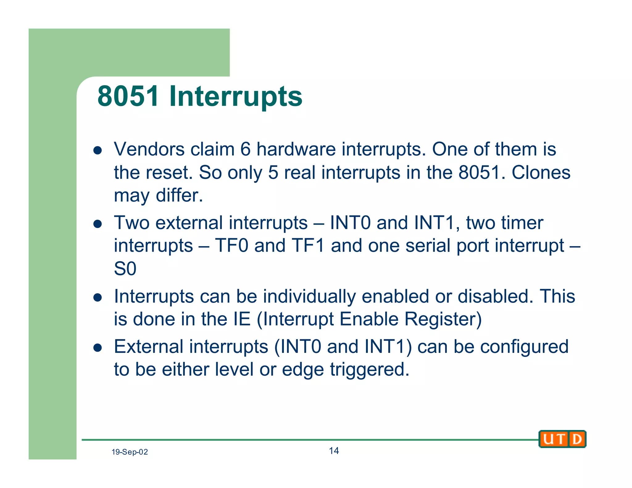
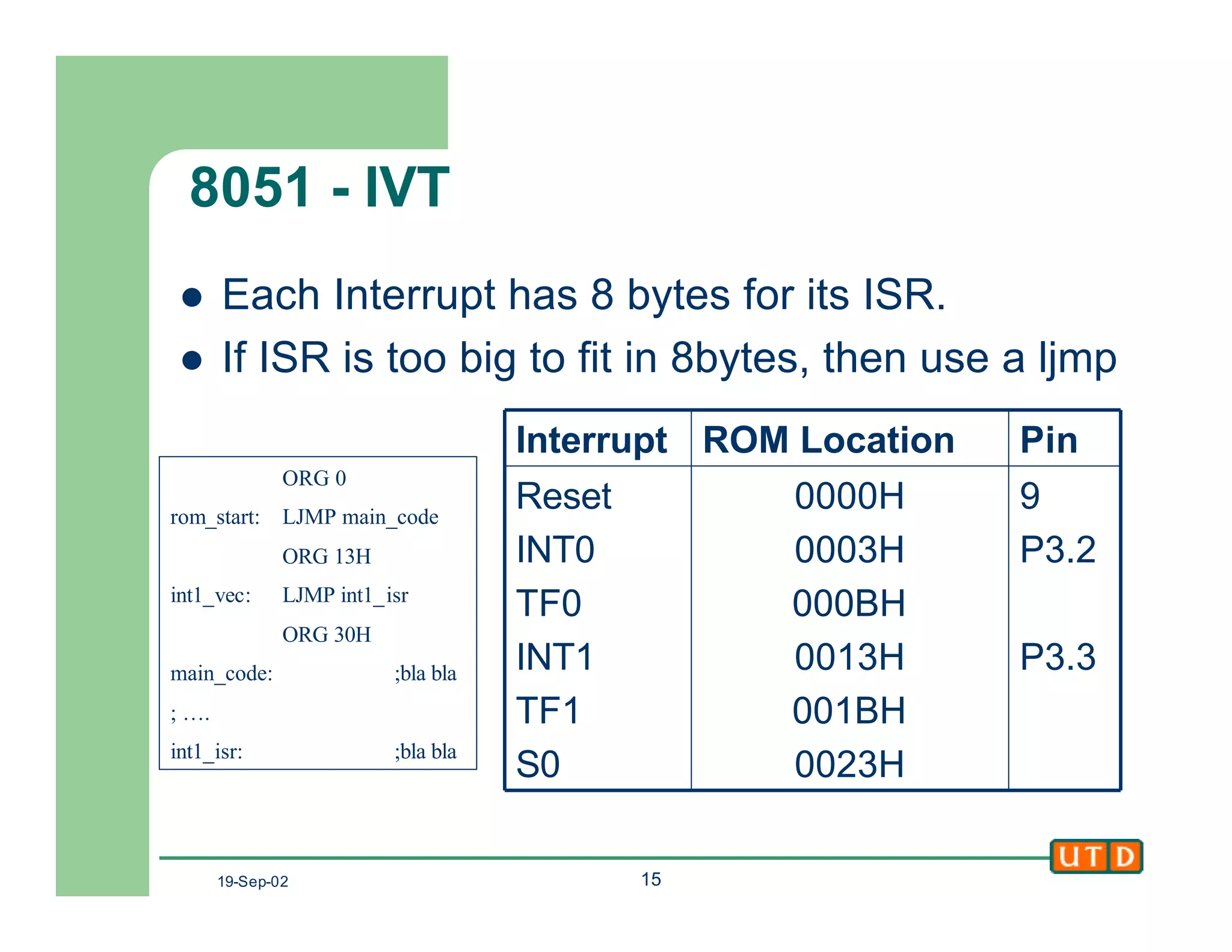
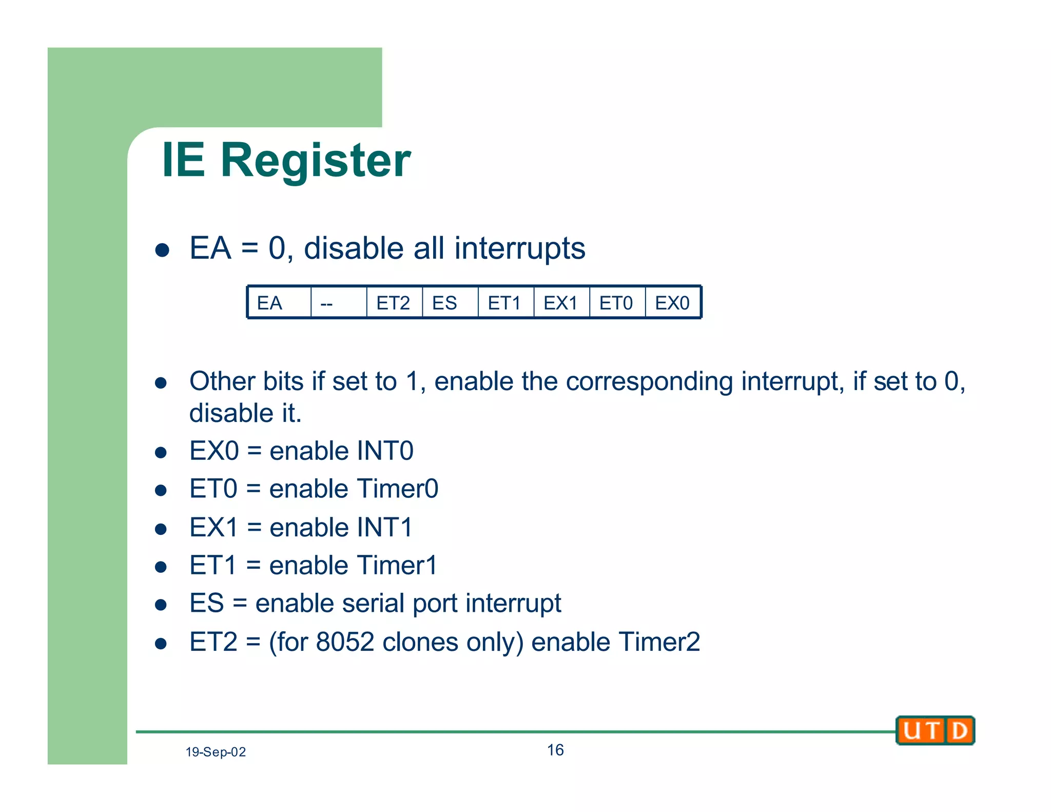
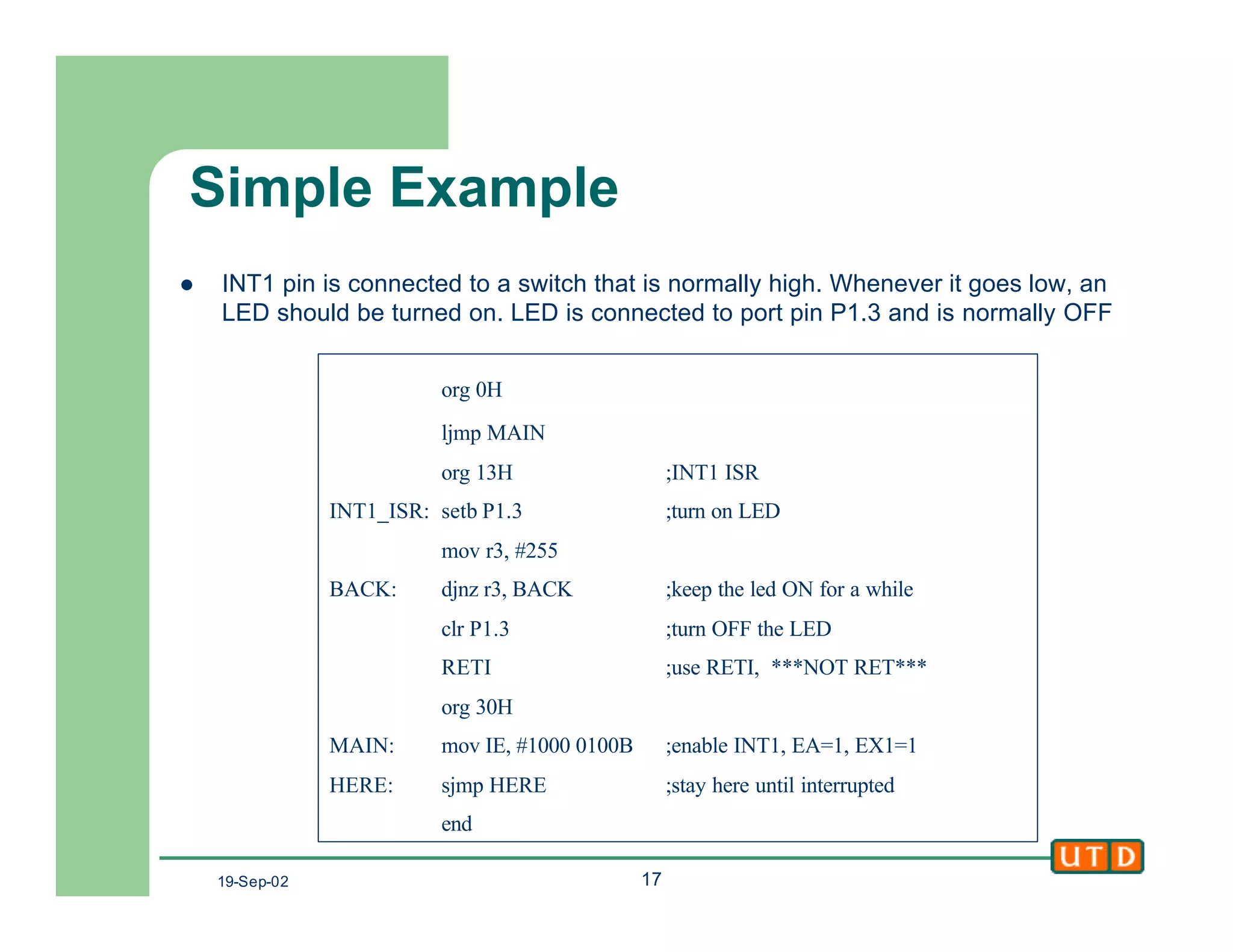
Downloaded 42 times
![19-Sep-02 4
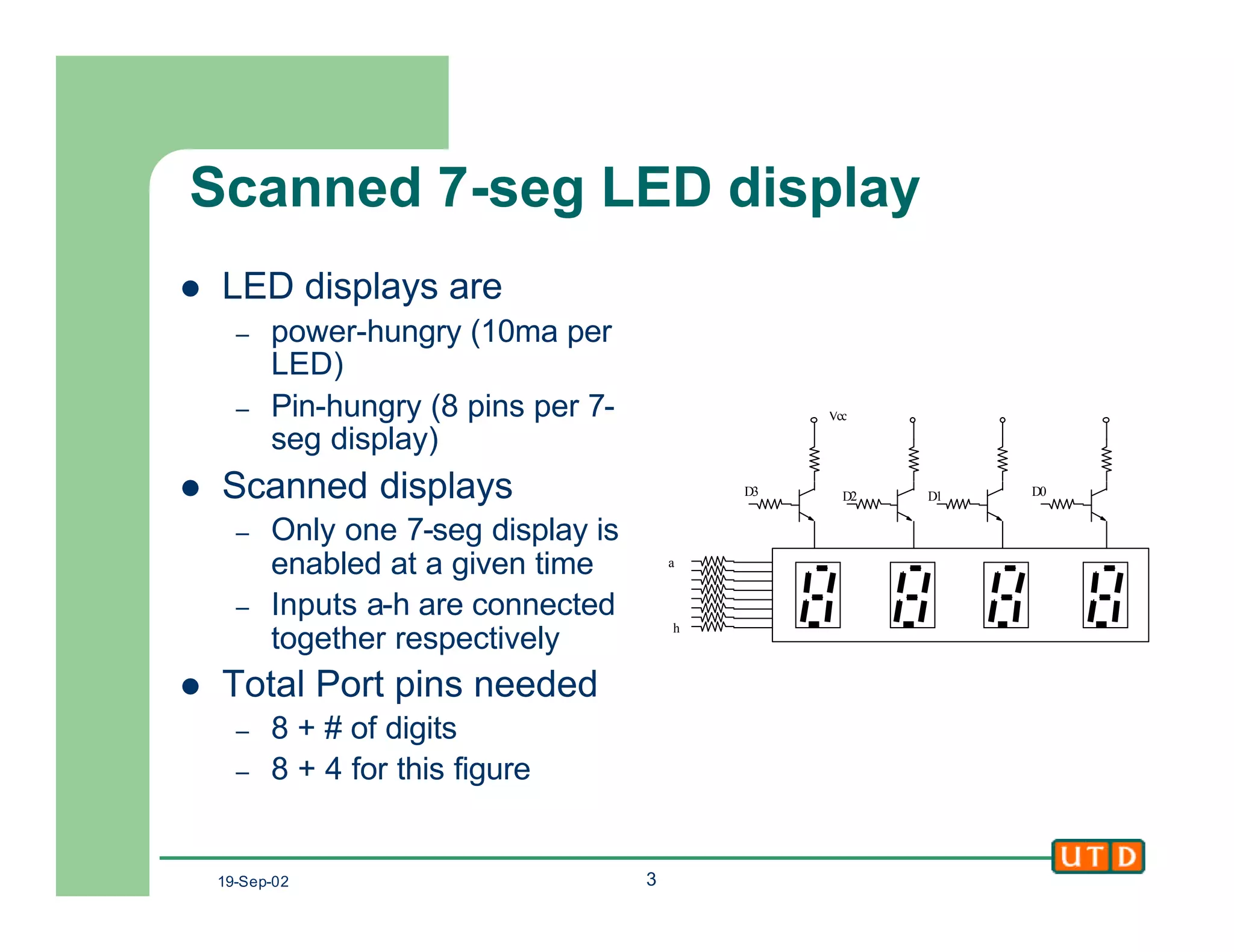
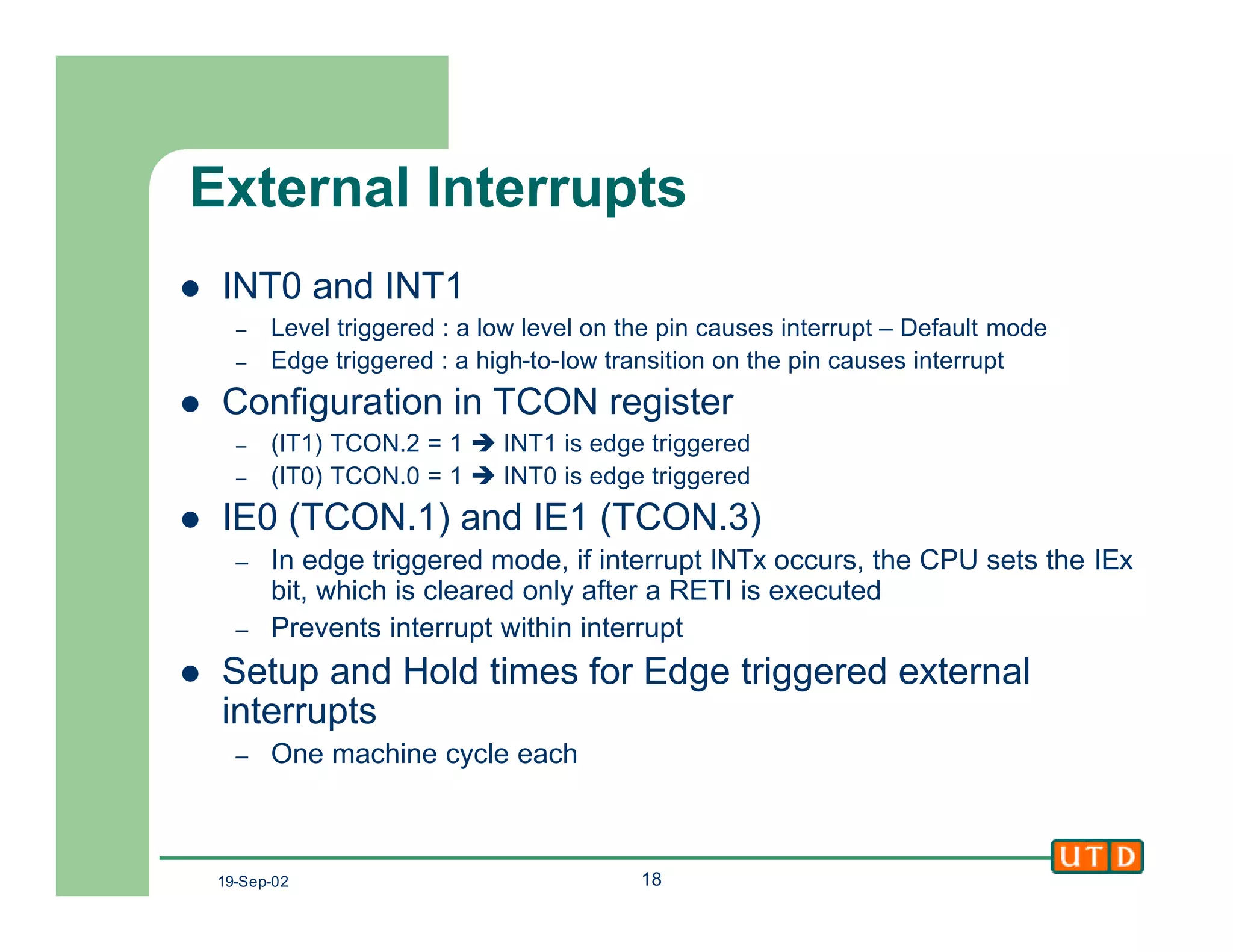
Scanned 7-seg display
l Algorithm to display a 4
digit value.
l The scanning frequency
should be high enough
to be flicker-free
– At least 30HZ
– Time one digit is ON
l 1/30 seconds
– Higher values give better
flicker reduction (60Hz)
start: disable [D3:D0]
again: enable D3
[a:h] ß pattern for Digit3
delay
disable D3. Enable D2
[a:h] ß pattern for Digit2
delay
disable D2. Enable D1
[a:h] ß pattern for Digit1
delay
disable D1. Enable D0
[a:h] ß pattern for Digit0
delay
disable D0
Goto again](https://image.slidesharecdn.com/class8-141216232308-conversion-gate02/75/Class8-4-2048.jpg)
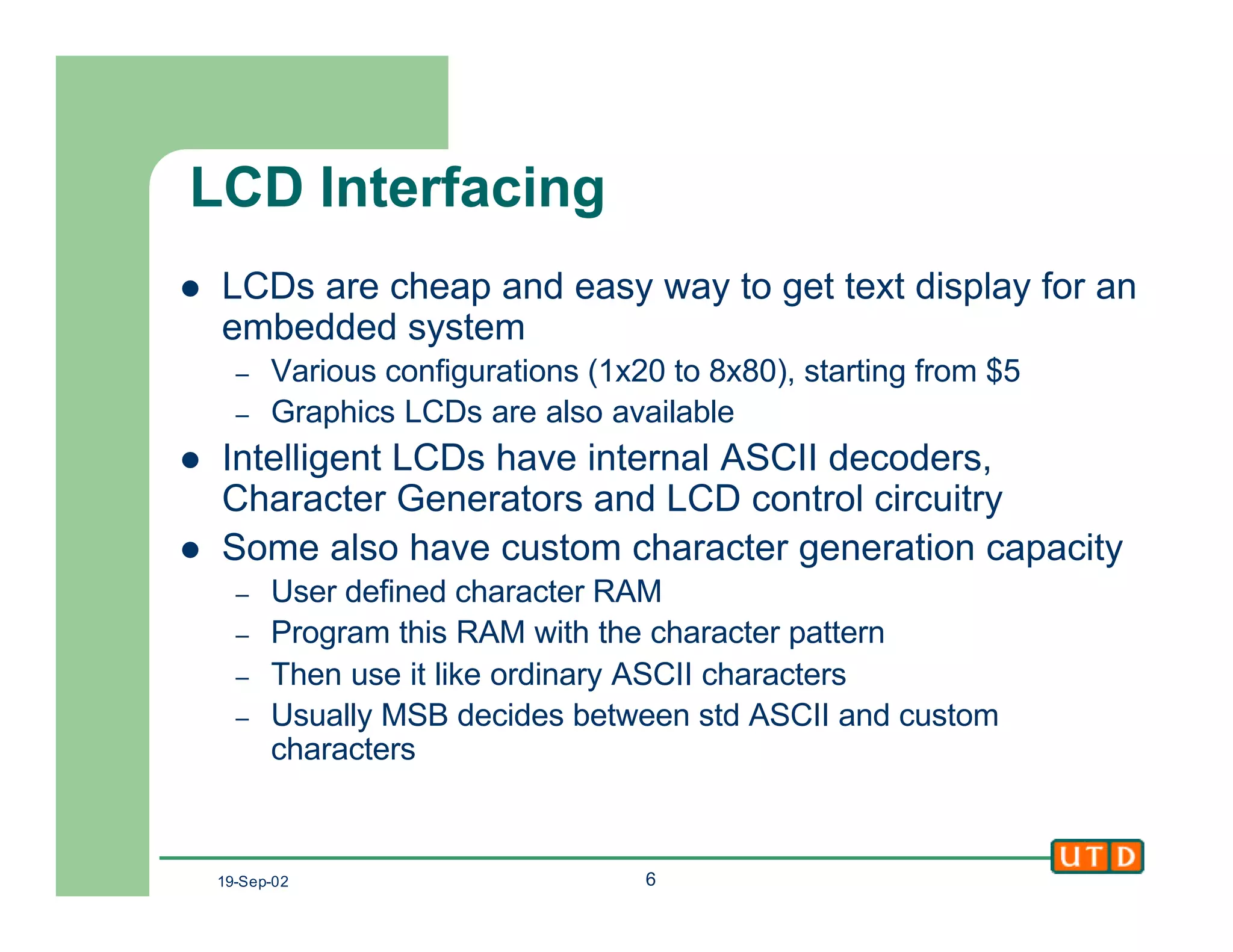
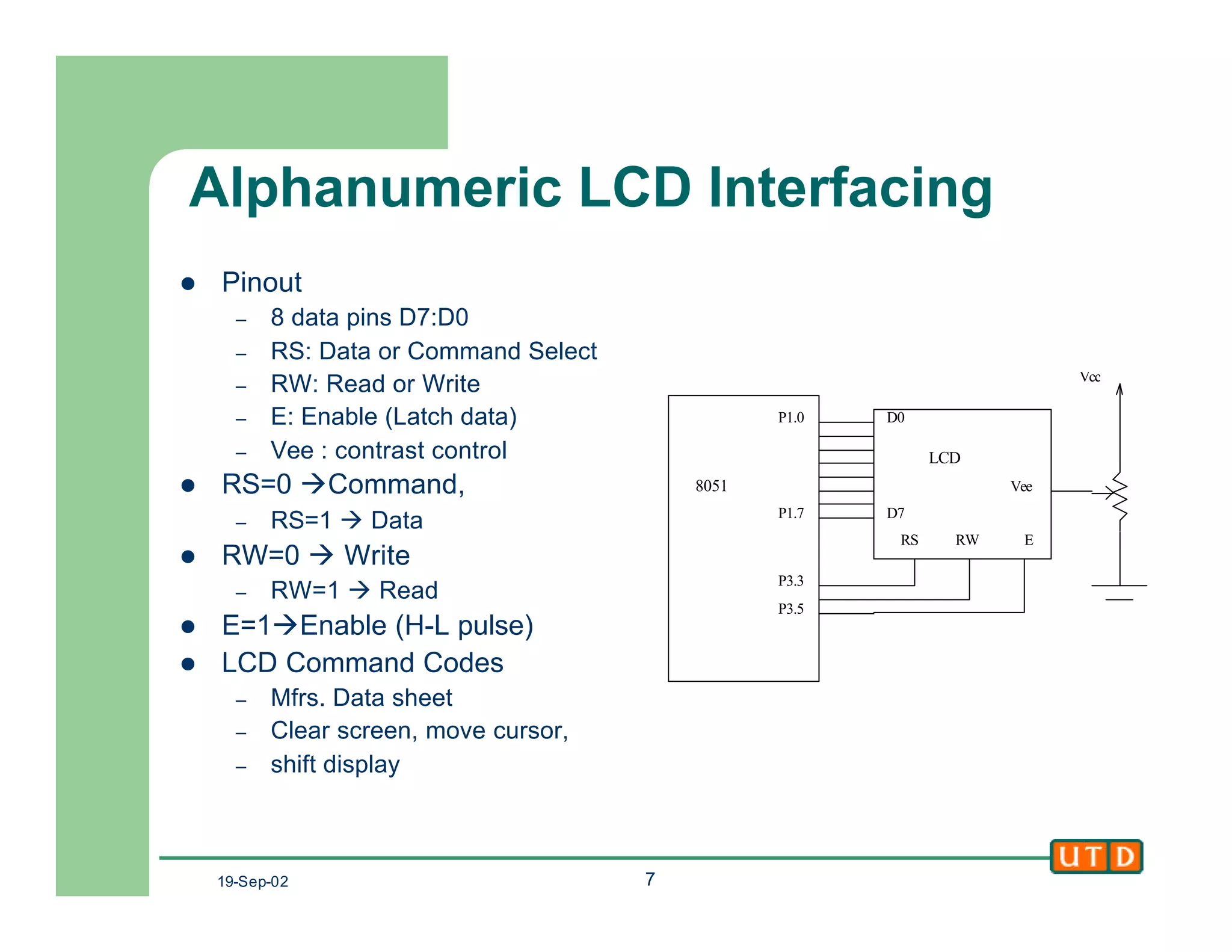
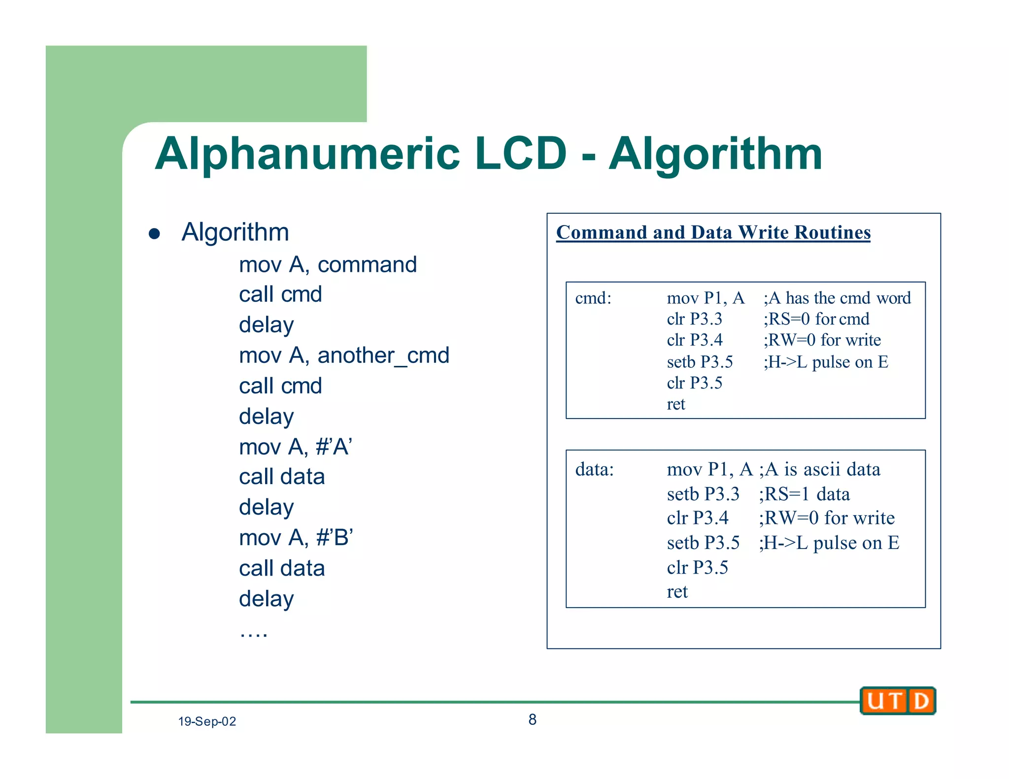
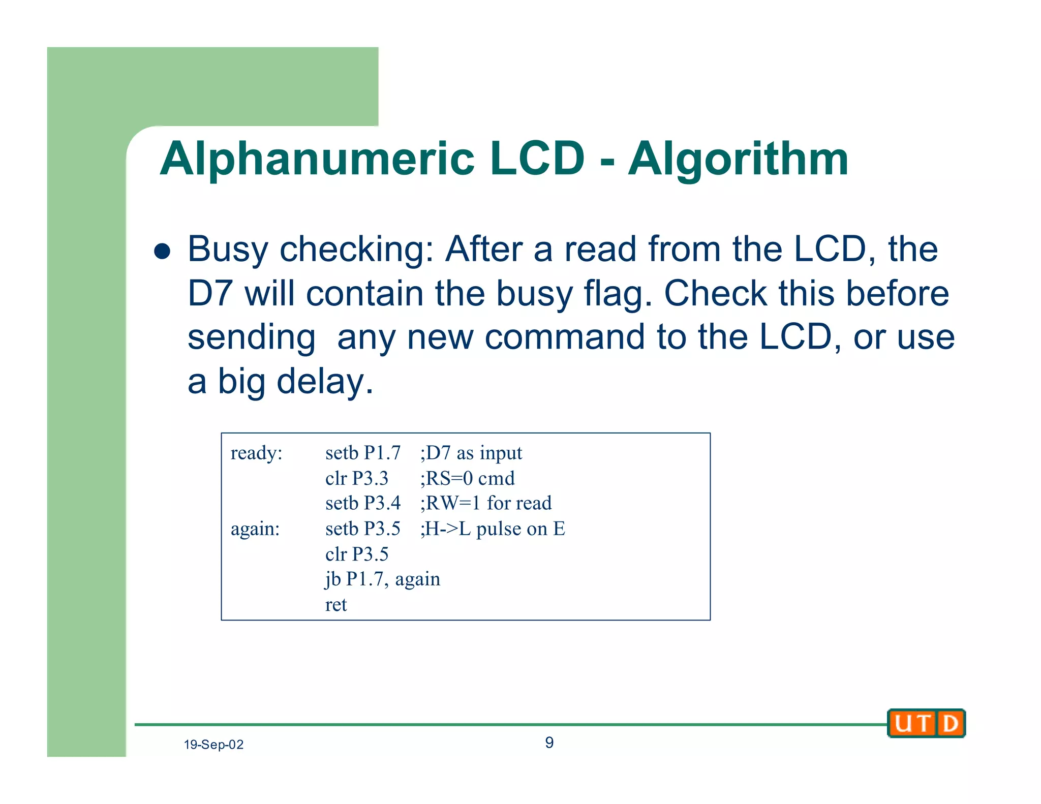

This document provides an overview of 8051 I/O interfacing and interrupts. It discusses scanned LED displays, LCD displays, keypads, and the 8051 interrupt vector table, interrupt service routines, interrupt enable register, external interrupts, and interrupt priority. Specific examples are given for interfacing 7-segment LED displays, keypads, and alphanumeric LCDs. Interrupts are compared to polling, and the execution of interrupts is explained.