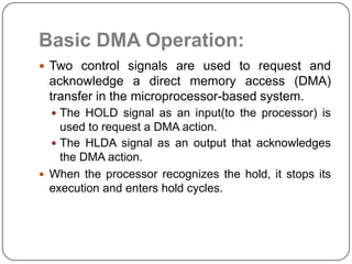
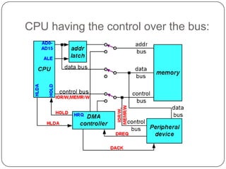
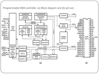
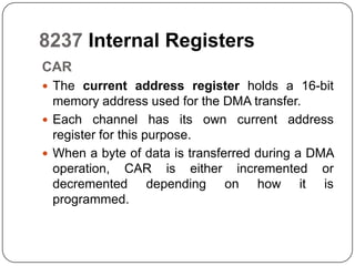
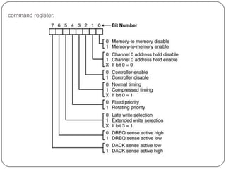
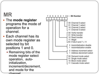
8237DMA CONTROLLER
Introduction:
 Direct Memory Access (DMA) is a method of
  allowing data to be moved from one location to
  another in a computer without intervention from
  the central processor (CPU).
 It is also a fast way of transferring data within
  (and sometimes between) computer.
 The DMA I/O technique provides direct access to
  the memory while the microprocessor is
  temporarily disabled.
 The DMA controller temporarily borrows the
  address bus, data bus and control bus from the
  microprocessor and transfers the data directly
  from the external devices to a series of memory
  locations (and vice versa).
Basic DMA Operation:
 Two control signals are used to request and
 acknowledge a direct memory access (DMA)
 transfer in the microprocessor-based system.
   The HOLD signal as an input(to the processor) is
    used to request a DMA action.
   The HLDA signal as an output that acknowledges
    the DMA action.
 When the processor recognizes the hold, it stops its
  execution and enters hold cycles.
Cont.,
 HOLD input has higher priority than INTR or NMI.
 The only microprocessor pin that has a higher
 priority than a HOLD is the RESET pin.
 HLDA  becomes active to indicate that the
 processor has placed its buses at high-
 impedance state.
Basic DMA Definitions:
 Direct memory accesses normally occur between
 an I/O device and memory without the use of the
 microprocessor.
  A DMA read transfers data from the memory
   to the I/O device.
  A DMA write transfers data from an I/O device
   to memory.
 The system contains separate memory and I/O
  control signals.
 Hence the Memory & the I/O are controlled
  simultaneously
 The DMA controller provides memory with its address,
    and the controller signal selects the I/O device during
    the transfer.
   Data transfer speed is determined by speed of the
    memory device or a DMA controller.
   In many cases, the DMA controller slows the speed of
    the system when transfers occur.
   The serial PCI (Peripheral Component Interface)
    Express bus transfers data at rates exceeding DMA
    transfers.
   This in modern systems has made DMA is less
    important.
6
The 8237 DMA Controller
 The 8237 supplies memory & I/O with control
  signals and memory address information during
  the DMA transfer.
 It is actually a special-purpose microprocessor
  whose job is high-speed data transfer between
  memory and I/O
CPU having the control over the bus:
When DMA operates:
 8237 is not a discrete component in modern
  microprocessor-based systems.
   It appears within many system controller chip
    sets
 8237 is a four-channel device compatible with
  8086/8088, adequate for small systems.
 Expandable to any number of DMA channel
     inputs
 8237 is capable of DMA transfers at rates up
     to 1.6MB per second.
 Each channel is capable of addressing a
10                          full
Programmable DMA controller. (a) Block diagram and (b) pin-out.


11
8237 Internal Registers
CAR
 The current address register holds a 16-bit
  memory address used for the DMA transfer.
 Each channel has its own current address
  register for this purpose.
 When a byte of data is transferred during a DMA
  operation, CAR is either incremented or
  decremented depending on how it is
  programmed.
CWCR
 The current word count register programs a
 channel for the number of bytes to transferred
 during a DMA action.
CR
 The command register programs the operation
  of the 8237 DMA controller.
 The register uses bit position 0 to select the
  memory-to-memory DMA transfer mode.
   Memory-to-memory       DMA transfers use DMA
    channel 0 to hold the source address
   DMA channel 1 holds the destination address
command register.


14
BA and BWC
 The base address (BA) and base word count
  (BWC) registers are used when auto-initialization
  is selected for a channel.
 In auto-initialization mode, these registers are
  used to reload the CAR and CWCR after the
  DMA action is completed.
MR
 The mode register
  programs the mode of
  operation for a
  channel.
 Each channel has its
  own mode register as
  selected by bit
  positions 1 and 0.
      Remaining bits of the
      mode register select
      operation, auto-
      initialization,
      increment/decrement,
16    and mode for the
BR
 The bus request register is used to request
     a DMA transfer via software.
      very useful in memory-to-memory transfers, where an
      external signal is not available to begin the DMA transfer


17
MRSR
 The mask register set/reset sets or clears the channel
     mask.
      if the mask is set, the channel is disabled
      the RESET signal sets all channel masks
      to disable them


18
MSR
 The mask register clears or sets all of
     the masks with one command instead of individual
     channels, as with the MRSR.


19
SR
 The status register shows
  status of each DMA
  channel. The TC bits
  indicate if the channel has
  reached its terminal count
  (transferred all its bytes).
 When the terminal count is
  reached, the DMA transfer
  is terminated for most
  modes
  of operation.
 The request bits indicate
  whether
20
     the DREQ input for a given
Master clear
 Acts exactly the same as the RESET signal to the 8237.
   As with the RESET signal, this command disables all
    channels
Clear mask register
 Enables all four DMA channels.
Clear the first/last flip-flop
 Clears the first/last (F/L) flip-flop within 8237.
 The F/L flip-flop selects which byte (low or high order) is
  read/written in the current address and current count
  registers.
   if F/L = 0, the low-order byte is selected
   if F/L = 1, the high-order byte is selected
 Any read or write to the address or count register
 Memory-to-memory transfer is much more
  powerful than the automatically repeated
  MOVSB instruction.
   most modern chip sets do not support the
    memory-to-memory feature
 8237 requires only 2.0 µs per byte, which is
  over twice as fast the existing data transfer.


22

8237 dma controller

  • 1.
  • 2.
    Introduction:  Direct MemoryAccess (DMA) is a method of allowing data to be moved from one location to another in a computer without intervention from the central processor (CPU).  It is also a fast way of transferring data within (and sometimes between) computer.  The DMA I/O technique provides direct access to the memory while the microprocessor is temporarily disabled.  The DMA controller temporarily borrows the address bus, data bus and control bus from the microprocessor and transfers the data directly from the external devices to a series of memory locations (and vice versa).
  • 3.
    Basic DMA Operation: Two control signals are used to request and acknowledge a direct memory access (DMA) transfer in the microprocessor-based system.  The HOLD signal as an input(to the processor) is used to request a DMA action.  The HLDA signal as an output that acknowledges the DMA action.  When the processor recognizes the hold, it stops its execution and enters hold cycles.
  • 4.
    Cont.,  HOLD inputhas higher priority than INTR or NMI.  The only microprocessor pin that has a higher priority than a HOLD is the RESET pin.  HLDA becomes active to indicate that the processor has placed its buses at high- impedance state.
  • 5.
    Basic DMA Definitions: Direct memory accesses normally occur between an I/O device and memory without the use of the microprocessor.  A DMA read transfers data from the memory to the I/O device.  A DMA write transfers data from an I/O device to memory.  The system contains separate memory and I/O control signals.  Hence the Memory & the I/O are controlled simultaneously
  • 6.
     The DMAcontroller provides memory with its address, and the controller signal selects the I/O device during the transfer.  Data transfer speed is determined by speed of the memory device or a DMA controller.  In many cases, the DMA controller slows the speed of the system when transfers occur.  The serial PCI (Peripheral Component Interface) Express bus transfers data at rates exceeding DMA transfers.  This in modern systems has made DMA is less important. 6
  • 7.
    The 8237 DMAController  The 8237 supplies memory & I/O with control signals and memory address information during the DMA transfer.  It is actually a special-purpose microprocessor whose job is high-speed data transfer between memory and I/O
  • 8.
    CPU having thecontrol over the bus:
  • 9.
  • 10.
     8237 isnot a discrete component in modern microprocessor-based systems.  It appears within many system controller chip sets  8237 is a four-channel device compatible with 8086/8088, adequate for small systems.  Expandable to any number of DMA channel inputs  8237 is capable of DMA transfers at rates up to 1.6MB per second.  Each channel is capable of addressing a 10 full
  • 11.
    Programmable DMA controller.(a) Block diagram and (b) pin-out. 11
  • 12.
    8237 Internal Registers CAR The current address register holds a 16-bit memory address used for the DMA transfer.  Each channel has its own current address register for this purpose.  When a byte of data is transferred during a DMA operation, CAR is either incremented or decremented depending on how it is programmed.
  • 13.
    CWCR  The currentword count register programs a channel for the number of bytes to transferred during a DMA action. CR  The command register programs the operation of the 8237 DMA controller.  The register uses bit position 0 to select the memory-to-memory DMA transfer mode.  Memory-to-memory DMA transfers use DMA channel 0 to hold the source address  DMA channel 1 holds the destination address
  • 14.
  • 15.
    BA and BWC The base address (BA) and base word count (BWC) registers are used when auto-initialization is selected for a channel.  In auto-initialization mode, these registers are used to reload the CAR and CWCR after the DMA action is completed.
  • 16.
    MR  The moderegister programs the mode of operation for a channel.  Each channel has its own mode register as selected by bit positions 1 and 0.  Remaining bits of the mode register select operation, auto- initialization, increment/decrement, 16 and mode for the
  • 17.
    BR  The busrequest register is used to request a DMA transfer via software.  very useful in memory-to-memory transfers, where an external signal is not available to begin the DMA transfer 17
  • 18.
    MRSR  The maskregister set/reset sets or clears the channel mask.  if the mask is set, the channel is disabled  the RESET signal sets all channel masks to disable them 18
  • 19.
    MSR  The maskregister clears or sets all of the masks with one command instead of individual channels, as with the MRSR. 19
  • 20.
    SR  The statusregister shows status of each DMA channel. The TC bits indicate if the channel has reached its terminal count (transferred all its bytes).  When the terminal count is reached, the DMA transfer is terminated for most modes of operation.  The request bits indicate whether 20 the DREQ input for a given
  • 21.
    Master clear  Actsexactly the same as the RESET signal to the 8237.  As with the RESET signal, this command disables all channels Clear mask register  Enables all four DMA channels. Clear the first/last flip-flop  Clears the first/last (F/L) flip-flop within 8237.  The F/L flip-flop selects which byte (low or high order) is read/written in the current address and current count registers.  if F/L = 0, the low-order byte is selected  if F/L = 1, the high-order byte is selected  Any read or write to the address or count register
  • 22.
     Memory-to-memory transferis much more powerful than the automatically repeated MOVSB instruction.  most modern chip sets do not support the memory-to-memory feature  8237 requires only 2.0 µs per byte, which is over twice as fast the existing data transfer. 22