Download as PDF, PPTX


![26-Sep-02 16
8051 Dev System Survey
l Paul’s 8051 Dev Board [http://www.pjrc.com]
– 87C52, 22MHz, 2 8255 devices, 50 I/O lines, LCD header, 30K Flash,
32K SRAM, proto area, 2 serial ports, ~80$ assembled
l Axman CME552 and CME562 [http://www.axman.com/]
– S80C552-12 CPU, 32K each of EPROM, EEPROM and SRAM, 8 A/D
inputs, 2 PWM outputs, LCD and keypad interface, 20 I/O lines, proto
area, ~120$
l New Micros [http://www.newmicros.com/]
– Many products, all have proto area, Cost from 40$ to 180$
l Bipom [http://www.bipom.com/]
– Many products, very small, no proto area, uses atmel devices with
onboard Flash and SRAM, ISP, LCD and keypad interface, 40 to 70$
l Tecel [http://www.tecel.com/t1/]
– Many products. Very small, upto 32K SRAM and EEPROM, many I/O
lines, No proto area, $40 to $70. T1 bare board is 12$ !](https://image.slidesharecdn.com/class10-141216232309-conversion-gate01/85/Class10-16-320.jpg)


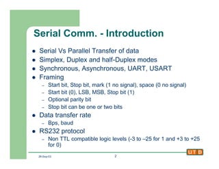
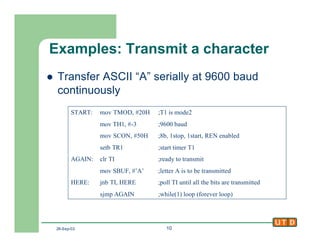
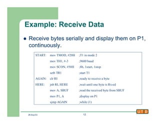
This document discusses serial communication using the 8051 microcontroller. It begins by introducing serial vs parallel data transfer, communication modes, and framing. It then describes the RS-232 protocol and pinout when using the 8051 UART. Setting the baud rate using Timer 1 is explained. The document provides details on the Serial Control Register and transmitting and receiving data with the serial port. It concludes by discussing using interrupts with the serial port and providing an example of transmitting data from Port 1 and receiving to Port 0 using interrupts.