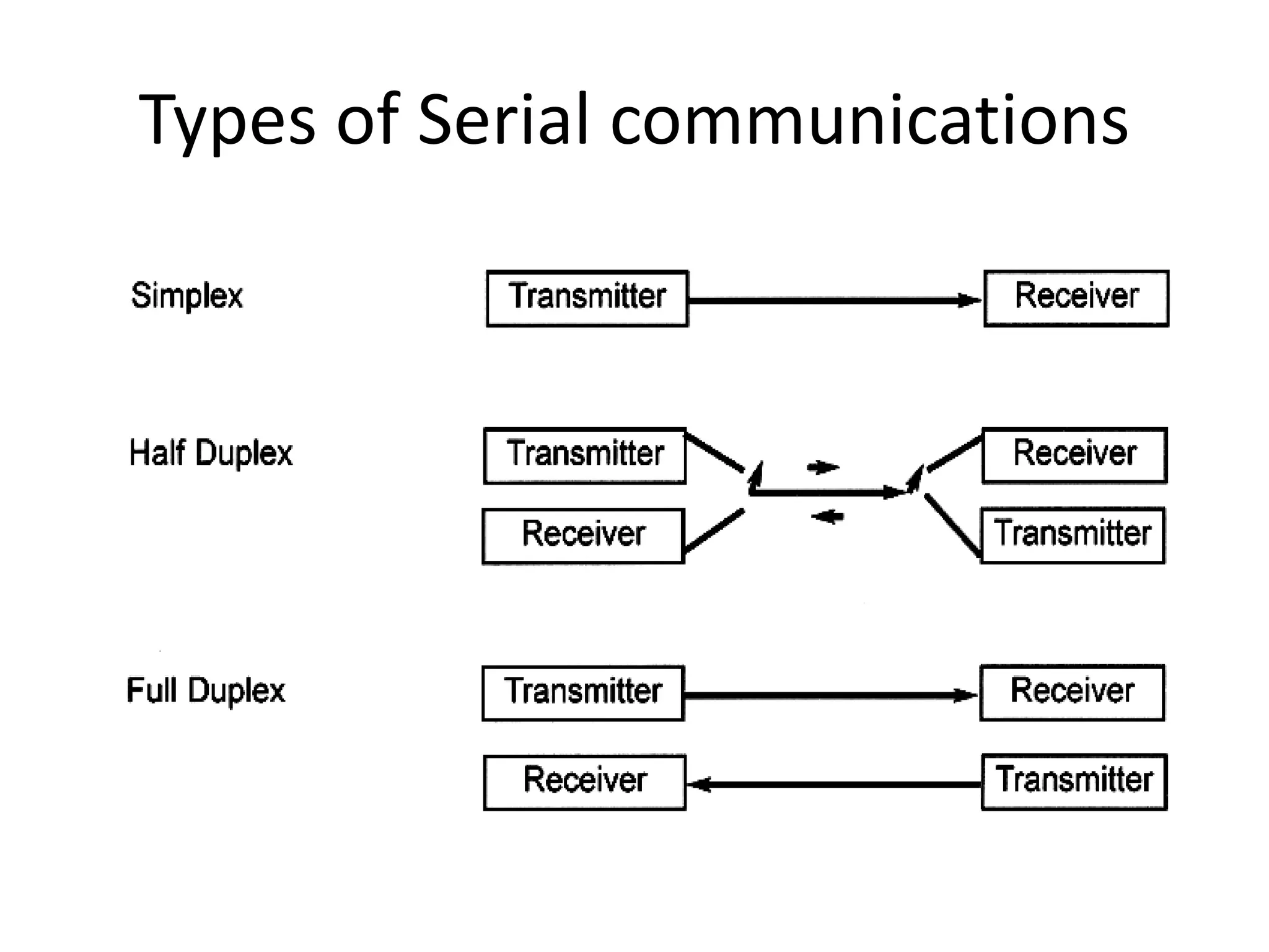
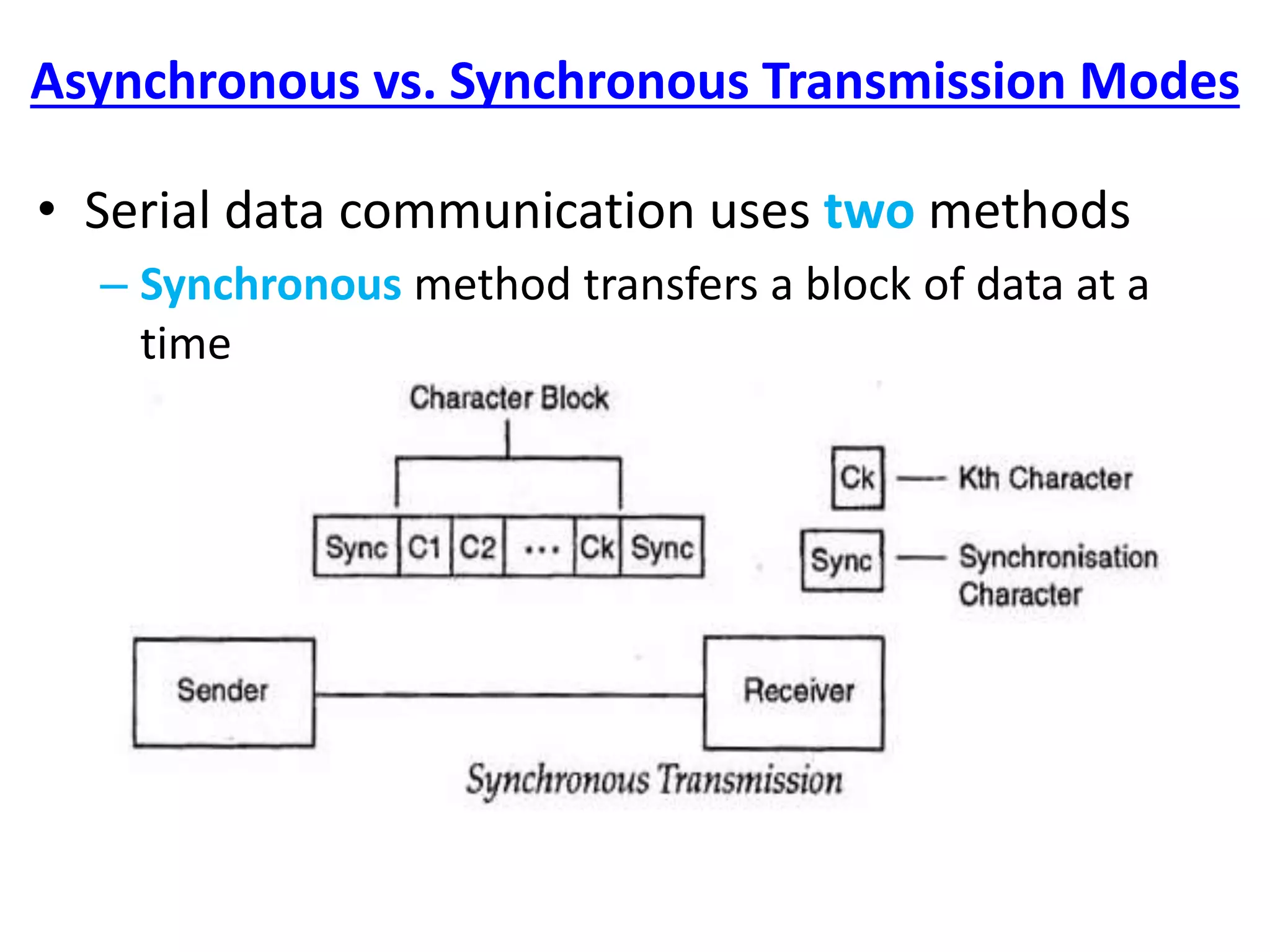
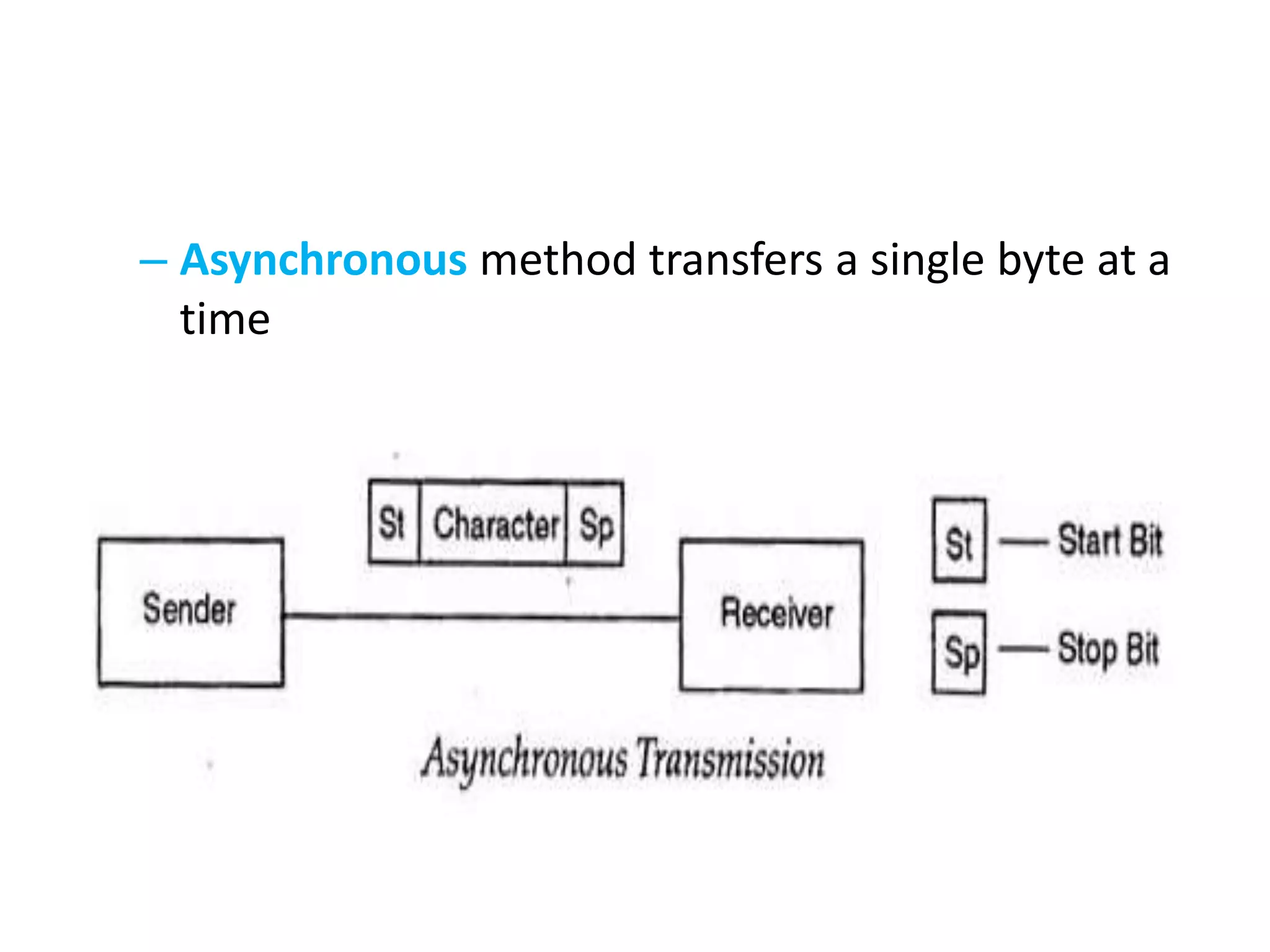
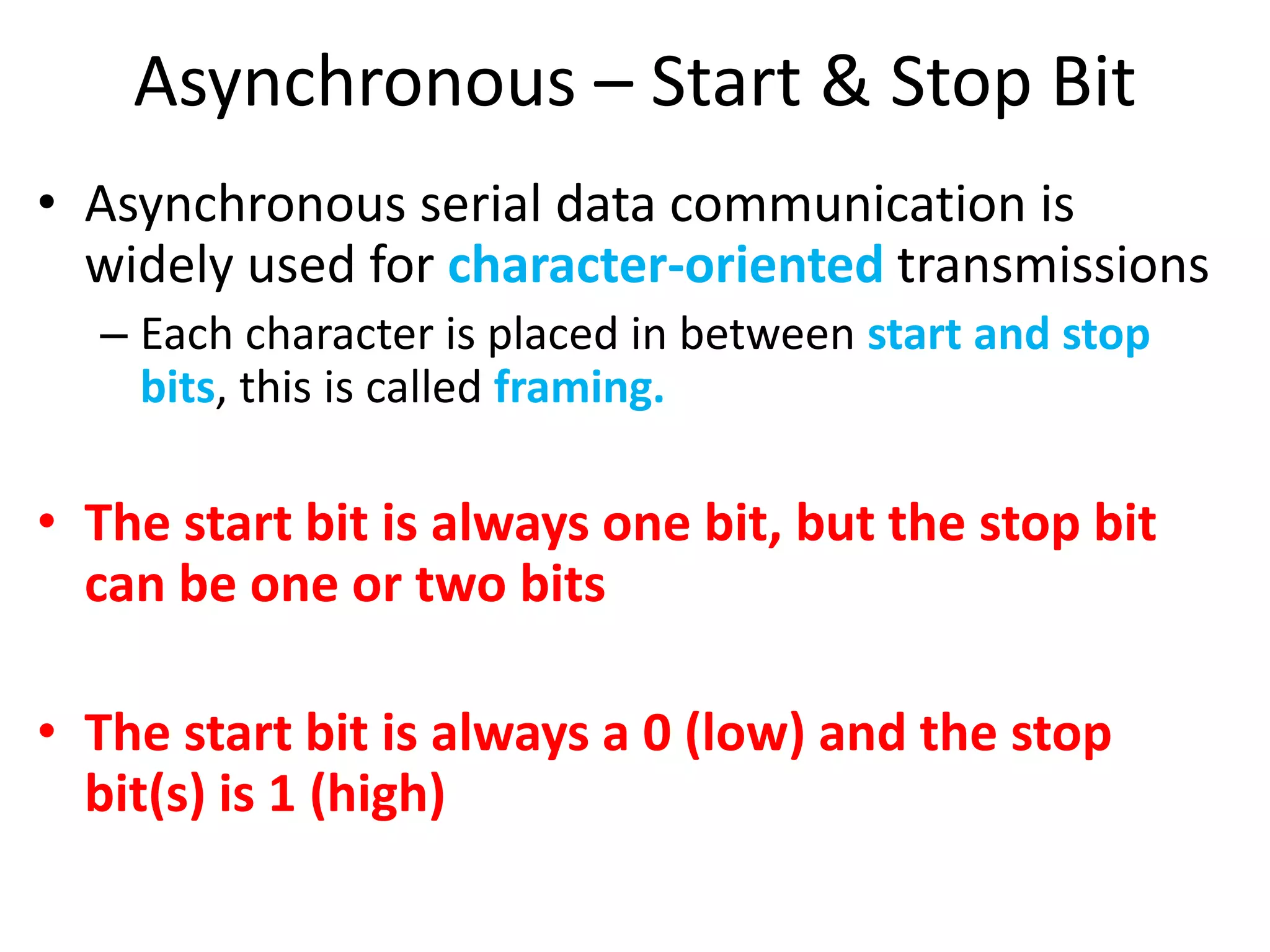
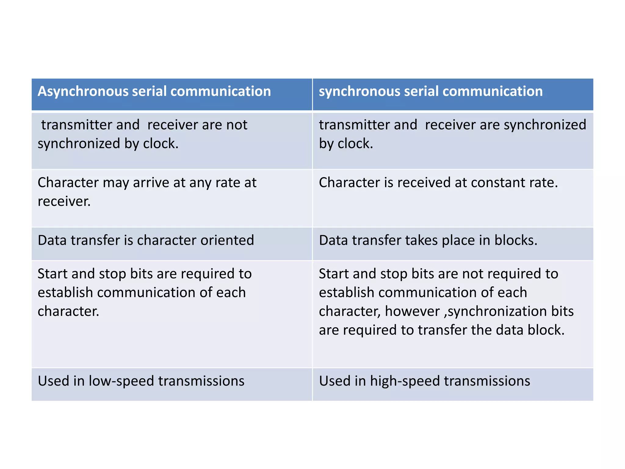
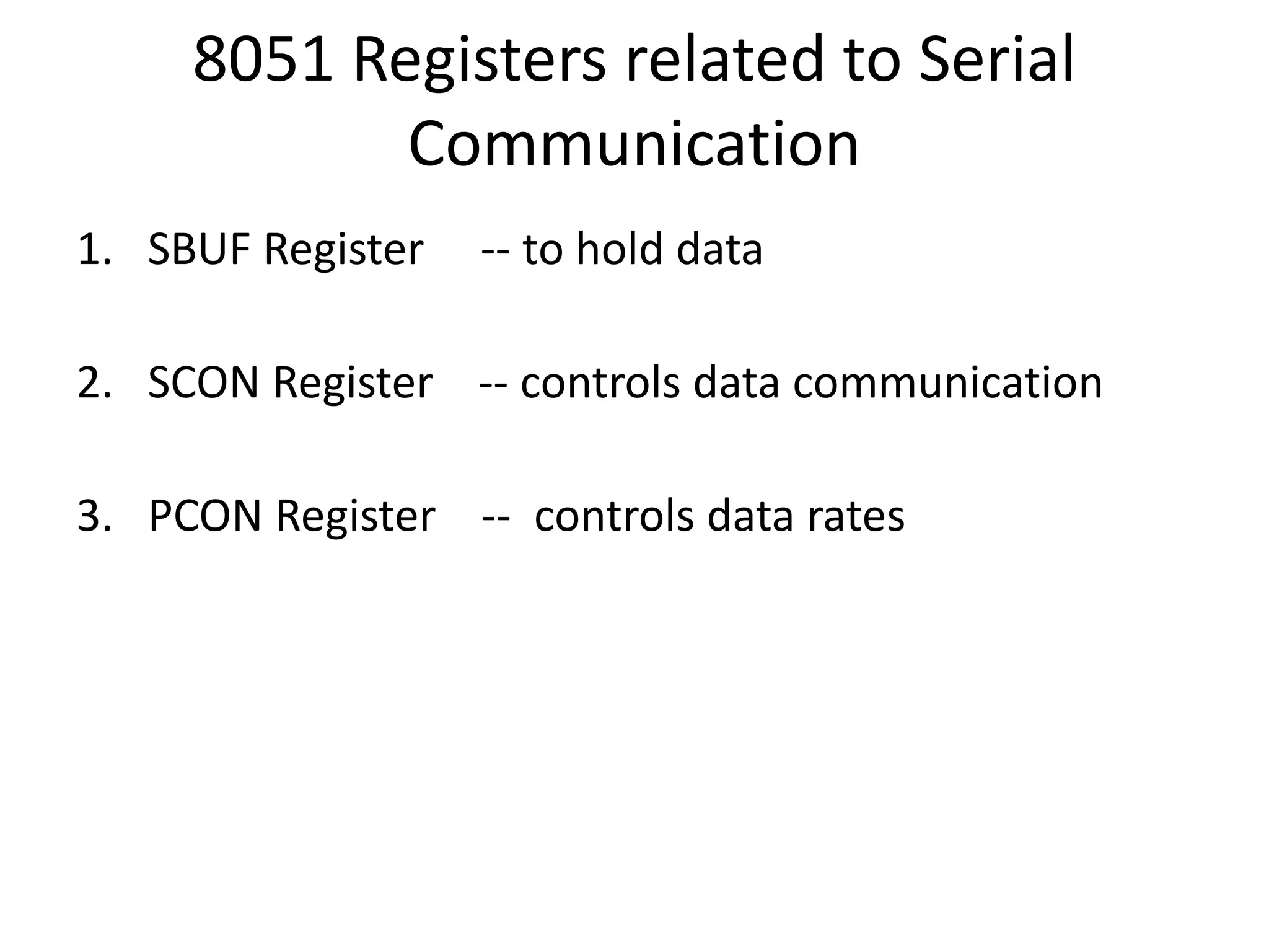
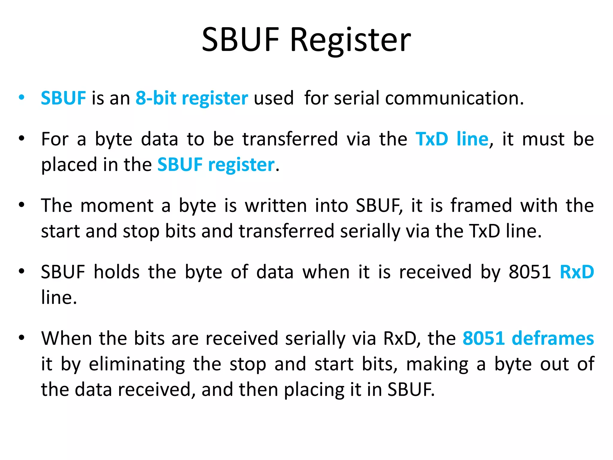
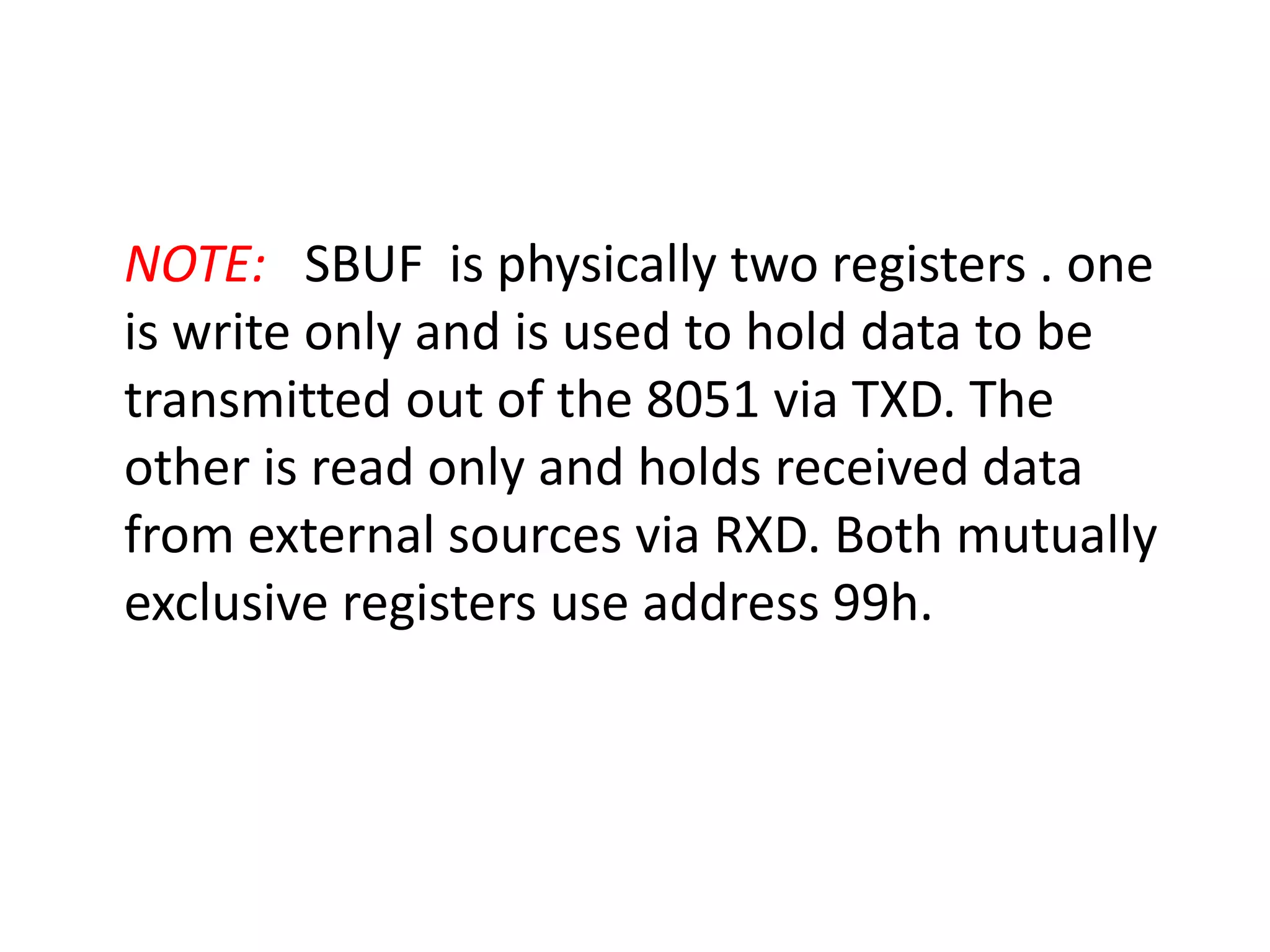
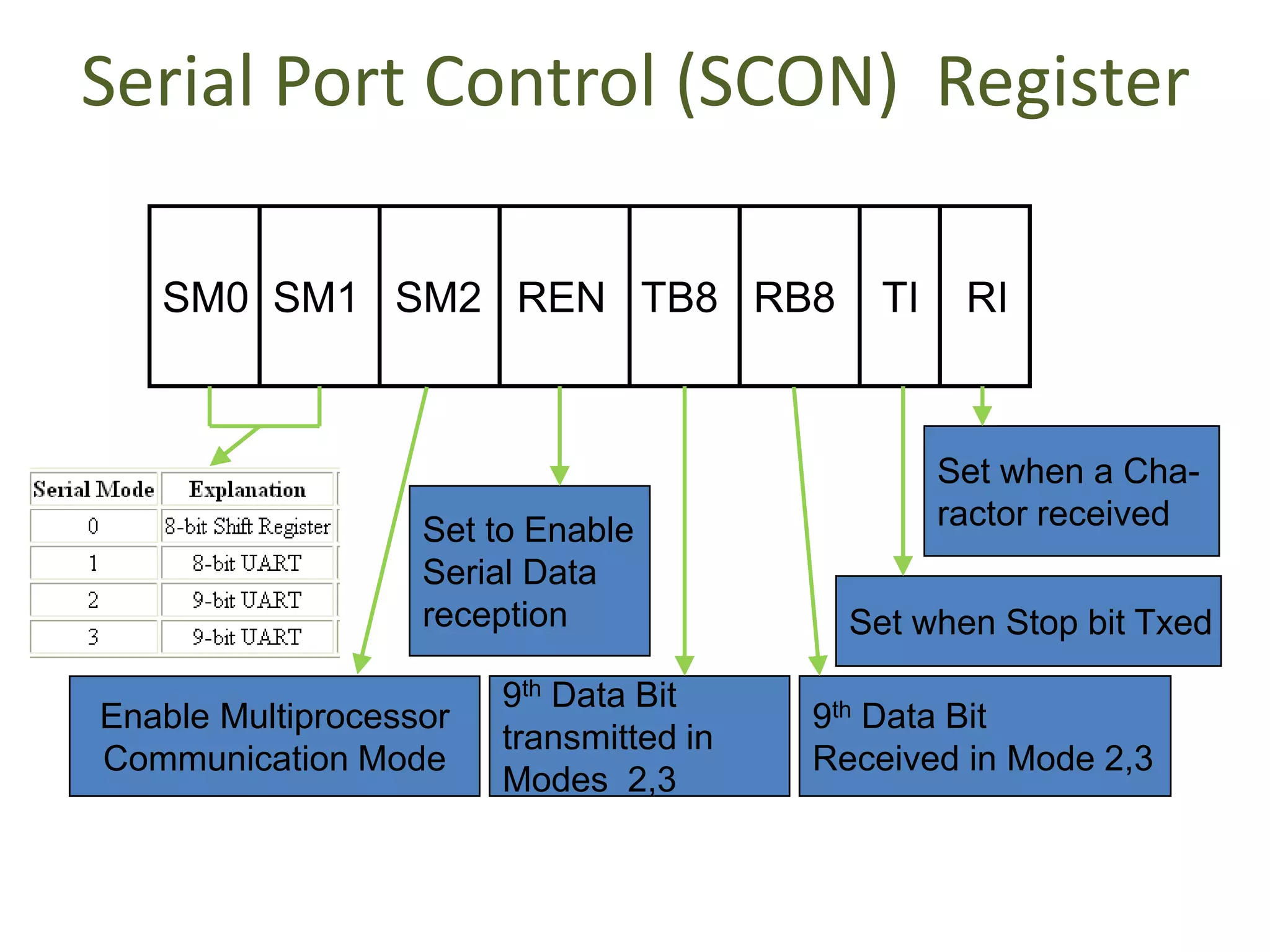
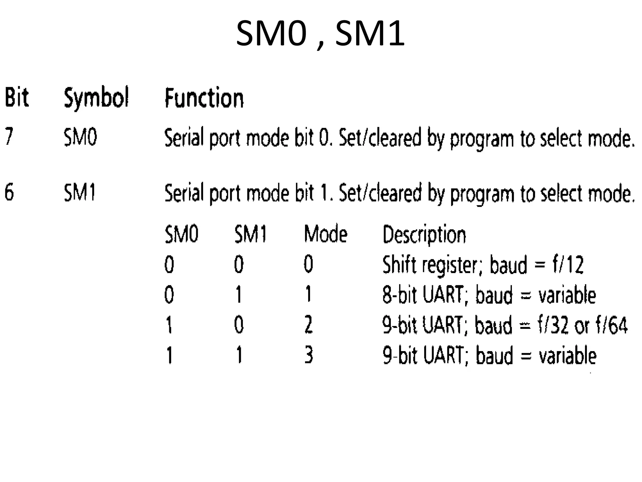
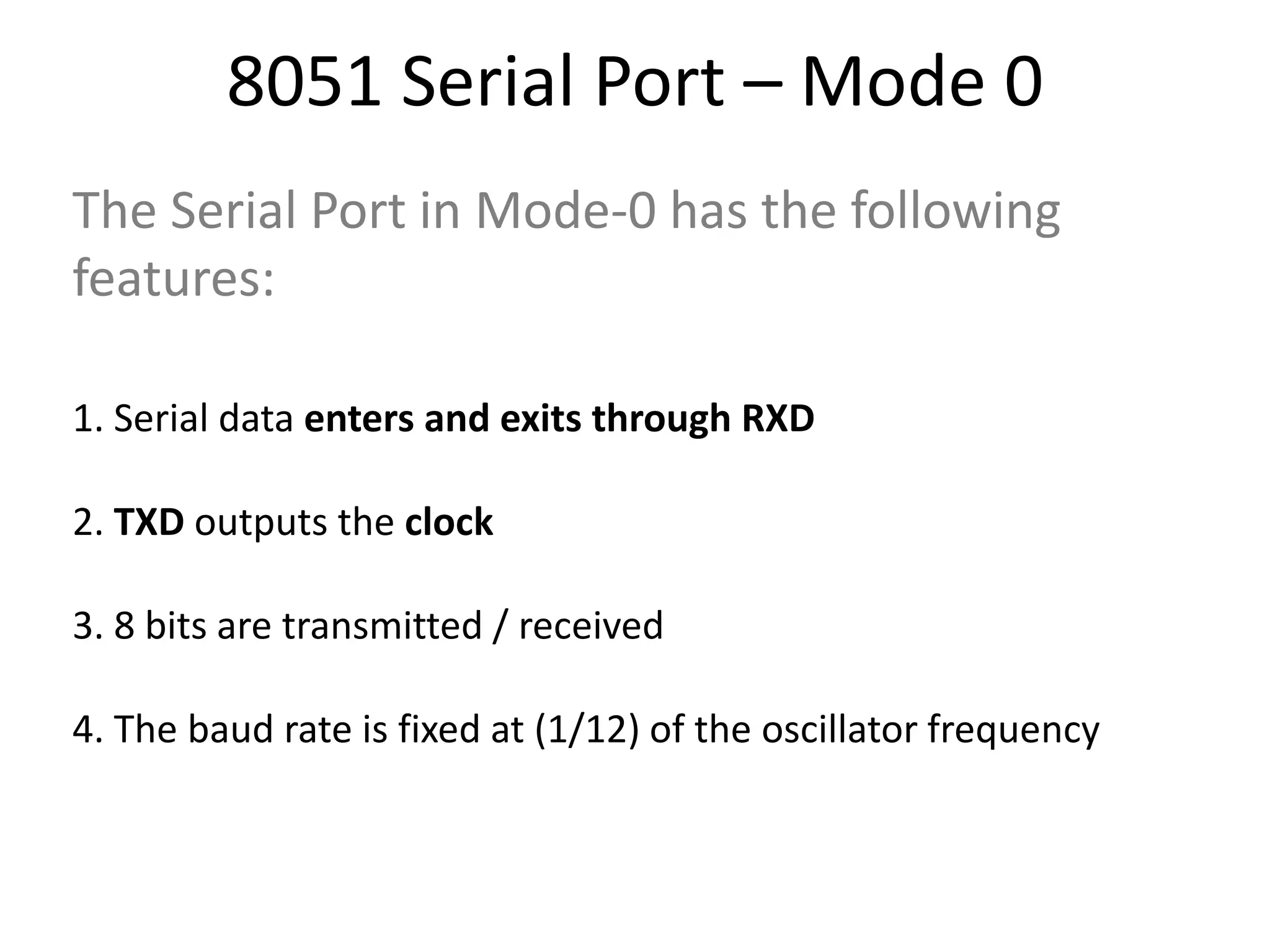
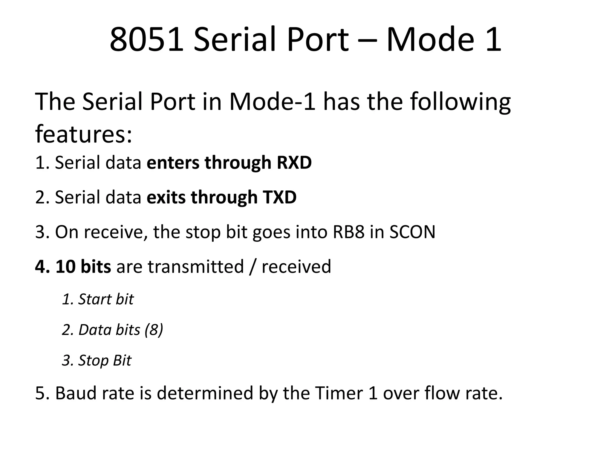
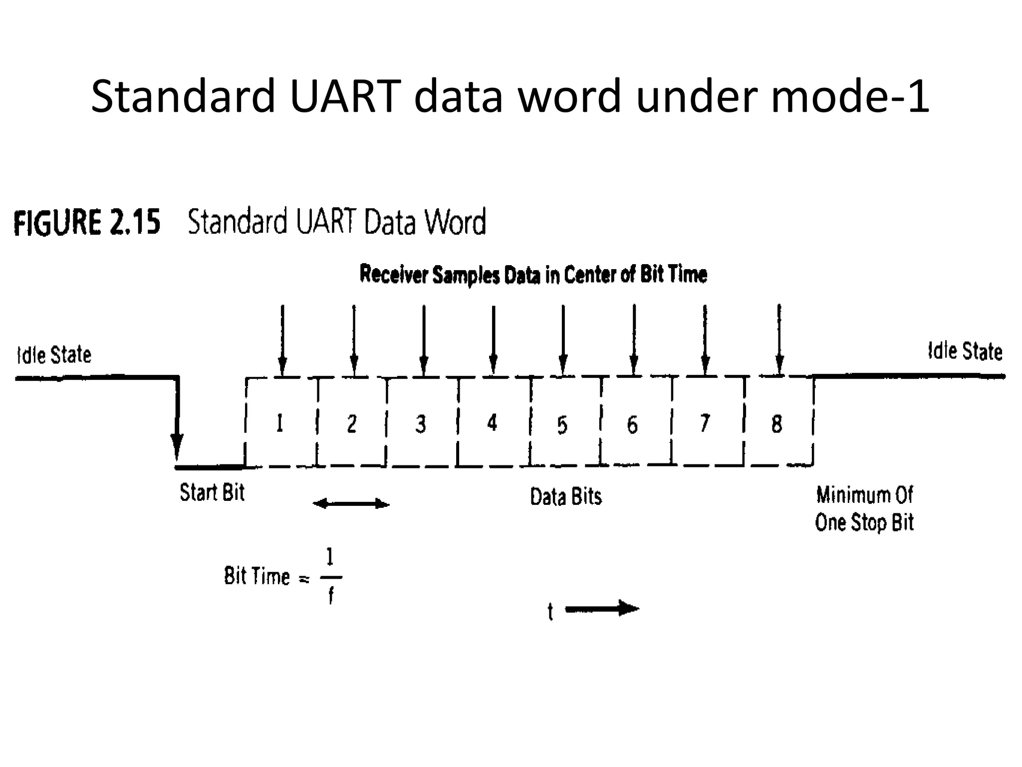
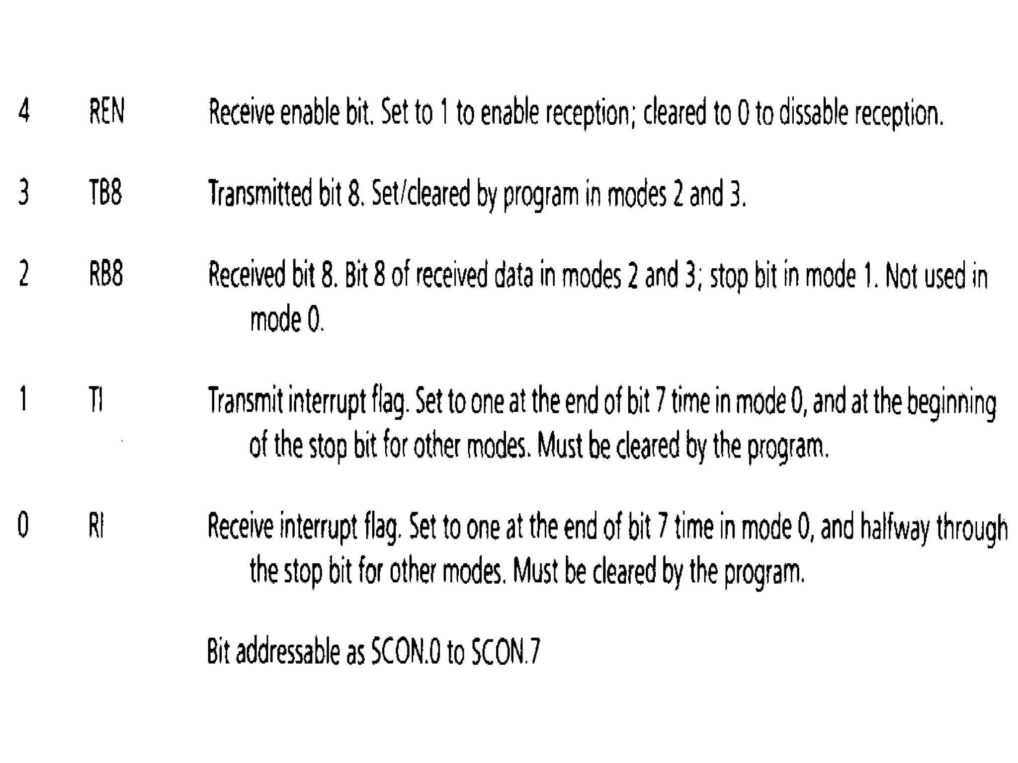
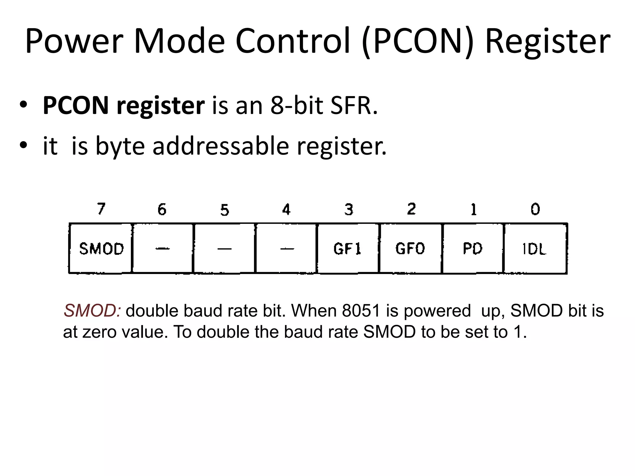
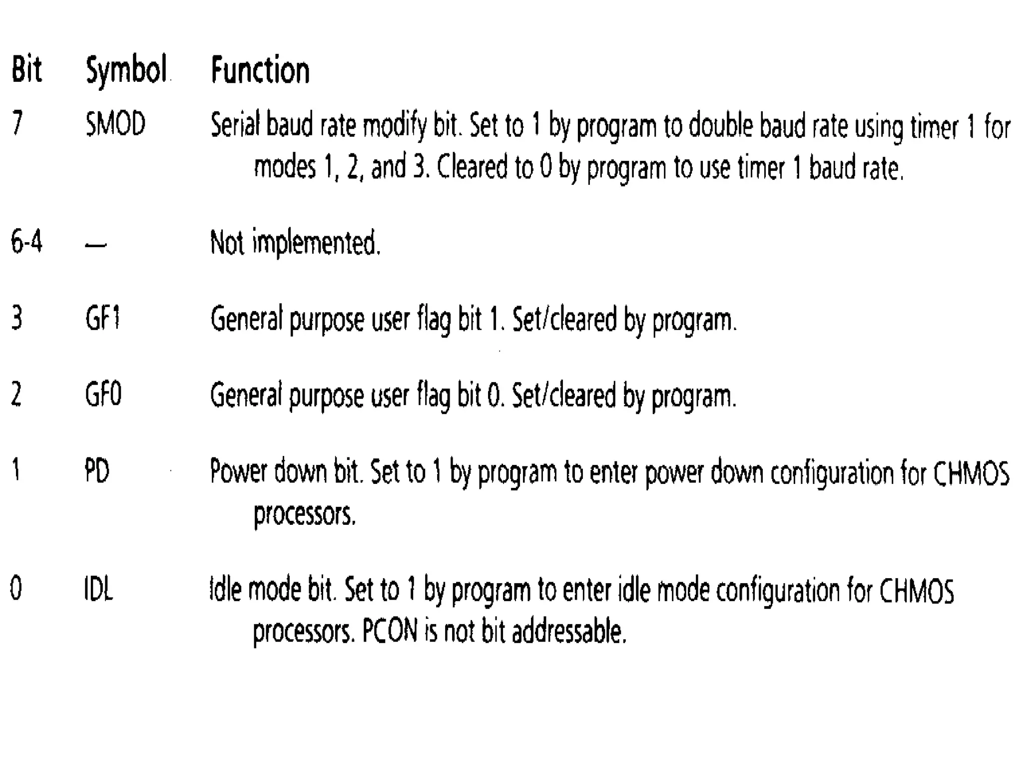
6. Asynchronous vs. Synchronous Transmission Modes
• Serial data communication uses two methods
– Synchronous method transfers a block of data at a
time
8. Asynchronous – Start & Stop Bit
• Asynchronous serial data communication is
widely used for character-oriented transmissions
– Each character is placed in between start and stop
bits, this is called framing.
• The start bit is always one bit, but the stop bit
can be one or two bits
• The start bit is always a 0 (low) and the stop
bit(s) is 1 (high)
9. Asynchronous serial communication synchronous serial communication
transmitter and receiver are not
synchronized by clock.
transmitter and receiver are synchronized
by clock.
Character may arrive at any rate at
receiver.
Character is received at constant rate.
Data transfer is character oriented Data transfer takes place in blocks.
Start and stop bits are required to
establish communication of each
character.
Start and stop bits are not required to
establish communication of each
character, however ,synchronization bits
are required to transfer the data block.
Used in low-speed transmissions Used in high-speed transmissions
10. • There are special IC’s made by many
manufacturers for serial communications.
– UART (universal asynchronous Receiver
transmitter)
– USART (universal synchronous-asynchronous
Receiver-transmitter)
11. Data Transfer Rate
• The rate of data transfer in serial data
communication is stated in bps (bits per second).
• Another widely used terminology for bps is baud
rate.
12. • Serial port of 8051 is full duplex, means it can
transmit and receive simultaneously.
13. 8051 Registers related to Serial
Communication
1. SBUF Register -- to hold data
2. SCON Register -- controls data communication
3. PCON Register -- controls data rates
14. SBUF Register
• SBUF is an 8-bit register used for serial communication.
• For a byte data to be transferred via the TxD line, it must be
placed in the SBUF register.
• The moment a byte is written into SBUF, it is framed with the
start and stop bits and transferred serially via the TxD line.
• SBUF holds the byte of data when it is received by 8051 RxD
line.
• When the bits are received serially via RxD, the 8051 deframes
it by eliminating the stop and start bits, making a byte out of
the data received, and then placing it in SBUF.
15. NOTE: SBUF is physically two registers . one
is write only and is used to hold data to be
transmitted out of the 8051 via TXD. The
other is read only and holds received data
from external sources via RXD. Both mutually
exclusive registers use address 99h.
16. Serial Port Control (SCON) Register
SM0 SM1 SM2 REN TB8 RB8 TI RI
Enable Multiprocessor
Communication Mode
Set to Enable
Serial Data
reception
9th Data Bit
transmitted in
Modes 2,3
9th Data Bit
Received in Mode 2,3
Set when Stop bit Txed
Set when a Cha-
ractor received
18. 8051 Serial Port – Mode 0
The Serial Port in Mode-0 has the following
features:
1. Serial data enters and exits through RXD
2. TXD outputs the clock
3. 8 bits are transmitted / received
4. The baud rate is fixed at (1/12) of the oscillator frequency
19. 8051 Serial Port – Mode 1
The Serial Port in Mode-1 has the following
features:
1. Serial data enters through RXD
2. Serial data exits through TXD
3. On receive, the stop bit goes into RB8 in SCON
4. 10 bits are transmitted / received
1. Start bit
2. Data bits (8)
3. Stop Bit
5. Baud rate is determined by the Timer 1 over flow rate.
21. 8051 Serial Port – Mode 2
The Serial Port in Mode-2 has the following
features:
1. Serial data enters through RXD
2. Serial data exits through TXD
3. 9th data bit (TB8) can be assign value 0 or 1
4. On receive, the 9th data bit goes into RB8 in SCON
5. 11 bits are transmitted / received
1.Start bit
2.Data bits (9)
3.Stop Bit
6. Baud rate is programmable
22.
23. 8051 Serial Port – Mode 3
The Serial Port in Mode-3 has the following
features:
1. Serial data enters through RXD
2. Serial data exits through TXD
3. 9th data bit (TB8) can be assign value 0 or 1
4. On receive, the 9th data bit goes into RB8 in SCON
5. 11 bits are transmitted / received
1.Start bit
2.Data bits (9)
3.Stop Bit
6. Baud rate is determined by Timer 1 overflow rate.
24.
25.
26. • REN (Receive Enable) also referred as SCON.4.
When it is high,it allows the 8051 to receive
data on the RxD pin. So to receive and transfer
data REN must be set to 1.When REN=0,the
receiver is disabled
28. • TI (Transmit interrupt)
When 8051 finishes the transfer of 8-bit
character, it raises the TI flag to indicate that it is
ready to transfer another byte. The TI bit is raised at
the beginning of the stop bit.
• RI (Receive interrupt)
When the 8051 receives data serially ,via
RxD, it gets rid of the start and stop bits and places
the byte in the SBUF register.Then it raises the RI flag
bit to indicate that a byte has been received and
should be picked up before it is lost.RI is raised
halfway through the stop bit.
29. Doubling Baud Rate
• There are two ways to increase the baud rate
of data transfer
1. By using a higher frequency crystal
2. By changing a bit in the PCON register
30. Power Mode Control (PCON) Register
• PCON register is an 8-bit SFR.
• it is byte addressable register.
SMOD: double baud rate bit. When 8051 is powered up, SMOD bit is
at zero value. To double the baud rate SMOD to be set to 1.
31.
32. • PD: power down bit . Setting this bit high
activates power down mode known also sleep
mode. In this mode, the CPU puts the whole
chip to sleep by turning off the oscillator.
under this mode power consumption
becomes minimum.
33. • IDL : idle mode, setting this mode bit high
activates idle mode. In this mode, the
oscillator continues to provide clock to the
peripherals, but no clock is provided to the
CPU, as the CPU is under sleep state.
Note: if PD and IDL are set to high at the same
time, PD takes precedence.