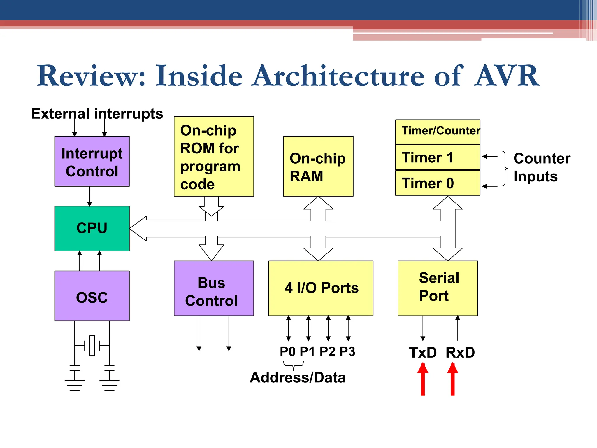
Review: Inside Architectureof AVR
CPU
On-chip
RAM
On-chip
ROM for
program
code
4 I/O Ports
Timer 0
Serial
Port
OSC
Interrupt
Control
External interrupts
Timer 1
Timer/Counter
Bus
Control
TxD RxD
P0 P1 P2 P3
Address/Data
Counter
Inputs
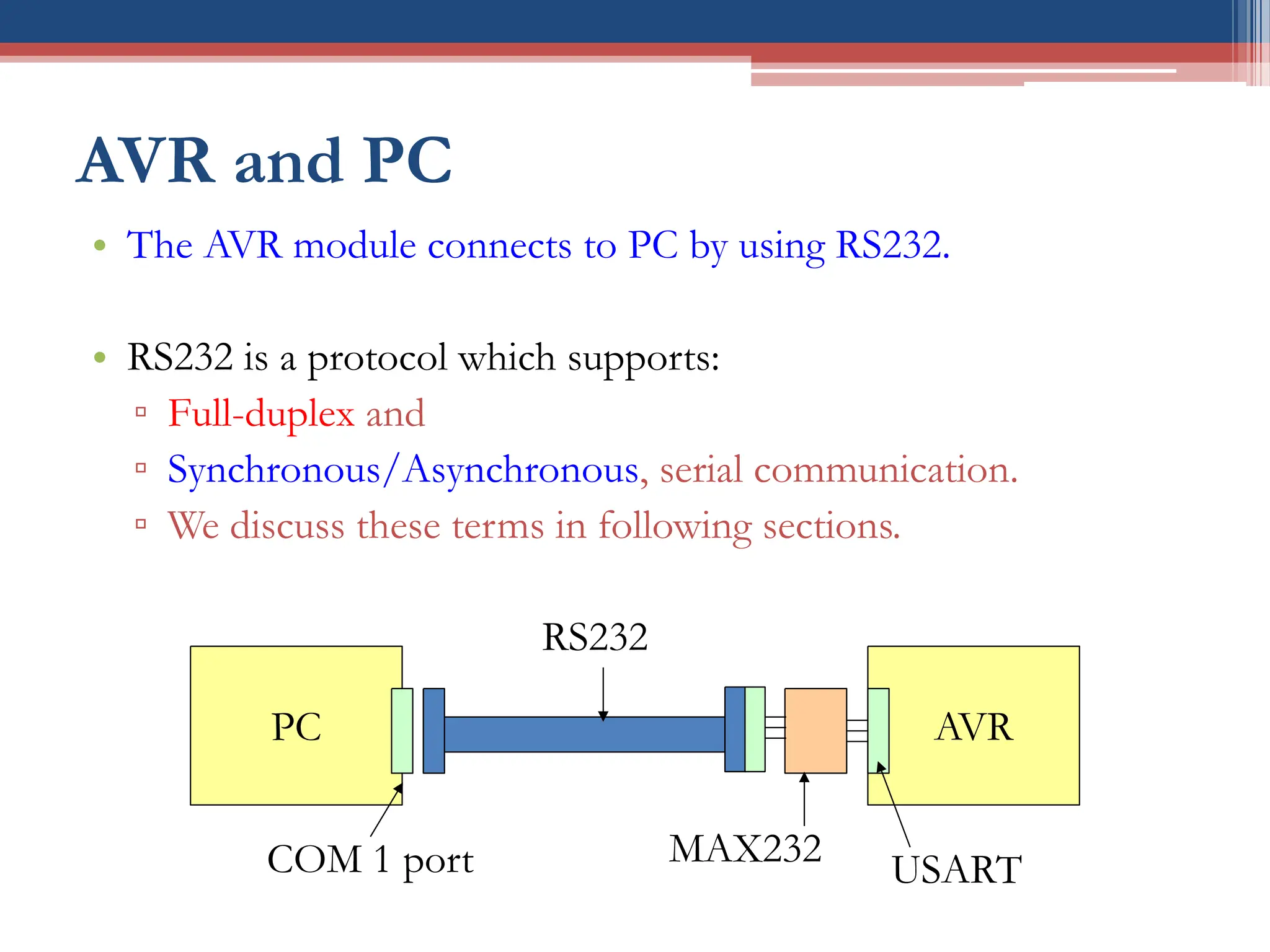
AVR and PC
•The AVR module connects to PC by using RS232.
• RS232 is a protocol which supports:
▫ Full-duplex and
▫ Synchronous/Asynchronous, serial communication.
▫ We discuss these terms in following sections.
PC AVR
COM 1 port
RS232
MAX232
USART
5.
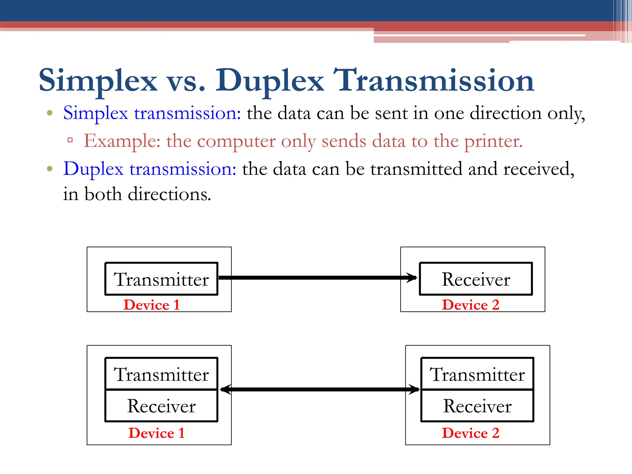
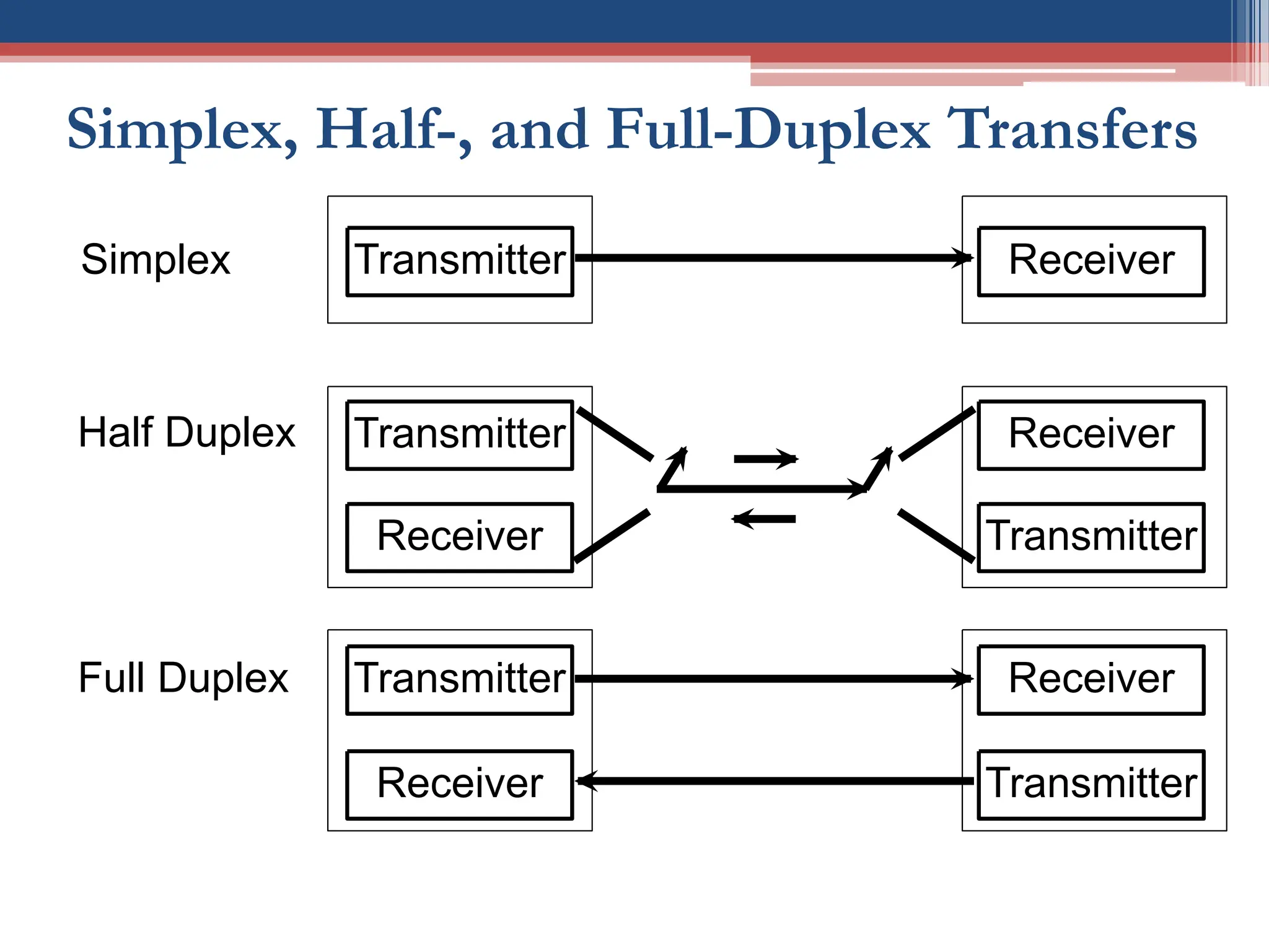
Simplex vs. DuplexTransmission
• Simplex transmission: the data can be sent in one direction only,
▫ Example: the computer only sends data to the printer.
• Duplex transmission: the data can be transmitted and received,
in both directions.
Transmitter Receiver
Transmitter
Receiver
Receiver
Transmitter
Device 1 Device 2
Device 2
Device 1
6.
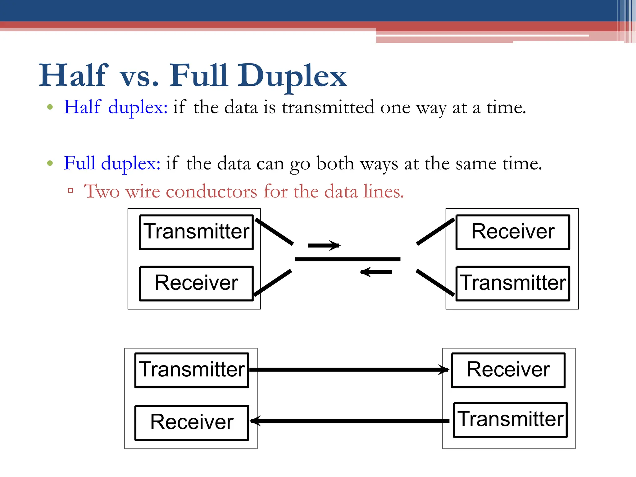
Half vs. FullDuplex
• Half duplex: if the data is transmitted one way at a time.
• Full duplex: if the data can go both ways at the same time.
▫ Two wire conductors for the data lines.
Transmitter
Receiver
Receiver
Transmitter
Transmitter
Receiver
Receiver
Transmitter
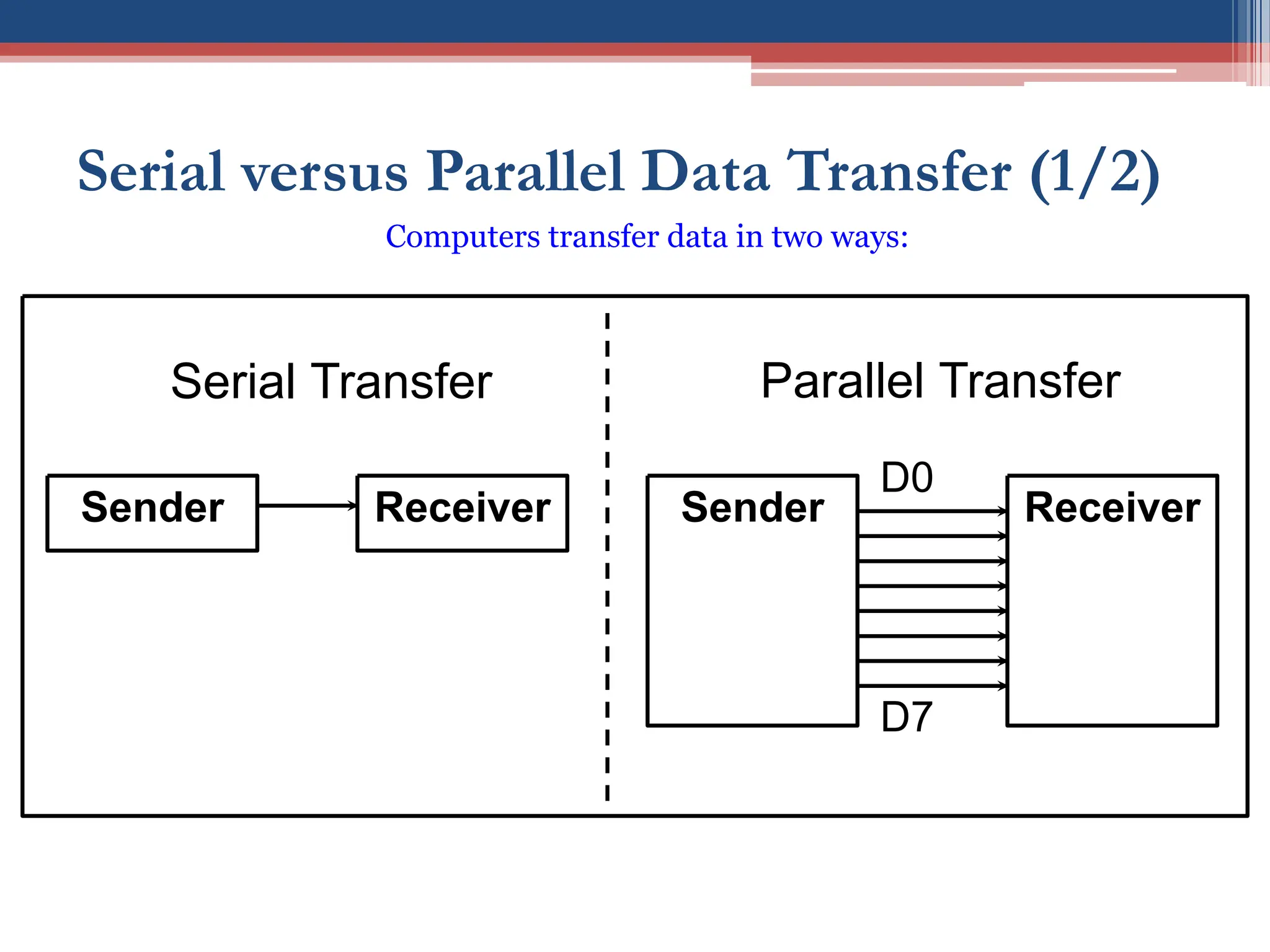
Serial versus ParallelData Transfer (1/2)
Sender Receiver Sender Receiver
Serial Transfer Parallel Transfer
D0
D7
Computers transfer data in two ways:
9.
Parallel vs. Serial
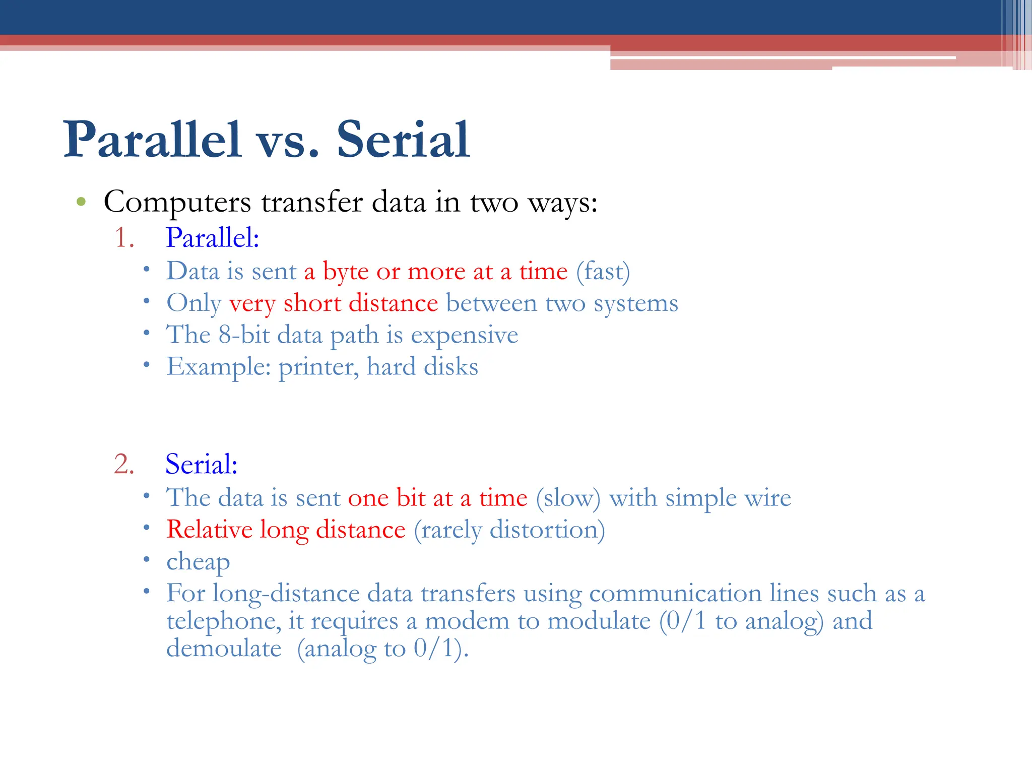
•Computers transfer data in two ways:
1. Parallel:
Data is sent a byte or more at a time (fast)
Only very short distance between two systems
The 8-bit data path is expensive
Example: printer, hard disks
2. Serial:
The data is sent one bit at a time (slow) with simple wire
Relative long distance (rarely distortion)
cheap
For long-distance data transfers using communication lines such as a
telephone, it requires a modem to modulate (0/1 to analog) and
demoulate (analog to 0/1).
10.
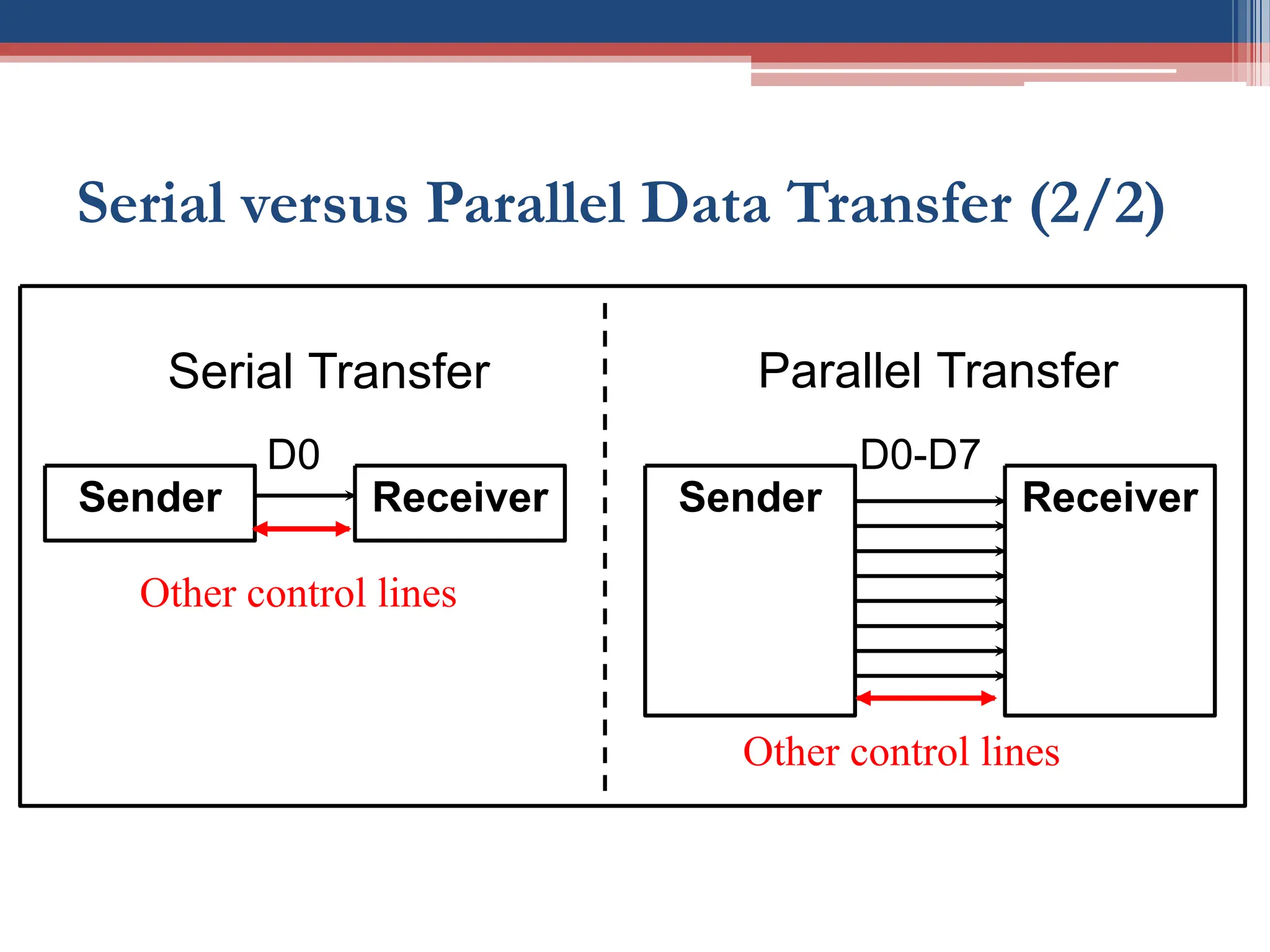
Serial versus ParallelData Transfer (2/2)
Sender Receiver Sender Receiver
Serial Transfer Parallel Transfer
D0-D7
D0
Other control lines
Other control lines
11.
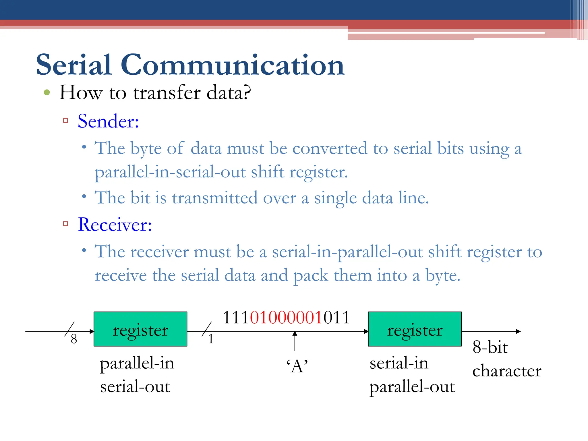
Serial Communication
• Howto transfer data?
▫ Sender:
The byte of data must be converted to serial bits using a
parallel-in-serial-out shift register.
The bit is transmitted over a single data line.
▫ Receiver:
The receiver must be a serial-in-parallel-out shift register to
receive the serial data and pack them into a byte.
11101000001011
‘A’
register
8-bit
character
register
8 1
parallel-in
serial-out
serial-in
parallel-out
12.
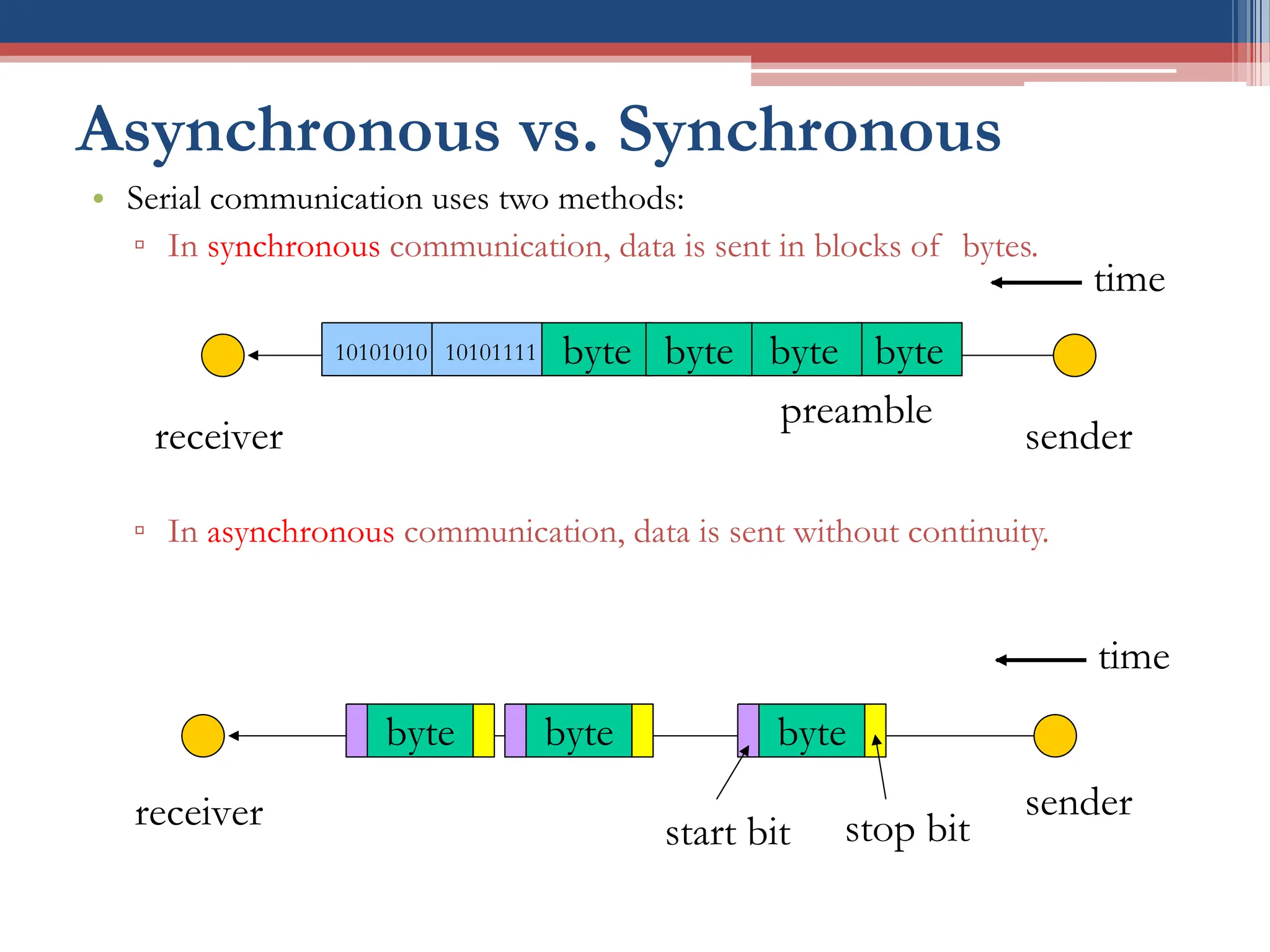
Asynchronous vs. Synchronous
•Serial communication uses two methods:
▫ In synchronous communication, data is sent in blocks of bytes.
▫ In asynchronous communication, data is sent without continuity.
byte
byte
10101111
preamble
10101010
sender
receiver
byte byte
time
byte
sender
receiver start bit stop bit
byte
byte
time
13.
UART & USART
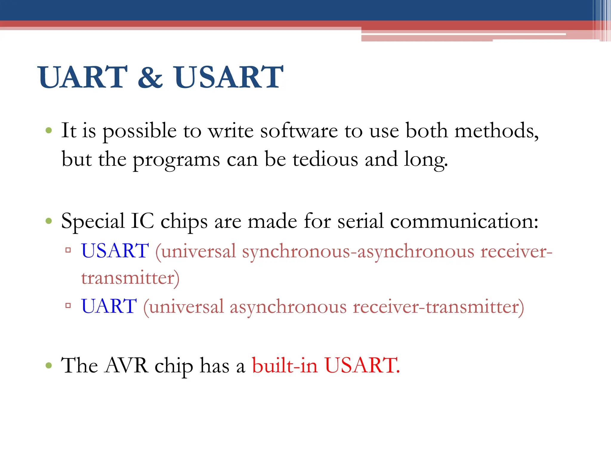
•It is possible to write software to use both methods,
but the programs can be tedious and long.
• Special IC chips are made for serial communication:
▫ USART (universal synchronous-asynchronous receiver-
transmitter)
▫ UART (universal asynchronous receiver-transmitter)
• The AVR chip has a built-in USART.
14.
AVR Serial Communication
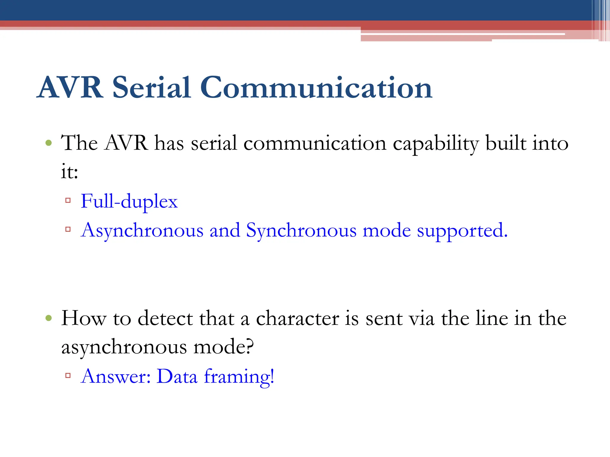
•The AVR has serial communication capability built into
it:
▫ Full-duplex
▫ Asynchronous and Synchronous mode supported.
• How to detect that a character is sent via the line in the
asynchronous mode?
▫ Answer: Data framing!
15.
Framing (1/3)
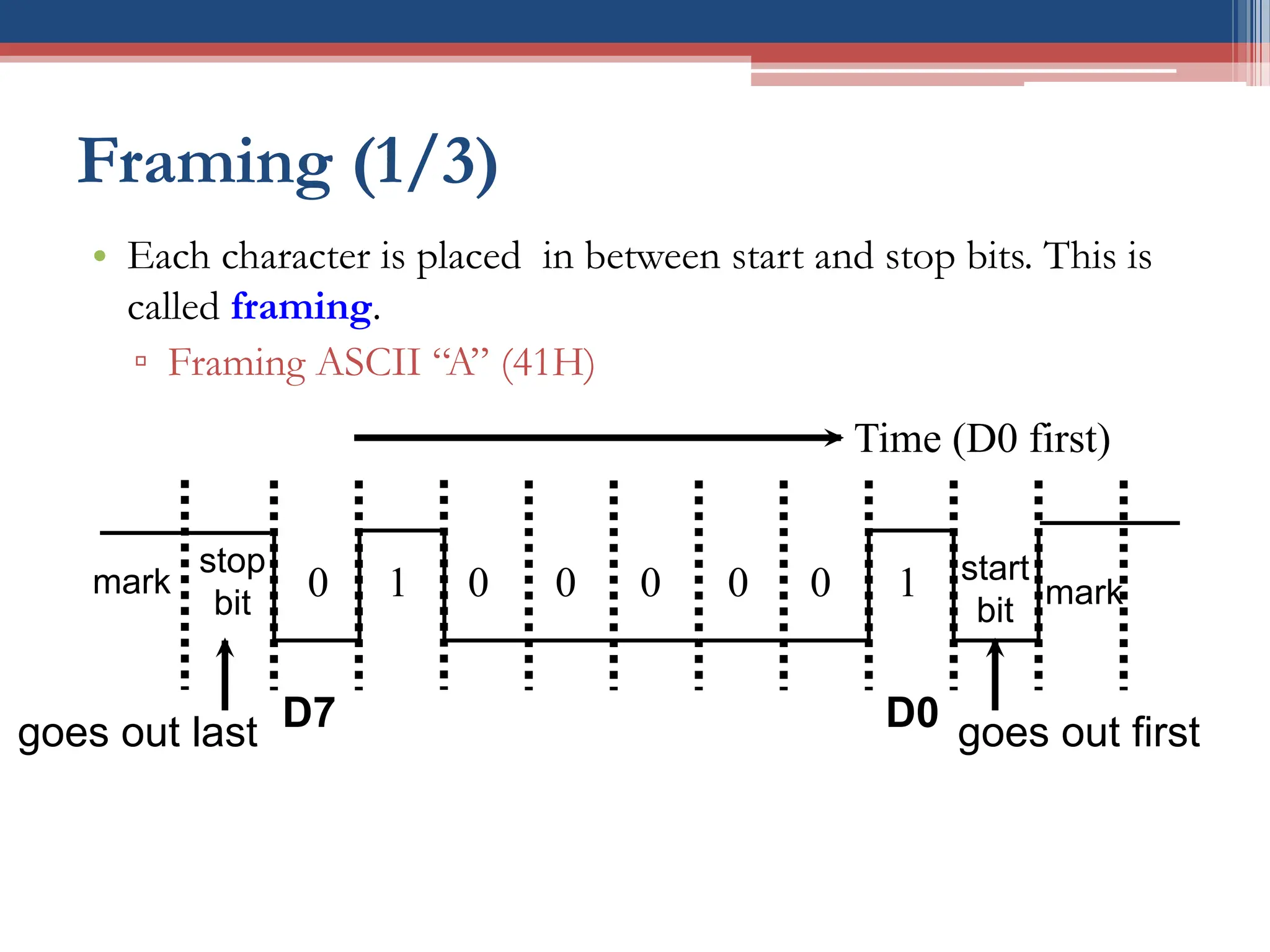
• Eachcharacter is placed in between start and stop bits. This is
called framing.
▫ Framing ASCII “A” (41H)
stop
bit
start
bit
mark
0 0 0 0 0 0
1 1
D7 D0
goes out last goes out first
Time (D0 first)
mark
16.
Framing (2/3)
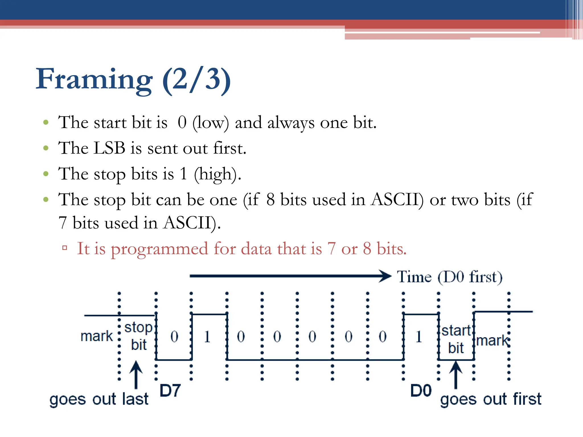
• Thestart bit is 0 (low) and always one bit.
• The LSB is sent out first.
• The stop bits is 1 (high).
• The stop bit can be one (if 8 bits used in ASCII) or two bits (if
7 bits used in ASCII).
▫ It is programmed for data that is 7 or 8 bits.
• When there is no transfer, the signal is 1 (high), which is
referred to as mark.
17.
Framing (3/3)
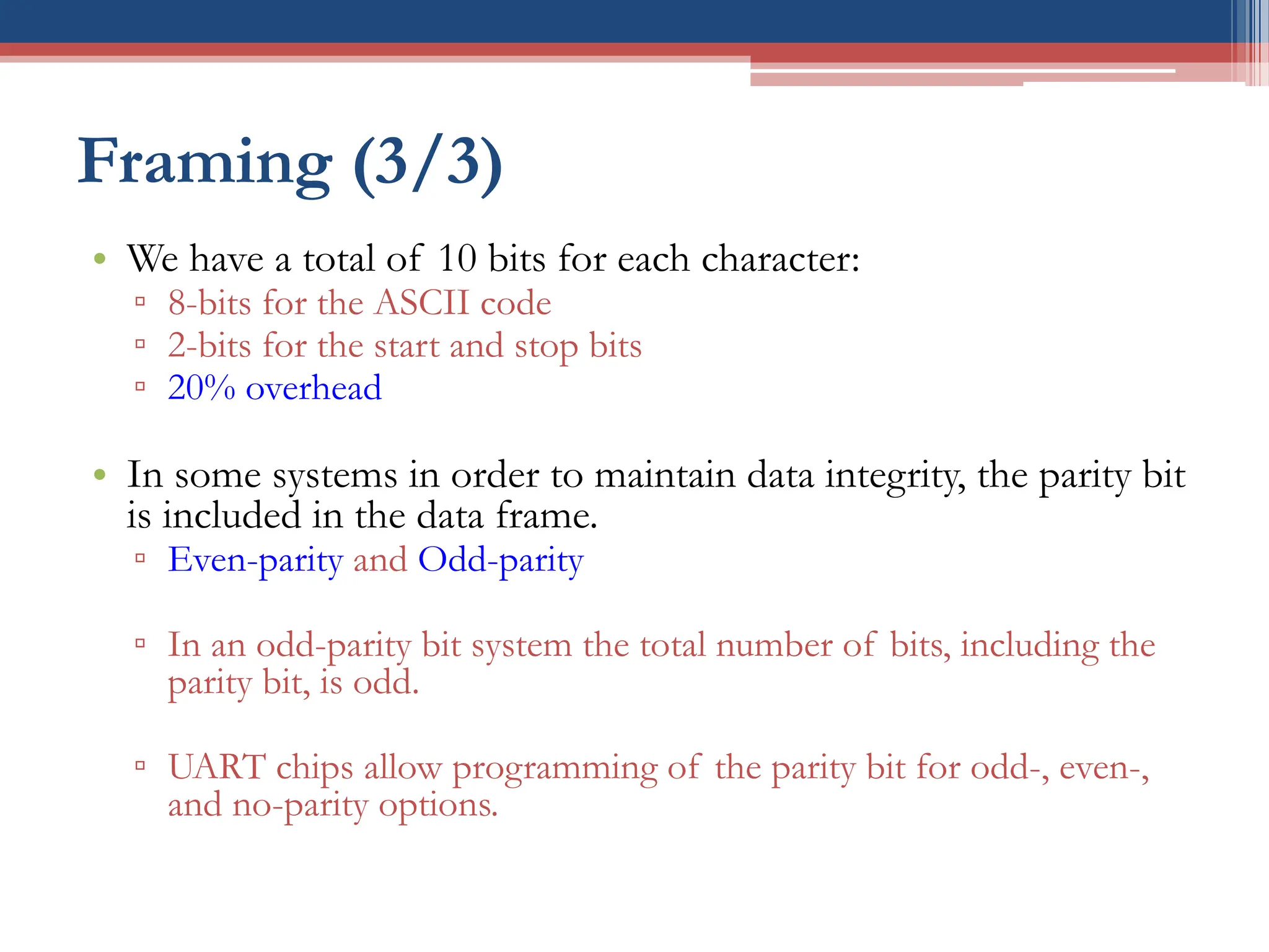
• Wehave a total of 10 bits for each character:
▫ 8-bits for the ASCII code
▫ 2-bits for the start and stop bits
▫ 20% overhead
• In some systems in order to maintain data integrity, the parity bit
is included in the data frame.
▫ Even-parity and Odd-parity
▫ In an odd-parity bit system the total number of bits, including the
parity bit, is odd.
▫ UART chips allow programming of the parity bit for odd-, even-,
and no-parity options.
18.
Data Transfer Rate
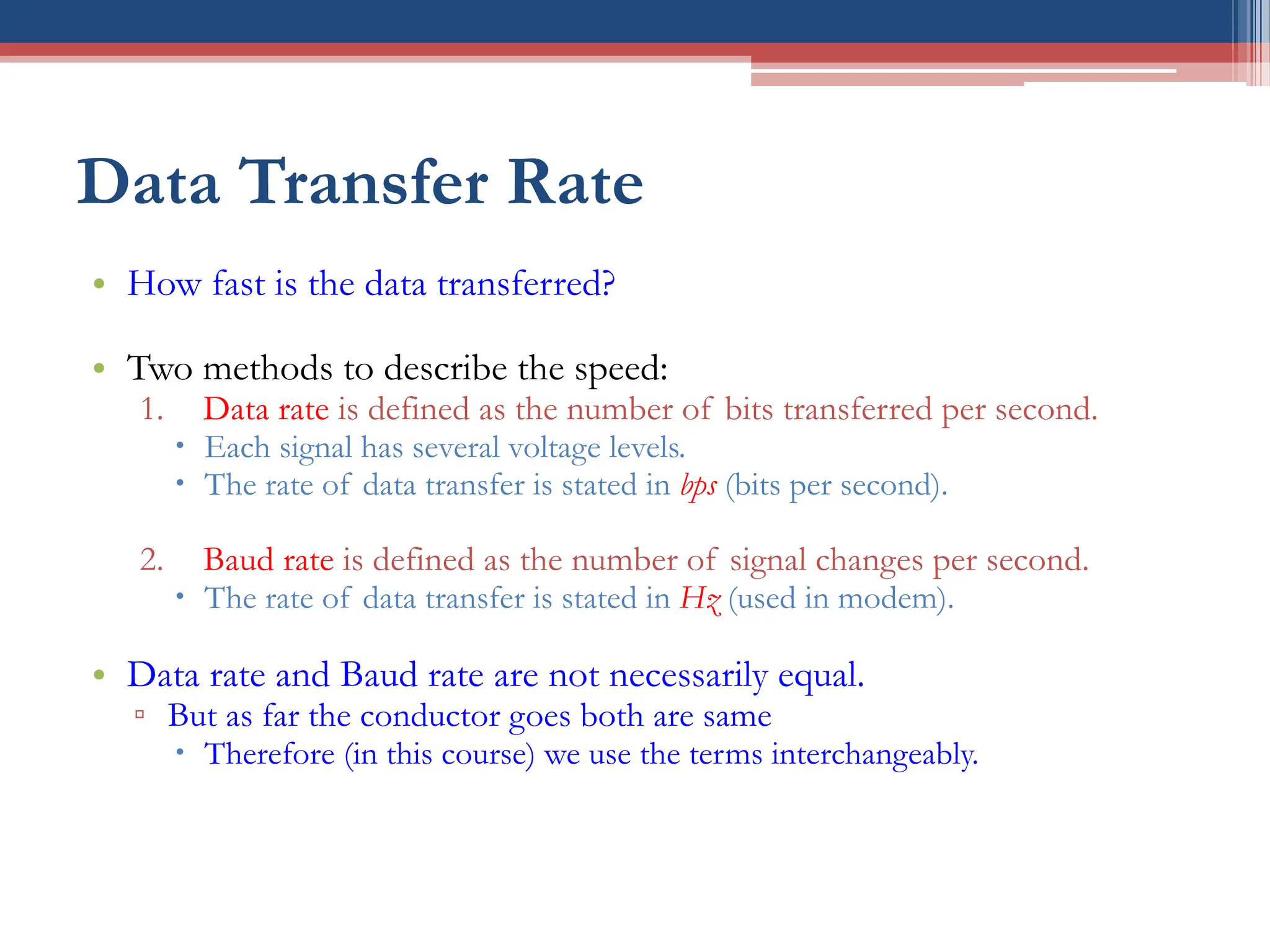
•How fast is the data transferred?
• Two methods to describe the speed:
1. Data rate is defined as the number of bits transferred per second.
Each signal has several voltage levels.
The rate of data transfer is stated in bps (bits per second).
2. Baud rate is defined as the number of signal changes per second.
The rate of data transfer is stated in Hz (used in modem).
• Data rate and Baud rate are not necessarily equal.
▫ But as far the conductor goes both are same
Therefore (in this course) we use the terms interchangeably.
19.
Example of DataTransfer Rate (1/2)
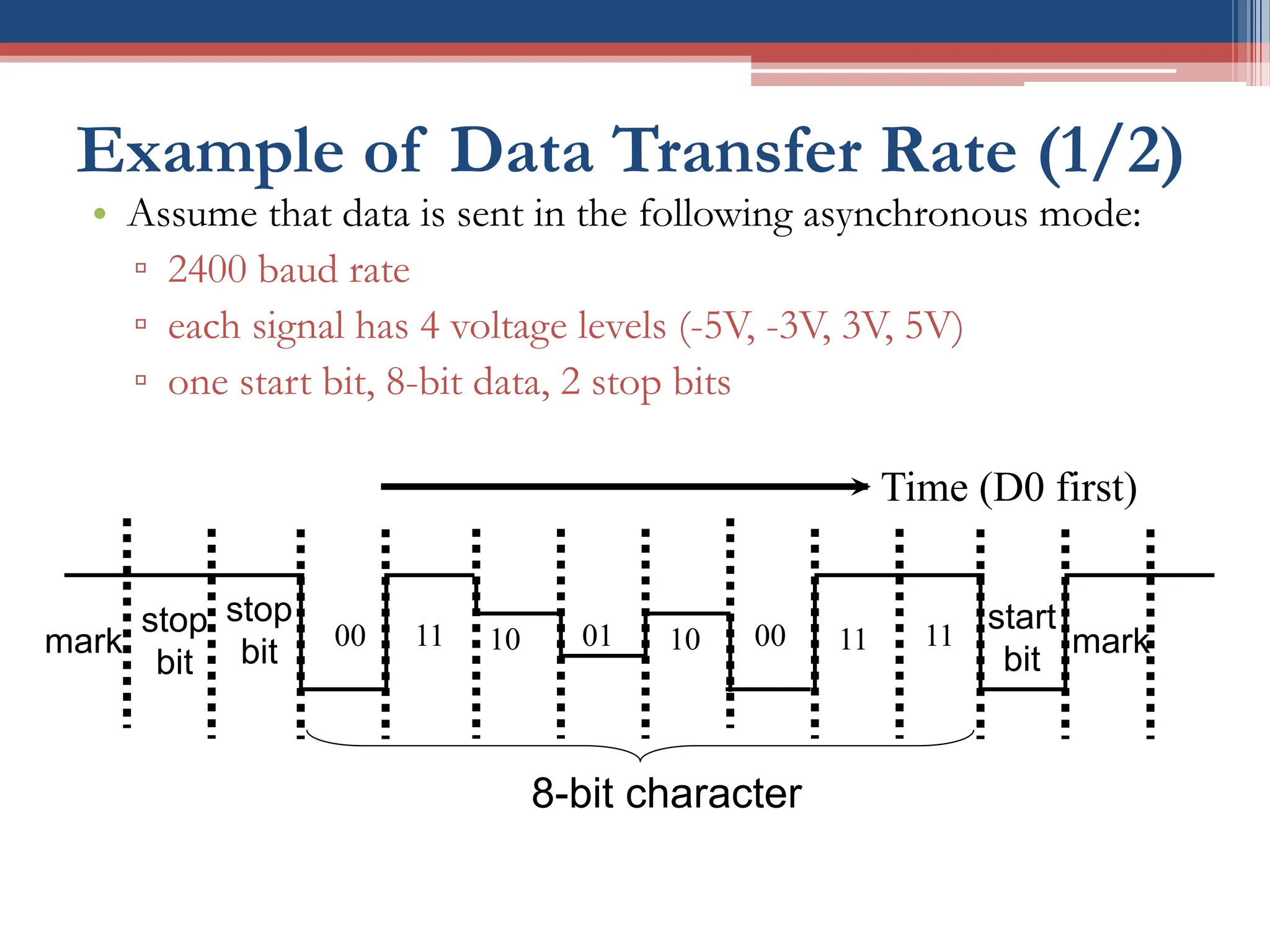
• Assume that data is sent in the following asynchronous mode:
▫ 2400 baud rate
▫ each signal has 4 voltage levels (-5V, -3V, 3V, 5V)
▫ one start bit, 8-bit data, 2 stop bits
mark
stop
bit
start
bit
mark
00 10 01 10 00 11
11 11
Time (D0 first)
8-bit character
stop
bit
20.
Example of DataTransfer Rate (2/2)
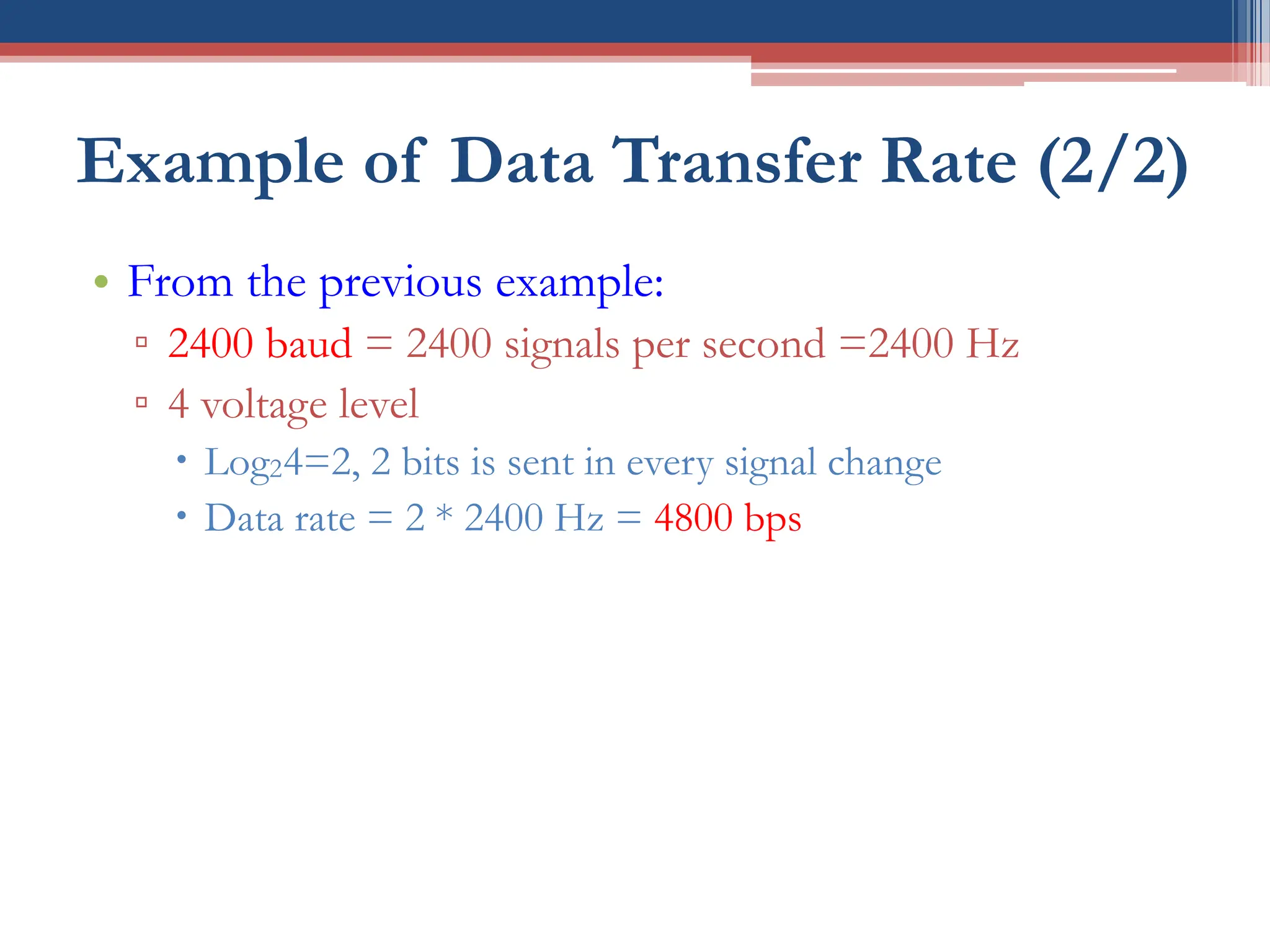
• From the previous example:
▫ 2400 baud = 2400 signals per second =2400 Hz
▫ 4 voltage level
Log24=2, 2 bits is sent in every signal change
Data rate = 2 * 2400 Hz = 4800 bps
21.
RS232 Standard
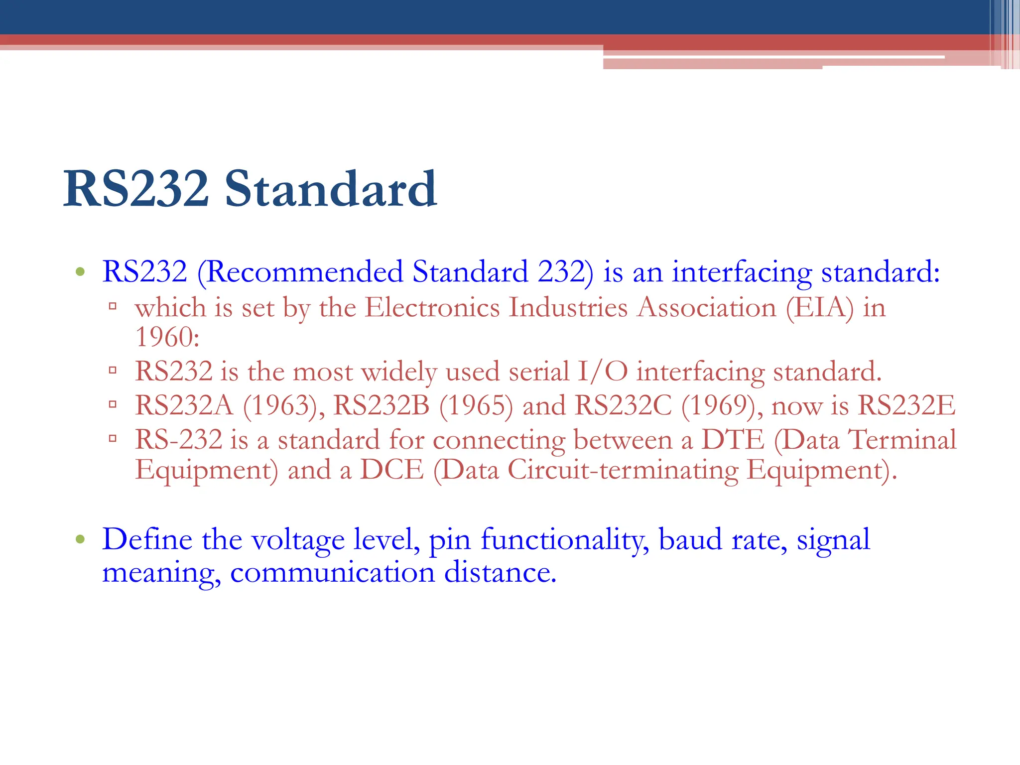
• RS232(Recommended Standard 232) is an interfacing standard:
▫ which is set by the Electronics Industries Association (EIA) in
1960:
▫ RS232 is the most widely used serial I/O interfacing standard.
▫ RS232A (1963), RS232B (1965) and RS232C (1969), now is RS232E
▫ RS-232 is a standard for connecting between a DTE (Data Terminal
Equipment) and a DCE (Data Circuit-terminating Equipment).
• Define the voltage level, pin functionality, baud rate, signal
meaning, communication distance.
22.
DTE and DCE
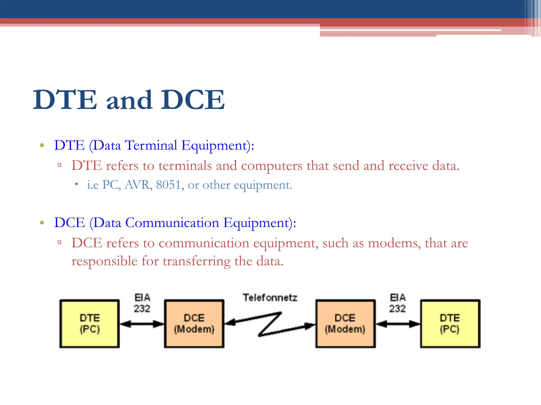
•DTE (Data Terminal Equipment):
▫ DTE refers to terminals and computers that send and receive data.
i.e PC, AVR, 8051, or other equipment.
• DCE (Data Communication Equipment):
▫ DCE refers to communication equipment, such as modems, that are
responsible for transferring the data.
23.
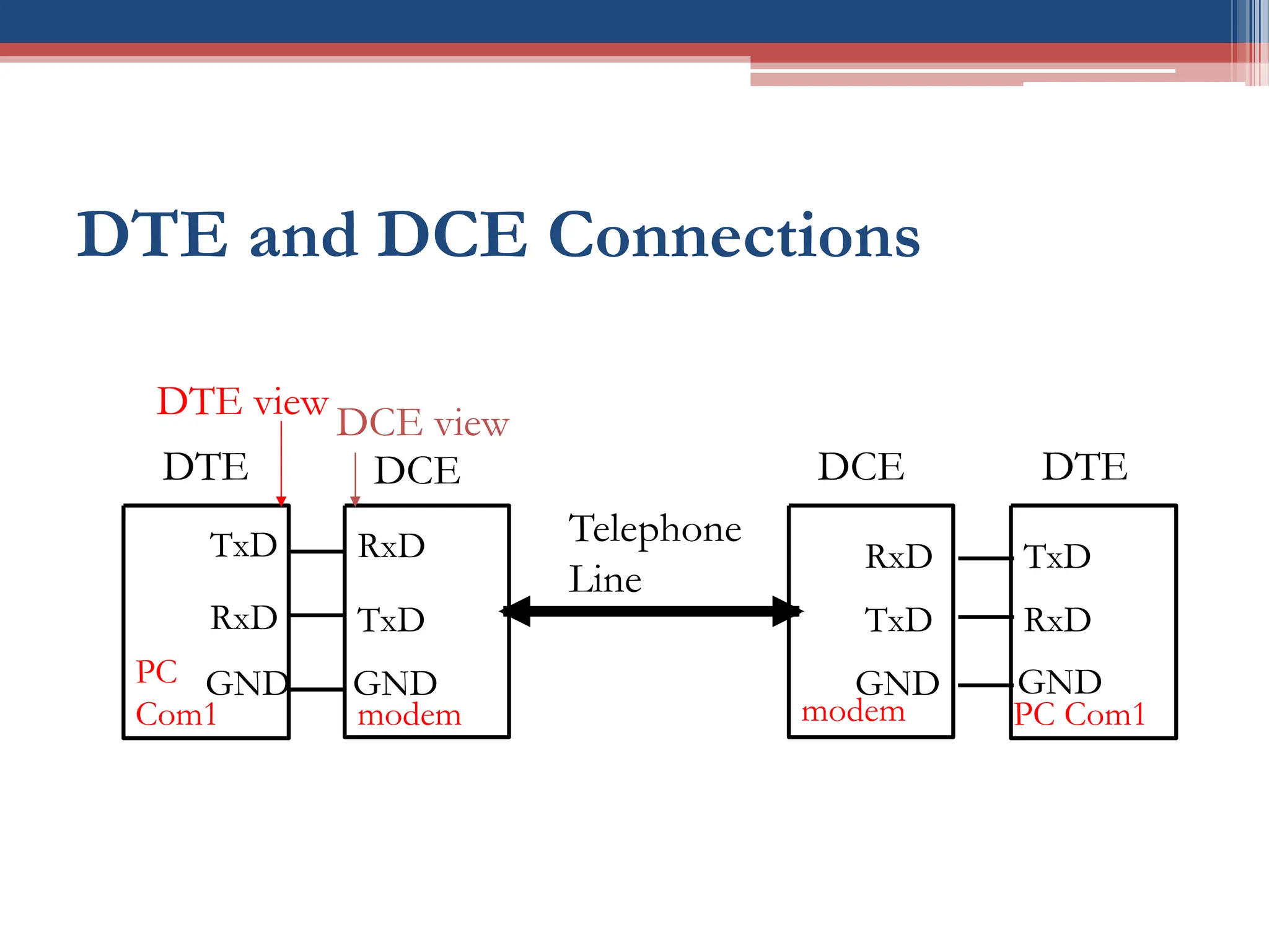
DTE and DCEConnections
TxD
RxD
DTE
RxD
TxD
DCE
GND
PC
Com1 modem
GND
TxD
RxD
DTE
RxD
TxD
DCE
GND
PC Com1
modem
GND
Telephone
Line
DTE view
DCE view
24.
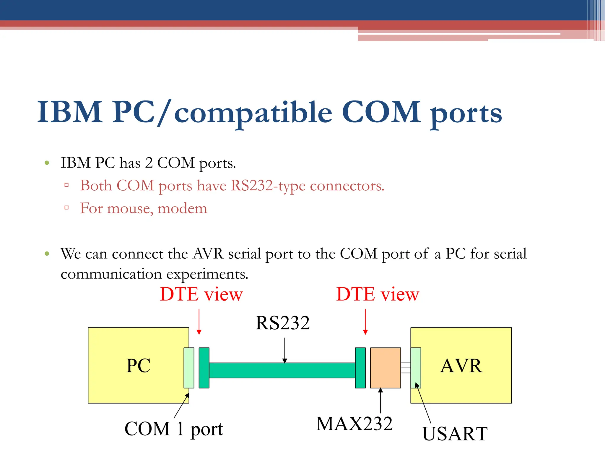
IBM PC/compatible COMports
• IBM PC has 2 COM ports.
▫ Both COM ports have RS232-type connectors.
▫ For mouse, modem
• We can connect the AVR serial port to the COM port of a PC for serial
communication experiments.
PC AVR
COM 1 port
RS232
MAX232
USART
DTE view DTE view
25.
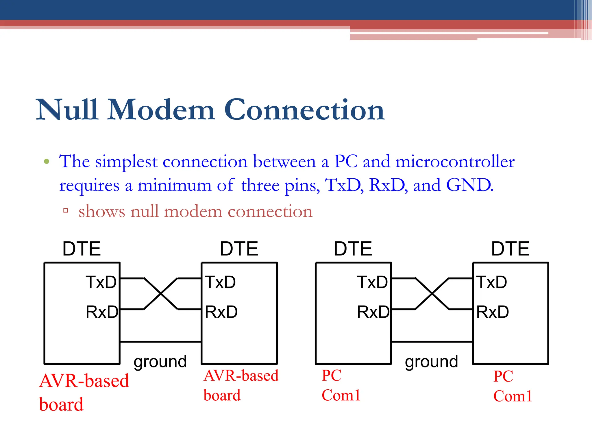
Null Modem Connection
•The simplest connection between a PC and microcontroller
requires a minimum of three pins, TxD, RxD, and GND.
▫ shows null modem connection
TxD
RxD
DTE
TxD
RxD
DTE
ground
AVR-based
board
AVR-based
board
TxD
RxD
DTE
TxD
RxD
DTE
ground
PC
Com1
PC
Com1
26.
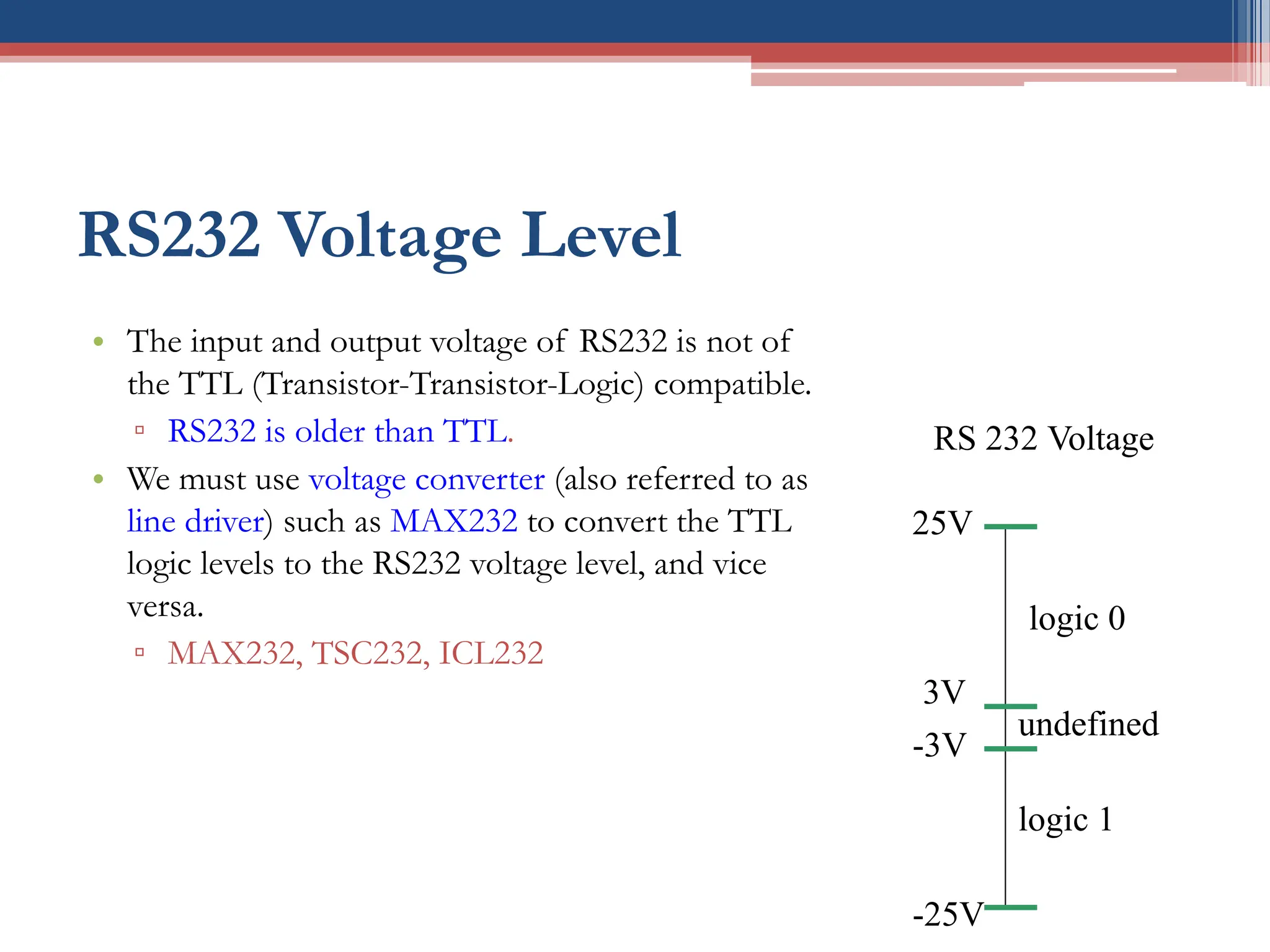
RS232 Voltage Level
•The input and output voltage of RS232 is not of
the TTL (Transistor-Transistor-Logic) compatible.
▫ RS232 is older than TTL.
• We must use voltage converter (also referred to as
line driver) such as MAX232 to convert the TTL
logic levels to the RS232 voltage level, and vice
versa.
▫ MAX232, TSC232, ICL232
logic 0
-3V
-25V
3V
25V
logic 1
undefined
RS 232 Voltage
27.
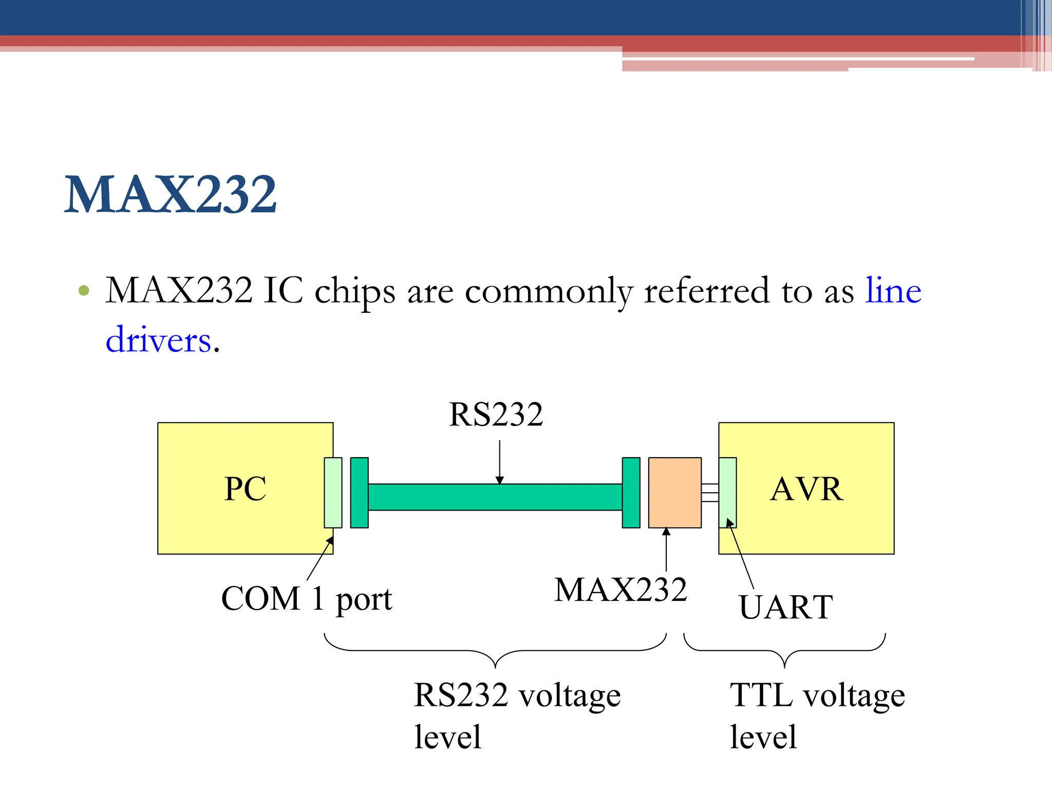
MAX232
• MAX232 ICchips are commonly referred to as line
drivers.
PC AVR
COM 1 port
RS232
MAX232
UART
RS232 voltage
level
TTL voltage
level
29
Conclusion
• Serial communicationbasics
▫ Simplex vs. duplex communication
▫ Synchronous & asynchronous communication
▫ Data rate & Baud rate.
▫ Connection between PC and AVR